10 minute read
Control and operation


Installation and removal of attachment parts
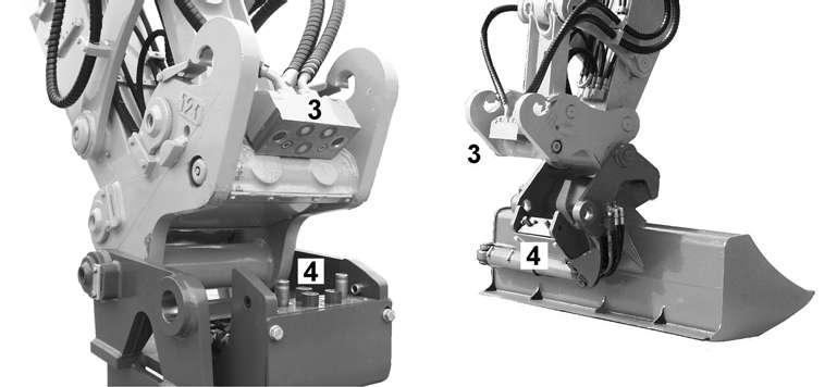
1 Protective cover on quick-change adapter
2 Protective covering on work tool
3 LIKUFIX hydraulic coupling on quick-change adapter
4 LIKUFIX hydraulic coupling on work tool
5 Alternative hydraulic coupling on work tool
Attaching and dismounting work tools
Attaching and dismounting is carried out as described in the chapter “Hydraulic quick-change adapter”.
Please also note:
Before attaching, remove the protective coverings on the quick-change adapter 1 and the work tool 2
Always keep hydraulic couplings 3 and 4 clean.
Perform a visual check for cleanliness before attaching. If necessary, clean all coupling parts and the sealing surfaces with a clean, oil-soaked cloth.
Connect or separate the hydraulic coupling slowly as with any change of work tool.
When attaching the quick-change adapter, tilt until the coupling disks are connected as a result of the self weight of the work tool. Remove the locking pins.
If the disks do not connect as a result of self weight, foreign matter (such as stones) may be the cause. In this case, clean all coupling parts to prevent damage occurring when connecting.
Oil quantity and pressure must be adapted to suit the work device concerned.
When the work is completed, and particularly before transportation, put the protective coverings 1 and 2 back on.
Attaching LIKUFIX work tools to a quick-change adapter without LIKUFIX
It is possible to attach a work tool with a LIKUFIX hydraulic coupling to a machine with a quick-change adapter (mechanical or hydraulic) at any time.
Caution!
The LIKUFIX hydraulic coupling could be damaged. Do not use a quick-change adapter with a reinforcement kit since the reinforced steel part 6 could damage the LIKUFIX hydraulic coupling on the work tool. In this case, ensure that you have the quick-change adapter reworked at the LIEBHERR customer service centre.
For attachment without LIKUFIX hydraulic coupling, LIEBHERR work tools usually have an alternative connection option.
Example:
On the ditcher bucket, hydraulic lines are either connected using LIKUFIX 4 or using an auxiliary hydraulic connection 5
3.8Working methods
3.8.1Minimum impact working methods for your machine
To increase the service life of the machine and avoid unnecessary damage and the resulting repairs, please note the following points:
–Do not stop the rotary motion of the upper carriage when slewing into a ditch by stopping the equipment on the walls of the ditch.
–Using the machine for applications where the equipment is knocked against the material to be removed, in the longitudinal direction too, is not permitted. Repeatedly hitting the work equipment against rock or other hard material will damage steel parts and machine components.
–With specific combinations of boom, stick and work tool, the work tool could hit or break through into the cab. This could damage the cab and injure the machine’s operator.
–Do not attach buckets which are too big or side cutters when using the machine in rocky material. This will extend the work cycles and could result in damage to the bucket and other machine components.
–Please contact your LIEBHERR contractual partner if special teeth are required for heavy or special applications.
–Operating the drag bearing to bore into material is not permitted.
–Do not raise the machine when working. If this should occur, slowly lower the machine to the ground.
–Do not permit the machine to lower quickly and do not intercept the falling movement using the hydraulics, since this could result in damage to the machine.
3.8.2Preparatory activities
Danger!
Risk of fatal injury and damage to the machine when working. Observe the safety information “Notes for safe working” at the start of these operating instructions.
3-123 Working position – machine
Position the machine so that the load or grab material can be taken up above the rigid axle or the leading wheel. For mobile devices, lower the support when possible and lock the full floating axle.
Danger!
Insufficient support and machine damage. Do not use a skimming shield to support the machine.
Working
Danger!
Risk of fatal injury due to rotating the machine. Ensure that nobody stands within the danger area r of the machine.
Caution!
Risk of injury when working.
Always wear safety shoes and, particularly when leaving the cab when demolition work is going on, a protective helmet and goggles. Always wear the seat belt.
Use the horn to give a short warning signal before starting work.
3.8.3Using a backhoe bucket
Danger!
Risk of fatal injury and damage to the machine when moving the backhoe bucket. Ensure that the backhoe bucket is not slewed too close to the cab. The backhoe bucket could damage the cab and injure the machine’s operator.
Ensure that nobody is standing within the danger area of the backhoe bucket.
The machine must be in the working position.
Align the stick in such a way that its underside is at an angle of approx. 45° to the ground.
Align the backhoe backhoebucket in such a way that its ground side can enter the ground at an angle of approx. 90°.
To lift out the grab material, slowly and evenly slew in the stick and slowly and evenly slew in the backhoe bucket simultaneously.
As soon as the stick is perpendicular to the ground, raise the boom slowly and evenly in addition to slewing in the stick and the backhoe bucket. Stopping suddenly will result in impact loads and vibrations.
When the backhoe bucket is full or the stick can no longer be slewed in, raise the boom and backhoe bucket until the filled surface is parallel to the ground.
3.8.4Loading a transport vehicle
Danger!
Risk of fatal injury due to falling grab material.
Do not load the transport vehicle so high that the grab material could drop out over the walls of the vehicle.
Ensure that nobody is standing in the danger area or in the transport vehicle when loading.
Do not slew the equipment over the driver’s cab.
Emptying grab material
If possible, the machine should stand higher than the transport vehicle to avoid having to lift the grab material unnecessarily.
Stop the transport vehicle in a position that allows it to be loaded from the rear or the side.
Slew the machine's equipment above the loading area of the transport vehicle. Distribute the grab material evenly over the loading area of the transport vehicle by slewing the backhoe bucket and the stick out, slewing the upper carriage and possibly also moving the boom.
If the backhoe bucket is not sufficiently emptied or there is still grab material in the backhoe bucket, slew the backhoe bucket in and out several times to loosen the grab material.
3.8.5Skimming
Skimming work can either be carried out using the bucket or with a skimming shield (optional extra).
The machine must be in the working position. The support should be raised.
Danger!
Serious risk of injury when moving the machine. Ensure that nobody is standing within the working area of the machine.
Caution!
The machine could be damaged. Never move the machine while the work equipment is touching the ground.
To skim with a backhoestick bucket, lay this on the ground (see Fig. 3-129) and move the stick slowly forwards and backwards. Move the boom steadily up and down while the stick is moving.
If a skimming shield is present (optional extra), lower it to the ground and move slowly forwards and backwards with the machine.
3.8.6Using a clamshell bucket (earthmoving attachment)
Danger!
Risk of fatal injury and damage to the machine due to a swinging clamshell. Ensure that the shell type bucket does not swing too close to the cab. The shell type bucket could damage the cab when swinging and injure the machine’s operator.
Ensure that the shell type bucket does not swing towards anyone in the working area.
The shell type bucket could injure people standing in the vicinity when swinging.
Move the joystick slowly and evenly to prevent the shell type bucket swinging. Hold the stick in such a way that the shell type bucket cannot swing towards the machine when driving or braking.
Do not lift a load with the boom and stick extended too far and do not slew a heavy load too far to the left or right. The stability of the machine could be affected.
The machine must be in the working position.
Fig. 3-130 Straightening the stick
Open the grab shells fully. Lower the stick perpendicular to the excavation area.
Fig. 3-131 Closing the grab shells
Close the grab shells. Raise the stick slightly when doing this in order to reduce ground pressure. Danger!
The device could lift out when closing the shell type bucket.
Close the grab shells fully. Raise the boom. Move the machine to the unloading area (eg. transport vehicle).
Slew the stick out as far as possible to prevent any risk due to the swinging grab. Open the grab shells, empty the grab material.
3.8.7Using a multiple tine grapple (industrial attachment)
The machine must be in the working position.
Fig.
Taking up the load
Take the load up above the supported corners of the machine to attain maximum stability.
The maximum lifting capacity is attained when the load is taken up as close to the chassis as possible.
Transporting a load
Transport the load close to the chassis, but with sufficient safety distance to the cab (swinging grab!) and as close to the ground as possible.
Caution!
Particularly when loading wood, it can be necessary when working with a grab to move with the working equipment raised and the load taken up. This will shift the centre of gravity of the machine upwards. The way the machine drives will be negatively affected because of this.
Please note the safety information “Use for loading work” at the beginning of these operating instructions.
3.8.8Using an hydraulic hammer
Please also refer to the operating instructions provided by the manufacturer of the hydraulic hammer.
Danger!
The hydraulic hammer must be selected very carefully. Operating requires increased care and attention.
Only use hydraulic hammers approved by LIEBHERR. The use of a hydraulic hammer not approved by LIEBHERR could damage steel parts or other machine components.
Only use the hydraulic hammer to break up rocks, concrete and other breakable objects.
To avoid damaging the machine, do not try to break up rocks or concrete by moving the lever on the work equipment or by the hydraulic hammer.
Do not use the drop power of the hydraulic hammer to break up rocks or other objects. Do not move objects with the hydraulic hammer. Do not lift the machine when using the hydraulic hammer. This could damage both the hydraulic hammer and the machine.
Do not use the hydraulic hammer to lift objects.
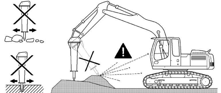
Only use the hydraulic hammer in the machine’s longitudinal direction.
Do not operate the hydraulic hammer in the direction of the machine, since exploding rocks or concrete could damage the machine and / or injure the driver. Close all windows in the cab before working.
Hydraulic hammer
The machine must be positioned in the working position on level, solid ground. The stick may not stand vertically.
No cylinder may be fully taken in or extended.
Do not operate the hydraulic hammer on the same spot continually or for longer than 15 seconds.
Overly continual operation of the hydraulic hammer leads to the hydraulic oil overheating unnecessarily.
Change the position of the machine and resume hammering work.
Danger!
The stability of the machine could be affected. When using a hydraulic hammer, only work with the machine in area A
3.8.9Working with a bottom dump bucket
Observe the following instructions in order to optimize the machine power as well the digging and breakout forces and the filling of the shovel and to help keeping the working place even and free of obstacles.
Filling the bottom dump shovel
Note!
Avoid digging with the attachment in a crosswise direction to the tracks.
3-138 Digging
If possible, start digging with the shovel at ground level and with the stick almost fully crowded back (50mm of cylinders stops).
When cleaning up the working place or digging, turn the teeth to an agressive angle so to break out more easy the obstacles that may be encountered in the material to be excavated.
Keep the bottom sheet of the shovel flap slightly raised up at the rear so ta avoid unnecessary friction forces between the soil and the bottom part of the shovel..
Caution!
Take care not to hit the shovel against the tracks each time you crowd back the stick to commence a new digging operation.
The flap must always be closed during digging operation. Take care not to reach the cylinder end positions or the mechanical stops of the shovel during the digging cycle. Continuously reaching the stops would lead to premature failure of seals and O-rings and can cause stress fractures to the flap, stick and shovel and damage to the boom and the uppercarriage.
Tilt the shovel down just before closing the flap. Doing so you allow the closing movement to be helped by the weight of the flap, while reducing at the same time the strike of the flap against the shovel back.
Never attempt to dig, level the working place, clean a cliff or bring down any material from an overhang, when the shovel flap is not fully closed. Such a practise can cause considerable damage to the flap cylinders.
Unloading the bottom dump shovel
Fig. 3-139 Unloading the shovel
Extend the stick and turn the uppercarriage at the same time, so to place the shovel over the carrier of the dump truck to be loaded.
Note!
The position of the shovel back when the flap opens, directly affects the falling down direction of the material.
Ideally, the load must fall straight down to the center of the dumper.
Open the flap (pos 1) and tilt simultaneously the shovel forward slightly, so the trajectory of the material is as vertical as possible.
When the shovel is empty, close the flap during the time the working attachment is returned to the ground level and to the position for starting a new digging sequence.
Modification of the undercarriage width (option)
3.9Modification of the undercarriage width (option)
3.9.1Mechanical modification of the undercarriage width
(Undercarriage types V, LCV or V-HDW)
General information
Park the machine on a level, firm and flat ground, such as on an asphalt or concrete base.
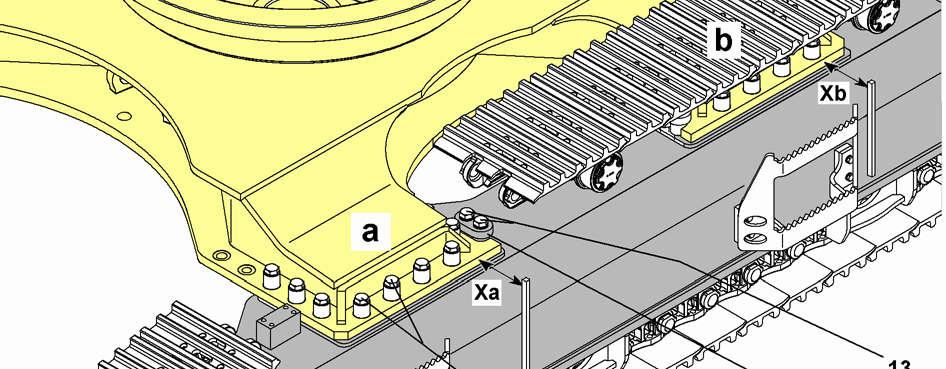
To change the track gauge, always move the both side frames inward or outward the one after the other. Before moving one of the side frames in or out, loosen and remove only the mounting screws 21 of the corresponding side frame.
Caution!
It is not permitted to move both side frames simultaneously!
Notice!
The retraction and the extension of the side frames are limited by the stops 11. It is not allowed to loosen the mounting bolts 13 (two per point a or b) of these stops during the width adjustment.
Before adjustment, remove the protective covers for the hydraulic hoses to the travel motors from the undercarriage central piece, if mounted.