Control and operation
Operating manual
Installation and removal of attachment parts
Operating elements
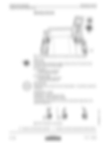
Fig. 3-112 Operating elements for the hydraulic quick-change adapter
Switch S19 Use switch S19 to activate the auxiliary hydraulic device for the grab torsional mechanism and quick-change adapter. Press switch. Auxiliary device is activated. LED in switch illuminates. Press switch again Auxiliary device is deactivated. LED in the switch goes out. Key switch S47: Pressing the button activates the quick-change adapter – it is possible to operate the locking pins.
Pushbuttons L and R Pushbutton L = extend locking pin (lock) Pushbutton R = retract locking pin (unlock) The pushbuttons are located on the left and/or right joystick (depending on the machine’s equipment):
Fig. 3-113 Pushbutton on the joystick E
Operation with left joystick (standard)
F
Operation with left and right joystick (optional extras)
copyright by
3 - 134
MJFCIFSS
R 974 C / 10069856


