Operating manual
Hydraulic excavator
R 313 Litronic
from serial number 57082
Document identification
ORIGINAL OPERATING MANUAL
Id. number: 11140221
Edition: 09 / 2013
Valid for: R 313 Litronic from serial number 57082
Author: LHB - Technical documentation department
Product identification
Manufacturer: LIEBHERR Hydraulikbagger GmbH
Type: R 313 Litronic
Type no.: 1038
Conformity: CE
Address
Liebherr Hydraulikbagger GmbH
Liebherr-Straße 12
D - 88457 Kirchdorf / Iller
en
Machine data
Please fill in the following data when you receive your machine. This will also be helpful when ordering spare parts.
Vehicle Id. No.:
WLHZ . . . . . . . . . . . .
Year of manufacture:
Delivery date: . . / . . / . .
Operating manual R 313 Litronic / 11140221 MJFCIFSS
This operating manual has been specifically devised for machine operators and maintenance personnel. It contains important warnings, information and tips regarding the maintenance and proper operation of the machine. It assists you in becoming familiar with the functions and features of the machine and helps prevent incorrect operation.
By strictly adhering to the instructions in the operating manual, you can significantly enhance the reliability and service life of the machine.
The operating manual is an integral part of the scope of delivery of the machine. Ensure that a copy is at all times available in the storage compartment in the operator's cab.
Carefully read the operating manual before starting the machine and then regularly read it again. All persons carrying out work on or with the machine must be fully familiar with the content of the operating manual and must adhere to the instructions.
Such work include:
– Machine operation including tooling, troubleshooting during work, general care and cleaning, disposal of fuels and lubricants.
– Maintenance including inspection, servicing and repair.
– Transport or loading of the machine.
The machine owner must ensure that this operating manual is complemented with the relevant statutory regulations for accident prevention and the protection of the environment. Apart from the instructions in this operating manual and the statutory accident prevention, health and safety regulations applicable in the country of operation, all personnel working on or with the machine must adhere to best practice for safe and proper operation.
Certain sections in this manual might not apply to your specific model.
Some of the figures in this operating manual might show details or equipment that differ from those in your machine.
Some of the figures show the equipment with guards or covers removed (for better depiction).
As our products are constantly being improved, certain changes might be made to the equipment which are not referred to specifically in this operating manual. Should you require additional information or if you have any queries, please contact the LIEBHERR customer service department.
Warranty and liability
Due to the range of products (e.g. fuels, lubricants, tool attachments, spare parts) available from other manufacturers, LIEBHERR is not in a position to assess the compatibility of these products with its own machines. This also applies in relation to possible effects that third-party products have on LIEBHERR products and vice versa.
1 - 1 R 313 Litronic / 11140221 MJFCIFSS copyright by Introduction
It is therefore the responsibility of the machine owner to assess whether third-party products can be safely used in conjunction with the LIEBHERR machine. LIEBHERR shall not be liable for damage to or downtimes of LIEBHERR machine caused by the use a third-party products. Such damage is not covered by the LIEBHERR warranty. LIEBHERR shall not be liable for damage caused by improper operation, insufficient maintenance or non-compliance with safety instructions.
Amendments, general terms and conditions, copyright
We reserve the right to modify our products and amend the instructions in this operating manual without prior notice.
The reproduction or publication of the content of this operating manual (including figures) is prohibited. LIEBHERR reserves all rights in this operating manual, including copyright.
The warranty and liability clauses of the general business terms and conditions of LIEBHERR apply.
1 - 2 Operating manual R 313 Litronic / 11140221 MJFCIFSS copyright by
Operating manual R 313 Litronic / 11140221 MJFCIFSS copyright by Table
1Product description.......................................................................................................................................1-1 1.1Design and overview.............................................................................................................................1-1 1.1.1Machine with earth-moving attachment....................................................................................1-1 1.1.2Uppercarriage...........................................................................................................................1-2 1.1.3Undercarriage...........................................................................................................................1-3 1.2Vibration emissions.................................... .......................1-3 1.3Sound emission.....................................................................................................................................1-4 1.4EC Declaration of Conformity................................................................................................................1-5 1.5Technical data.......................................................................................................................................1-6 2Safety notes, signs........................................................................................................................................2-1 2.1Symbols used in this operating manual.................................................................................................2-1 2.2Proper use.............................................................................................................................................2-2 2.3Safety instructions.................................................................................................................................2-2 2.3.1General safety instructions.......................................................................................................2-2 2.3.2Crushing and burn prevention..................................................................................................2-3 2.3.3Fire and explosion prevention................... .....2-4 2.4Signs on the machine............................................................................................................................2-4 2.4.1Introduction...............................................................................................................................2-4 2.4.2Safety and information signs....................................................................................................2-5 2.4.3ID tag......................................................................................................................................2-10 3Control, operation..........................................................................................................................................3-1 3.1Operating and control elements.............................................................................................................3-1 3.1.1Overview of operator's platform................................................................................................3-1 3.1.2Indicating elements..................................................................................................................3-2 3.1.3Control consoles.......................................................................................................................3-3 3.1.4Control unit...............................................................................................................................3-7 3.1.5Display and operator's menu..................................................................................................3-10 3.2Control.................................................................................................................................................3-21 3.2.1Entering and exiting the operator's cab..................................................................................3-21 3.2.2Safety lever............................................................................................................................3-23 3.2.3Operator seat.........................................................................................................................3-23 3.2.4Operator seat.........................................................................................................................3-31 3.2.5Windscreen............................................................................................................................3-35 3.2.6Sun blind................................................................................................................................3-36 3.2.7Emergency exit through rear window.....................................................................................3-36 3.2.8Inside lighting.........................................................................................................................3-37 3.2.9Fire extinguisher (optional equipment)*..................................................................................3-37 3.2.10Windshield wiper....................................................................................................................3-38 3.2.11Lighting...................................................................................................................................3-39 3.2.12Heating system.......................................................................................................................3-40 3.2.13A/c system (optional equipment)............................................................................................3-42 3.3Operation.............................................................................................................................................3-43 3.3.1Safety instructions..................................................................................................................3-43 3.3.2To see and to be seen............................................................................................................3-44 3.3.3Camera system (optional equipment)....................................................................................3-45 3.3.4Starting machine....................................................................................................................3-46 3.3.5Adjusting engine speed..........................................................................................................3-50 3.3.6Switching off the diesel engine...............................................................................................3-52 3.3.7Starting aid (Optional extra)...................................................................................................3-52 3.3.8Jump start procedure.............................................................................................................3-52 3.3.9Travel operation.....................................................................................................................3-53 3.3.10Travel alarm system (optional equipment).............................................................................3-56
of contents
Operating manual R 313 Litronic / 11140221 MJFCIFSS copyright by 3.3.11Blade support (optional equipment)........................................................................................3-56 3.4Working with the machine....................................................................................................................3-57 3.4.1Safety Instructions..................................................................................................................3-57 3.4.2Low idle automatic..................................................................................................................3-61 3.4.3Swivelling uppercarriage........................................................................................................3-61 3.4.4Halting uppercarriage.............................................................................................................3-62 3.4.5Working position.....................................................................................................................3-63 3.4.6Operating the working attachment.......................................................................................... 3-64 3.4.7Moving the boom....................................................................................................................3-65 3.4.8Lowering the working attachment when diesel engine is shut off...........................................3-66 3.4.9Horizontal boom movement (optional equipment)..................................................................3-66 3.4.10Swivelling uppercarriage.. .......3-68 3.4.11Halting uppercarriage.............................................................................................................3-69 3.4.12Adjustment of tool attachment................................................................................................3-70 3.4.13Operation of attachment (optional equipment).......................................................................3-70 3.4.14Changeover of the control system (optional equipment)........................................................3-72 3.4.15Operating attachment tool (mini joystick control, optional equipment)...................................3-73 3.4.16Changeover of joystick control (optional equipment)..............................................................3-75 3.4.17Super Finish (optional equipment)..........................................................................................3-75 3.4.18Attachments in continuous operation (optional equipment)....................................................3-76 3.4.19Stick cylinder shut-down function (optional equipment)..........................................................3-77 3.5Installation and removal of attachment parts.......................................................................................3-80 3.5.1Safety Instructions..................................................................................................................3-80 3.5.2Installation and removal of digging tool.................................................................................. 3-81 3.5.3Attachment of grapple to bucket stick..................................................................................... 3-83 3.5.4Mechanical quick-change adapter (optional equipment)........................................................3-86 3.5.5Hydraulic quick-change adapter (optional equipment)...........................................................3-90 3.5.6Hydraulic quick-change adapter with LIKUFIX (optional equipment).....................................3-95 3.6General working methods....................................................................................................................3-96 3.6.1Tips for the proper operation of the machine preventing damage and wear..........................3-96 3.6.2Preparation.............................................................................................................................3-98 3.6.3Working with the backhoe bucket.................. 3-98 3.6.4Loading transport vehicle.....................................................................................................3-100 3.6.5Grading work........................................................................................................................3-101 3.6.6Working with grapples..........................................................................................................3-102 3.6.7Excavating and moving material with grapples.....................................................................3-102 3.6.8Working with the hydraulic hammer......................................................................................3-103 3.6.9Load lifting operation............................................................................................................3-105 3.6.10Use of quick-change adapter for load lifting operation.........................................................3-105 3.6.11Overload warning system (optional equipment)...................................................................3-106 3.7Parking and exiting machine..............................................................................................................3-107 3.8Transport............................................................................................................................................3-108 3.8.1Safety instructions................................................................................................................3-108 3.8.2Transportation on low-loader................................................................................................3-108 3.8.3Loading with crane...............................................................................................................3-110 4Malfunctions...................................................................................................................................................4-1 4.1Error code list.........................................................................................................................................4-1 4.2Troubleshooting.....................................................................................................................................4-6 4.2.1Diesel engine and fuel system..................................................................................................4-6 4.2.2Hydraulic system......................................................................................................................4-7 4.2.3Travel gearbox..........................................................................................................................4-8 4.2.4Electrical system.......................................................................................................................4-8 4.2.5Heating and air-conditioning system......... .4-9 4.2.6Working attachment..................................................................................................................4-9 4.3Fuses and relays..................................................................................................................................4-10 4.3.1Fuse box E50.........................................................................................................................4-10 4.3.2Control console C...................................................................................................................4-11
Operating manual R 313 Litronic / 11140221 MJFCIFSS copyright by 4.3.3Control console......................................................................................................................4-12 4.3.4Battery box.............................................................................................................................4-13 4.4Emergency mode.................................................................................................................................4-13 4.4.1Purpose..................................................................................................................................4-13 4.4.2Towing the machine...............................................................................................................4-14 5Maintenance...................................................................................................................................................5-1 5.1Safety instructions.................................................................................................................................5-1 5.1.1General safety instructions.......................................................................................................5-1 5.1.2Checking for cracks..................................................................................................................5-1 5.1.3Welding....................................................................................................................................5-2 5.1.4Fuels, lubricants and process chemicals..................................................................................5-2 5.1.5Repair.......................................................................................................................................5-2 5.1.6Electrical system......................................................................................................................5-3 5.1.7Pressure accumulator..............................................................................................................5-3 5.1.8Hydraulic hoses and lines........................................................................................................5-4 5.1.9Cab protection (FOPS).............................................................................................................5-5 5.2Access doors for maintenance..............................................................................................................5-5 5.2.1Overview of access doors........................................................................................................5-5 5.2.2Door lock..................................................................................................................................5-6 5.2.3Bonnet release mechanism......................................................................................................5-7 5.3Cleaning machine..................................................................................................................................5-7 5.4Care for rubber components..................................................................................................................5-8 5.5Fuels, lubricants and process chemicals...............................................................................................5-8 5.5.1General information..................................................................................................................5-8 5.5.2Lubricating chart.....................................................................................................................5-10 5.5.3Lubricant table........................................................................................................................5-11 5.5.4Fuels, lubricants and process chemicals................................................................................5-12 5.6Specifications for fuels, lubricants and process chemicals.................................................................. 5-12 5.6.1Fuels and lubricant for the diesel engine................................................................................5-12 5.6.2Hydraulic oil............................................................................................................................5-12 5.6.3Lubricants for axles and gearboxes.......................................................................................5-18 5.6.4Lubricating oil for transmission...............................................................................................5-19 5.6.5Grease....................................................................................................................................5-20 5.6.6Lubricants and care products for electrical and mechanical components..............................5-20 5.6.7Grease and other process chemicals.....................................................................................5-21 5.7Diesel engine.......................................................................................................................................5-21 5.7.1Check oil level........................................................................................................................5-21 5.7.2Changing the oil.....................................................................................................................5-22 5.8Cooling system....................................................................................................................................5-22 5.8.1Checking and cleaning the cooling system............................................................................5-22 5.8.2Checking coolant level...........................................................................................................5-23 5.8.3Corrosion inhibitor and antifreeze agent................................................................................5-24 5.8.4Changing coolant...................................................................................................................5-24 5.9Fuel system.........................................................................................................................................5-25 5.9.1Refuelling...............................................................................................................................5-26 5.9.2Draining the water from the fuel tank..................................................................................... 5-27 5.9.3Emptying and cleaning the fuel tank......................................................................................5-27 5.9.4Fuel pre-filter..........................................................................................................................5-28 5.9.5Replacement of fuel filter cartridge (fine filter)........................................................................ 5-29 5.10Dry air filter..........................................................................................................................................5-30 5.10.1Cleaning the dust removal valve............... ..5-30 5.10.2Replacing filter elements........................................................................................................5-30 5.10.3Checking the clean air line.....................................................................................................5-32 5.11Hydraulic system.................................................................................................................................5-32 5.11.1Checking the oil level in the hydraulic tank............................................................................5-33 5.11.2Releasing the pressure from the hydraulic system.................................................................5-34 5.11.3Releasing tank pressure.........................................................................................................5-34
Operating manual R 313 Litronic / 11140221 MJFCIFSS copyright by 5.11.4Emptying and refilling hydraulic tank......................................................................................5-35 5.11.5Changing return filter..............................................................................................................5-36 5.11.6Changing control oil filter..................... ..........5-38 5.11.7Checking the control circuit....................................................................................................5-39 5.11.8Bleeding hydraulic pump........................................................................................................5-39 5.11.9Maintenance of hydraulic cylinders........................................................................................5-40 5.11.10Replacing hydraulic hoses......................................................................................................5-40 5.12Changing the oil on components.........................................................................................................5-41 5.12.1General notes.........................................................................................................................5-41 5.12.2Swin gear - oil change............................................................................................................5-42 5.12.3Travel gear - oil change..........................................................................................................5-43 5.13Drive.....................................................................................................................................................5-43 5.13.1Cleaning drive.........................................................................................................................5-43 5.13.2Checking fixtures of drive components...................................................................................5-44 5.13.3Checking chain tension..........................................................................................................5-45 5.13.4Tensioning chain....................................................................................................................5-45 5.13.5Releasing chain......................................................................................................................5-46 5.13.6Changing lubrication nipple....................................................................................................5-47 5.14Electrical system..................................................................................................................................5-47 5.14.1Notes regarding the electrical system....... 5-47 5.14.2Battery main switch................................................................................................................5-48 5.14.3Battery care............................................................................................................................5-49 5.14.4Slip ring body (optional equipment)........................................................................................5-50 5.15Heating system....................................................................................................................................5-51 5.15.1Ambient air filter......................................................................................................................5-51 5.15.2Heating system.......................................................................................................................5-52 5.15.3Air-conditioning system (optional equipment).........................................................................5-53 5.16Automatic lubrication of the machine...................................................................................................5-53 5.16.1Fully automatic central lubrication system (optional equipment)............................................5-53 5.17Manual lubrication of the machine.......................................................................................................5-55 5.17.1Central slewing gear lube point..............................................................................................5-55 5.17.2Lubricating the attachment.....................................................................................................5-56 5.17.3Digging buckets / bucket tilting device....................................................................................5-56 5.17.4Attachments (optional equipment)..........................................................................................5-57 5.17.5Hydraulic quick change adapter.............................................................................................5-57 5.17.6Mechanical quick-change adapter.......................................................................................... 5-58 5.18Couplings of the quick-change adapter systems (optional equipment) ...............................................5-59 5.18.1Hydraulic coupling..................................................................................................................5-59 5.18.2LIKUFIX electric coupling.......................................................................................................5-60 5.19Travel and swing brakes......................................................................................................................5-61 5.20General maintenance tasks.................................................................................................................5-61 5.20.1Replacing wear parts.... .........5-61 5.20.2Replacing teeth on digging tool..............................................................................................5-61 5.20.3Welded parts on the machine.................................................................................................5-63 5.21Maintenance and inspection schedule.................................................................................................5-64
1Product description
1.1Design and overview
This section contains an overview of the machine and the displayed component parts.
1.1.1Machine with earth-moving attachment
1 - 1 R 313 Litronic / 11140221 MJFCIFSS copyright by
2
3
5
8
Fig. 1-1 Machine with earth-moving attachment 1 Uppercarriage
Undercarriage
Digging bucket
4
Tilt cylinder
Stick
6
Hoist cylinder
7
Stick cylinder
Gooseneck boom
1.1.2Uppercarriage
Product description 1 - 2 Operating manual Design and overview R 313 Litronic / 11140221 MJFCIFSS copyright by
Fig. 1-2 Uppercarriage
1 Fuel tank
2 Control valve block
3 Radiator
4 Diesel engine
5 Hydraulic tank
6 Hydraulic pump
7 Dry air cleaner
8 Slewing gear mechanism
9 Operator's platform 10 Operator's cab
1.1.3Undercarriage
1.2Vibration emissions

The operator seat built into the machine by the manufacturer conforms to ISO 7096:2000, EM 6. When replacing the seat, ensure that the new seat also conforms to this standard.
Hand-arm vibration
If the machine is operated according to the manufacturer instructions, the weighted (frequency-rated) effective hand-arm vibration is below 2.5 m/s² according to ISO 5349-1:2001.
Whole-body vibration
If the machine is operated according to the manufacturer instructions, the weighted (frequency-rated) effective vibration shown for specific machine applications in the table below apply. These values conform to the specifications in the technical report ISO/TR 25398:2006 "Earth-moving machinery – Guidelines for assessment of exposure to whole-body vibration of ride-on machines – Use of harmonized data measured by international institutes, organizations and manufacturers". The method

Operating manual R 313 Litronic / 11140221 Vibration emissions 1 - 3 Product description MJFCIFSS copyright by
Fig. 1-3 Undercarriage
1 Travel drive
2 Idler
3 Chain
4 Rotary connection
5 Chain tensioner
of assessment conforms to ISO 2631-1:1997. The effective values in the table for representable machines are shown with the applicable standard deviations. These deviations are classified according to the operating conditions in the classes "lightduty", "normal" and "heavy-duty". It is the responsibility of the machine owner to assess the operating conditions according to the classes, taking into account the terrain, site conditions, site organisation, material, machine equipment, working procedure and training of the operator.
As the quoted values are effective values for specific, common applications, the whole-body vibration to which the operator is exposed can only be estimated. For a more detailed assessment of the daily exposure of the operator across an 8-hour shift, please refer to the LIEBHERR brochure on whole-body vibration and the software designed for the assessment. This document and software are available from the LIEBHERR dealer and are included as standard on the documentation CD (Liebherr-Parts) shipped with new machines.
For instructions how to reduce whole-body vibration during operation of mobile construction machinery, please refer to chapter "Control, operation / working with machine / safety instructions / vibration protection".
Weighted effective vibration in m/s² at operating conditions "light-duty" (1), "normal" (2) and "heavy-duty" (3)
The measurement uncertainty is defined in standard EN 12096:1997.
1.3Sound emission
The sound values of the machine are specified in the technical data.
The sound power level (Lwa) is determined according to Directive 2000/14/EC. The measurement uncertainty of the sound power level value corresponds to the difference between the guaranteed and the measured value.
The sound pressure level (Lpa) is determined according to ISO 6396. The measurement uncertainty is defined in the above standard.
Product description 1 - 4 Operating manual Sound emission R 313 Litronic / 11140221 MJFCIFSS copyright by
Machine typeTypical working cycles
x-axisy-axisz-axis 123123123 Crawler excavator Excavator 0.14 0.31 0.49 0.08 0.19 0.31 0.13 0.30 0.47 with hydraulic hammer0.160.380.590.090.220.350.270.550.83 Use for mining 0.31 0.46 0.61 0.19 0.30 0.41 0.29 0.61 0.93 Transfer travel0.210.340.480.090.230.370.560.791.02 Mobile excavator Excavator 0.19 0.37 0.56 0.09 0.25 0.41 0.16 0.29 0.42 Transfer travel0.210.290.380.240.380.520.420.610.80
1.4EC Declaration of Conformity
Only for customers in member states of the European Union: a EC Declaration of Conformity has been shipped together with your machine. You will find this document in the machine documentation.
Operating manual R 313 Litronic / 11140221 EC Declaration of Conformity 1 - 5 Product description MJFCIFSS copyright by
Fig. 1-4 Sample EC Declaration of Conformity (from year of manufacture 2010)
1.5Technical data
See technical description on the following pages.
Product description 1 - 6 Operating manual Technical data R 313 Litronic / 11140221 MJFCIFSS copyright by


Ñ°»®¿¬·²¹ ©»·¹¸¬æ ïìôêðð ó ïéôîðð µ¹ Û²¹·²» ±«¬°«¬æ éê µÉ ñ ïðí ¸° Þ¿½µ¸±» ¾«½µ»¬ ½¿°¿½·¬§æ ðòïé ó ðòèð ³m


î Î íïí Ô·¬®±²·½ Î íïí Ñ°»®¿¬·²¹ ©»·¹¸¬æ ïìôêðð ó ïéôîðð µ¹ Û²¹·²» ±«¬°«¬æ éê µÉ ñ ïðí ¸° Þ¿½µ¸±» ¾«½µ»¬ ½¿°¿½·¬§æ ðòïé ó ðòèð ³m
л®º±®³¿²½»
ͬ¿¬»ó±ºó¬¸»ó¿®¬ ¬»½¸²±´±¹§
¸¿ª» °¿»¼ ¿ ©·¼» ®¿²¹» ±º ¬»¬ ·² ®·¹±®±« °®¿½¬·½¿´ ¿°°´·½¿¬·±²ò

Û½±²±³§
ݱ³º±®¬
ß´´ ³¿·²¬»²¿²½» °±·²¬ ±² ¬¸» «°»®¬®«½¬«®» ¿®» »¿§ ¬± ¿½½»ô »²¿¾´·²¹ »®ª·½·²¹ ©±®µ ¬± ¾» ½¿®®·»¼ ±«¬ ¯«·½µ´§ ¿²¼ »¿·´§ò ̸» ¼®·ª»®Ž ©±®µ°´¿½» · ¼»·¹²»¼ ·² ¿½½±®¼ ¿²½» ©·¬¸ ¬¸» ´¿¬»¬ »®¹±²±³·½ µ²±©ó¸±©ò

í Î íïí Ô·¬®±²·½ λ´·¿¾·´·¬§ Û¨°»®·»²½» · ª·¬¿´ º±® ·²²±ª¿¬·ª» ±´«¬·±²ò É·¬¸ ±ª»® ë𠧻¿®Ž »¨°»®·»²½» ³¿²«º¿½¬«®·²¹ ¸§¼®¿«´·½ »¨½¿ª¿¬±®ô Ô·»¾¸»®® · ½±²¬¿²¬´§ ¼»ª»´±°·²¹ °®±¹®»·ª» ±´«¬·±²¿²¼ »¬¬·²¹ ²»© ¬¿²¼¿®¼ò ײ²±ª¿¬·±² ¿®» ±²´§ ¬¿µ»² ¬± »®·» °®±¼«½¬·±² ±²½» ¬¸»§
¿²¼ ¸·¹¸ó¯«¿´·¬§ ©±®µ³¿² ¸·° ¿®» ¬¸» µ»§ ¬± ¬¸» «½½» ±º Ô·»¾¸»®® ½®¿©´»® »¨ ½¿ª¿¬±®ò ̸» Î íïí Ô·¬®±²·½ · ½±³°¿½¬ ¿²¼ ¾±¿¬ ±«¬ ¬¿²¼·²¹ ¬¿¾·´·¬§ Š °»®º»½¬ º±® ©±®µ·²¹ ·² »ª»² ¬¸» ³±¬ ¬»³ »²¿¾´» ¬¸» ³¿½¸·²» ¬± ¾» ±°»®¿¬»¼ »²·¬·ª»´§ô ± ¬·ª»´§ò


ì Î íïí Ô·¬®±²·½
ͬ¿¾´» ¾´¿¼»
л®º±®³¿²½»
Î íïí Ô·¬®±²·½ · »¨¬®»³»´§ ¬¿¾´» ±² ¿´´ ¬»®®¿·² ¿²¼ô ©·¬¸ ·¬ ±°¬·±²¿´ ¾´¿¼»ô · «·¬¿¾´» º±® ¿ ©·¼» ª¿®·»¬§ ±º ¬¿µò Ú±® ¼·ºº»®»²¬ ¬§°» ±º ¿°°´·½¿¬·±²ô ¿ ®¿²¹» ±º ¬®¿½µ °¿¼ · ¿ª¿·´¿¾´» º±® ¬¸» ½®¿©´»® »¨½¿ª¿¬±®Ž ÞëëÔ ¬®¿½µ º®¿³»ò
Ý¿®®·»® ®±´´»®¬¿²¼¿®¼ ¬± »²«®» ¿ ´±²¹ ´·º»°¿²ò ̸» ´±°·²¹ ¬®¿½µóº®¿³» »¼¹» »²«®» »¨½»´´»²¬ »´ºó½´»¿²·²¹ò
Í«°»®·±® ´±¿¼ ½¿°¿½·¬·»
̸» «²¼»®½¿®®·¿¹»Ž ´¿®¹» º±±¬°®·²¬ ¿²¼ ¿² ±°¬·³¿´ ½»²¬®» ±º ¹®¿ª·¬§ »²«®» ¸·¹¸ ´±¿¼ ½¿°¿½·¬·»ò

Ñ°¬·³«³ ´±¿¼·²¹ °»®º±®³¿²½»
ß² «²½±³°®±³··²¹ °»®º±®³¿²½»
Ó¿¨·³«³ ±«¬°«¬ ¿²¼ ³¿¨·³«³ °±©»® ¿®» ¿ª¿·´ ¿¾´» ¿¬ ¿´´ ¬·³» ¿²¼ ©·¬¸±«¬ ®»¬®·½¬·±²ô ¬¸»®»¾§ Ø·¹¸ °®±¼«½¬·ª·¬§ ̸» Ô·»¾¸»®® Ô·¬®±²·½ §¬»³ ½±²¬®±´ ¬¸» ³¿½¸·²» °®»½·»´§ô »²¿¾´·²¹ ³¿¨·³«³ »²·¬·ª·¬§ ¿²¼ »¨
̸» »¨½¿ª¿¬·±² ¿¬¬¿½¸³»²¬ ³¿²«º¿½¬«®»¼ ¾§


º¿½¬±®
º¿½¬±®ò ̸» ¾«½µ»¬ ¸¿°» ¿ºº±®¼ »¨½»´´»²¬ °»² »¬®¿¬·±² ½¸¿®¿½¬»®·¬·½ ¿²¼ »²«®» ±«¬¬¿²¼·²¹
ë Î íïí Ô·¬®±²·½ α¾«¬ «²¼»®½¿®®·¿¹» ´±²¹ ´·º»°¿²ò Ô¿®¹» ÞëëÔ ¬®¿½µ º®¿³»
ͬ¿¬»ó±ºó¬¸»ó¿®¬ ¬»½¸²±´±¹§ ¿²¼ ¸·¹¸ó¯«¿´·¬§ ©±®µ³¿²¸·° ¿®» ¬¸» µ»§ ¬± ¬¸» «½½» ±º Ô·»¾¸»®® ½®¿©´»® »¨½¿ª¿¬±®ò ̸» Î íïí Ô·¬®±²·½ · ½±³°¿½¬ ¿²¼ ß ¬¿¾´» ¾¿·Í¬¿¾·´·¬§ ̸»
Ô·¬®±²·½ ±º ¬¸» »¨½¿ª¿¬±®


ê Î íïí Ô·¬®±²·½ Ô·»¾¸»®® µ»§ ¬»½¸²±´±¹·»¼»·¹²·²¹ ¿²¼ ³¿²«º¿½¬«®·²¹ ½±³ °±²»²¬º»® ¾±¨»ô ´»©·²¹ ¹»¿® ¿²¼ ¼®·ª»¿²¼ »´»½¬®±²·½ ½±³°±²»²¬Ù»®³¿²§ ¿²¼ Í©·¬¦»®´¿²¼ «» ¬¿¬»ó ±ºó¬¸»ó¿®¬ °®±¼«½¬·±² °®±½»»
Ø·¹¸»¬ ¯«¿´·¬§
½±³°±²»²¬Ý±³°±²»²¬ «½¸ ¿ ¬¸» ´»©·²¹ ®·²¹ô ´»©·²¹ ¹»¿® ¼®·ª»ô ¸§¼®¿«´·½ ®¿³ ¿²¼ »´»½¬®±²·½ °¿®¬¿®» ¼»ª»´±°»¼ô ¬»¬»¼ ¿²¼ ³¿²«º¿½¬«®»¼ ¾§ Ô·»¾ ¸»®® »¨½´«·ª»´§ º±® ¬¸» ½±³°¿²§Ž ½±²¬®«½¬·±² ³¿½¸·²»ò ݱ³°±²»²¬ô «½¸ ¿ ¬¸» ´»©·²¹ ®·²¹ ¿²¼ ´»©·²¹ ¼®·ª» º±® ·²¬¿²½»ô ¿®» ¸¿®³±²·»¼ ©·¬¸ ±²» ¿²±¬¸»® ¼«®·²¹ ¬¸» ½±²¬®«½¬·±² °¸¿»ô ®»«´¬·²¹ ·² ½±²·¬»²¬´§ ¸·¹¸ ¯«¿´·¬§ò Ô¿®¹» ¸§¼®¿«´·½ §¬»³ ̸» ´¿®¹» §¬»³ ¿²¼ ¬¿²µ ½¿°¿½·¬§ »²«®» ½±² ·¬»²¬´§ ¹±±¼ ±·´ ½¸¿®¿½¬»®·¬·½ ¬¸®±«¹¸±«¬ ¬¸» »² ¬·®» ®»°´¿½»³»²¬ ·²¬»®ª¿´ò ̸» ¸§¼®¿«´·½ ½±³°±²»²¬¿®» «¾¶»½¬»¼ ¬± ´» ¬®» ¿²¼ ¬¸« ¸¿ª» ¿ ´±²¹»® ´·º»¬·³»ò


Ü»°»²¼¿¾´» ¼»¬¿·´
¿²¼ ¼·®¬ °¿®¬·½´»ò Ó¿¹²»¬·½

é Î íïí Ô·¬®±²·½
λ´·¿¾·´·¬§
Ô·»¾¸»®®
Ô·»¾¸»®® ¸§¼®¿«´·½
º±®
¿²¼ ®¿³º±® ¬¸» °·² «°°±®¬ »²¼ ±º ©±®µ·²¹ ®¿³Ý´»¿²
¿®»¿ ¾»¸·²¼ ¬¸» ½¿¾
®±¼ ̸» ¬¿²¼¿®¼ ³¿¹²»¬·½ ®±¼ ·² ¬¸» ¸§¼®¿«´·½ §¬»³ ·²½®»¿» ¬¸» ´·º»°¿² ±º ¬¸» ±·´ò
®¿³
®±¼
¿·®


è Î íïí Ô·¬®±²·½ ײ¬»´´·¹»²¬ ½±±´·²¹ §¬»³ Š ±°»®¿¬» ¿ ¿²¼ ©¸»² ®»¯«·®»¼å ®»¼«½» º«»´ ½±²«³°¬·±² ¿²¼ ²±·» ´»ª»´½¿¾ ¬»³°»®¿¬«®» ½±²¬®±´ ¬¸» »²¹·²» ½±³°¿®¬³»²¬ ¬¸¿¬ · ¬± ¾» ½±±´»¼
¿²¼ ³»½¸¿²·½¿´ °»½·¿´ ¿¬¬¿½¸³»²¬
½¸¿²¹»¼ º®±³ ¬¸» ¼®·ª»®Ž ½¿¾
¬± ³¿²«¿´ ¸§¼®¿«´·½ ¸±» ½±²²»½¬·±²
¿ª¿·´¿ ¾´» º±® ¬¸» Î íïí Ô·¬®±²·½ º±® ¼·ºº»®»²¬ ¿°°´·½¿¬·±²ò

Ú«¬«®»ó°®±±º ¿²¼ ¬¿¾´» ·² ª¿´«»
Ý«¬±³·»¼ »®ª·½» Í»®ª·½» °»®±²²»´ ¬®¿·²»¼ ¿¬ ¬¸» ³¿²«º¿½¬«®·²¹ °´¿²¬ ¬¸»³»´ª» ½¿² °®±ª·¼» §±« ©·¬¸ ½«¬±³·»¼ »®ª·½»ò
´±¹·¬·½ §¬»³ò Û´»½¬®±²·½ ¿½ ½» ¬± ±«® ©±®´¼©·¼» °¿®» °¿®¬ ³¿²¿¹»³»²¬ §¬»³ ³»¿² ¬¸¿¬ ®»°´¿½»³»²¬ °¿®¬ ¿®» ¿ª¿·´¿¾´»

Ø·¹¸ ®»¿´» ª¿´«» Ô·»¾¸»®® »¨½¿ª¿¬±® ¿®» ¾«·´¬ «·²¹ ¼«®¿¾´»ô ¸·¹¸ó ¿ ´±²¹ ´·º»°¿²ô ¬¸»®»¾§ »²«®·²¹ ³¿¨·³«³ ª¿´«» ®»¬»²¬·±²ò ݱ³°®»¸»²·ª» ®¿²¹» ±º »®ª·½»
Ô·»¾¸»®® ±ºº»® ¿ ®¿²¹» ±º ·²¼·ª·¼«¿´´§ ½«¬±³·»¼ »®ª·½»ò É·¬¸ ®»°´¿½»³»²¬ ½±³°±²»²¬ º®±³ ¬¸» λӿ²óô λޫ·´¬ó ¿²¼ λ°¿·® ®¿²¹»ô Ô·»¾¸»®® ½¿² °®±ª·¼» ¬¸» ·¼»¿´ ±´«¬·±²ô ¬± ¿°°®±ª»¼ ³¿²«º¿½ ¬«®»® ¯«¿´·¬§ô º±® »ª»®§ ®»¯«·®»³»²¬ò
Û²¹·²»
¼·®»½¬ ·²¶»½¬·±² ¿²¼ ¬«®¾±½¸¿®¹»®
¼«®·²¹ ¬®¿ª»´ ¿²¼ ±°»®¿¬·±²

ç Î íïí Ô·¬®±²·½ Û½±²±³§ Ûª»®§ ¼¿§ ±² ½±²¬®«½¬·±² ·¬» ¿®±«²¼ ¬¸» ©±®´¼ô Ô·»¾¸»®® ½®¿©´»® »¨½¿ª¿¬±®¼»³±²¬®¿¬» ¬¸»·® ½±²¬¿²¬ ¿ª¿·´¿¾·´·¬§ò Ô±²¹ »®ª·½» ·²¬»®ª¿´ ¿²¼ »¿·´§ ¿½ ½»·¾´» ½±³°±²»²¬ ®»¼«½» ±°»®¿¬·²¹ ½±¬ò Ô±© ±°»®¿¬·²¹ ½±¬Û´»½¬®±²·½ »²¹·²»ó°»»¼ »²·²¹ ½±²¬®±´ ´·½ °±©»® »¯«¿´ ¿² ±°¬·³«³ «¬·´·¿¬·±² ±º ±«¬°«¬ò ̸· ®»«´¬ ·² ¿ ¸·¹¸»® ©±®µ·²¹ °»»¼ ¿²¼ ´±©»® º«»´ ½±²«³°¬·±²ò Ü·ª»®·¬§ ±º »¯«·°³»²¬ ß ¸§¼®¿«´·½¿´´§ ¿¼¶«¬¿¾´» ¶·¾ô ¿² ±ºº»¬ ¾±±³ô ¿ ³±²± ¾±±³ ¿²¼ ¿² ±ºº»¬ ³±²± ¾±±³ ¿®»
DZ«® ¼·®»½¬ ´·²» ¬± Ô·»¾¸»®® · »²«®»¼ ¾§ ¬¸» º«´´ ·²¬»¹®¿¬·±² ±º ¿´´ »®ª·½» «°°±®¬ ´±½¿¬·±²·² ±«® ±©² Ô·»¾¸»®®


ïð Î íïí Ô·¬®±²·½ Ñ°»®¿¬·±² Š ·³°´» ¿²¼ »ºº»½¬·ª»ò ·²¹ «·²¹ ¼·¹·¬¿´ ½±²¬®±´ »´»³»²¬ ½´»¿®´§ ¸±©² ·² ¼·°´¿§
±°¬·±² ¿²¼ ¿¼¼·¬·±²¿´ ½±³ °¿®¬³»²¬ ³»¿² ¬¸¿¬ »ª»®§¬¸·²¹ ¸¿ ·¬ °´¿½»ò д»¿¿²¬ ©±®µ·²¹ ½´·³¿¬» ±°¬·³·»¼ Ô·»¾¸»®® ¸§¼®¿«´·½ ½±³°±²»²¬ ½±³ ¾·²» ¬± »²«®» »¨¬®¿±®¼·²¿®·´§ ´±© ±«²¼ ª¿´«»ô ½±³°¿®¿¾´» ©·¬¸ ¬¸±» ±º ¿ ³±¼»®² ¼·»»´ ½¿®ò

ß °´¿½» º±® »ª»®§¬¸·²¹ ײ¬»´´·¹»²¬ ·²¬»®·±® ¼»·¹² ·²¬»´´·¹»²¬ ´¿§±«¬ ±º ½±±´ ¿²¼ ©¿®³ ¿·® ¶»¬


ïï Î íïí Ô·¬®±²·½
ß´´ ³¿·²¬»²¿²½» °±·²¬ ±² ¬¸» «°»®¬®«½¬«®» ¿®» »¿§ ¬± ¿½½»ô »²¿¾´·²¹ »®ª·½·²¹ ©±®µ ¬± ¾» ½¿®®·»¼ ±«¬ ¯«·½µ´§ ¿²¼ »¿·´§ò ̸» ¼®·ª»®Ž ©±®µ°´¿½» ·¼»·¹²»¼ ·² ¿½½±®¼¿²½» ©·¬¸ ¬¸» ´¿¬»¬ »®¹±²±³·½ µ²±©ó¸±©ò ײ¬»¹®¿¬»¼ ³¿·²¬»²¿²½»
ß½½»·¾·´·¬§ ̸» ´¿®¹» »²¹·²» ½±³°¿®¬³»²¬ ¼±±® »²¿¾´» »¿§ ¿½½» ¿²¼ ¿º»ô ½±³º±®¬¿¾´» »¨»½«¬·±² ±º ¬¿µ ·² ¬¸» »²¹·²» ½±³°¿®¬³»²¬å ¿´´ ³¿·²¬»²¿²½» °±·²¬¿®» ©·¬¸·² »¿§ ®»¿½¸ò Ó¿·²¬»²¿²½»óº®·»²¼´§ ¬®¿½µ º®¿³» Ý¿®®·»® ®±´´»®ô ¬®¿½µ ®±´´»® ¿²¼ ½¸¿·²ó´·²µ ½±² ²»½¬·²¹ °·² ¿®» ´«¾®·½¿¬»¼ º±® ´·º»ò ̸» ´«¾®·½¿¬·±² ½§´·²¼»® ±º ¬¸» ¬®¿½µ ¬»²·±²·²¹ «²·¬ · °®±¬»½¬»¼ ¬± °®»ª»²¬ ¬¸» »²¬®§ ±º ¼·®¬ò ݱ³º±®¬ ·² ¬¸» ©±®µ°´¿½» Ô¿®¹»ó¿®»¿ ½¿¾ Ô¿®¹» ¹´¿ °¿²»´ ¿²¼ ´±°·²¹ »¼¹» »²«®» ±° ¬·³«³ ª··¾·´·¬§ ±ª»® ¬¸» »²¬·®» ·¬»ô ¹«¿®¿²¬»»·²¹ д»²¬§ ±º °¿½» Ò«³»®±« ¬±®¿¹»
ݱ³º±®¬
±´«¬·±²
¡Š ’Š
… ƒs•€€ ƒs•€€ ƒsƒ€€ ƒsƒ€€ ”s‘€€ ”s‘€€ ƒsƒƒ€ ƒs•€€{ ƒsƒƒ€ ƒsƒƒ€ ƒsƒ€€{ ”s€ƒ€ ”s€ƒ€ ƒs€€{ ƒs”€€{ ‘s€€ ƒs”€€ ƒs”€€ ‘s”€€ ƒs€€€{ ƒs‘ƒ€{ ‘sƒƒ€ ‘s•€€{ ƒs”€€{ ‘s”ƒ€ ƒs€€€{
s€ƒ€ s€ƒ€ ›s›ƒ€ s€€€ ›s›ƒ€ s€ƒ€{ s”ƒ€{ s€€€ ›s›ƒ€ s”ƒ€{ s€€€ s›€€{ ›s›ƒ€
’ z
Š œ ‰ † ˜ y •ƒ •ƒ Ž ƒ ƒ x — w ‘s‘›€ v ›€€ ›€€ ž
š € ƒ“ƒƒ ƒ“›ƒ “ƒƒ “›ƒ “•ƒ ”“‘ƒ ”“”ƒ ”“›ƒ ”“•ƒ •“‘ƒ •“”€ •“›ƒ š € ”›“• ›“‘ ”“• ”“ƒ {
›ƒ
š € ƒ“ƒ€ ƒ“›€ ƒ“•€ “€ƒ “‘€ “”€ ”“€€ ”“‘€ “›ƒ “•€ •“€ƒ š € ”›“• ›“‘ ”“• ”“ƒ {
” œ ’ Š ƒ“‘ƒ ƒ“”€ ƒ“€ “ƒƒ “›ƒ “•ƒ ”“‘ƒ ”“”€ ”“›ƒ •“‘€ •“ƒ€ š ” œ € ’ Š ” œ ’ Š ”›“• ›“‘ ”“• ”“ƒ {
›ƒ
” œ ’ Š ‘“›€ ‘“•€ ›“›€ ›“•€ ƒ“‘€ ƒ“ƒ€ ƒ“”€ ›“ƒ ›“•ƒ “€ƒ š ” œ € ’ Š ” œ ’ Š ”›“• ›“‘ ”“• ”“ƒ {
{
q p q q p p q p q p q q p p q q q p q p q p p q p q q q q q q p q q p p q q p p q q q q q p p p q q q q p p p p q q p q q q q q q q q q q q q q q q q q q q q q q q q p q p p q p q q q q q q q p q


•‘
2Safety notes, signs
There are certain risks associated with the operation of the machine. These risks might concern you as the owner, operator or maintenance technician of the machine. Read the safety notes and instructions in this operating manual carefully and on a regular basis. Strictly adhere to the safety notes and instructions in order to prevent dangerous situations and accidents. This applies especially to persons who only rarely work on or with the machine, e.g. in the context of maintenance work.
In addition to the safety instructions in this manual, always adhere to all safety regulations applicable at the place of operation. Such regulations might include statutory regulations or instructions issued by trade associations.
For operation in EU member states, the minimum safety requirements to be met by the machine owner are laid down in Directive 2009/104/EC.
2.1Symbols used in this operating manual
Potential dangers in connection with work on or with the machine are labelled with safety notes and signs as follows: Danger, Caution and Note
These terms have the following meaning:
Danger!
Warning referring to a danger where there is a high probability of death or serious injury to operators, unless the prescribed safety measures are taken.
Caution!
Warning relating to dangers that might lead to injury and/or damage to the machine, unless the prescribed safety measures are taken.
Note!
This symbol accompanies instructions and tips regarding the operation and maintenance of the equipment. If adhered to, the service life of the machine can be extended and/or procedures are made easier.
The following symbols are used to guide you through the prescribed procedures: Identifies a precondition or prerequisite that must be met before the subsequent procedures can be carried out. Identifies a procedure or activity. Identifies the result of a procedure or activity.
2 - 1 R 313 Litronic / 11140221 MJFCIFSS copyright by
2.2Proper use
–The hydraulic excavator is a machine equipped with an attachment (e.g. backhoe bucket, grapple, front shovel) designed to loosen, lift, transport and disperse soil, stones and other material, whereby the load is normally transported with the machine being stationary during the process. If the machine is to travel with a load, special safety measures must be taken (see section "Instructions for safe work").
–Machines used to lift loads are subject to special safety requirements and must be equipped with specific safety devices (see section "Load lifting operation").
–Machines used underground (deep mining and tunnel construction) must be equipped with exhaust gas reducing equipment (e.g. diesel particle filter). Always comply with the statutory regulations applicable at the location of operation.
–Special tasks such as demolition work and goods handling require special attachments and possibly also special safety devices. This equipment (e.g. tree grapple, demolition hammer, concrete shear, etc.) may only be attached to the machine and used with the explicit consent of and according to the instructions of the manufacturer of the basic machine.
–Any other use, in particular transportation of persons or working in explosive atmospheres or contaminated environments is deemed improper. The manufacturer shall not be liable for any damage arising from such use. The operator shall be solely responsible for any damage caused by improper use of the equipment.
–Compliance with the instructions in the operating manual and the inspection and maintenance schedules is an integral part of proper use.
2.3Safety instructions
2.3.1General safety instructions
–Please familiarize yourself with the operating instructions before starting the machine.
–Please verify that you have read and understood supplemental instructions (this may concern special options for the machine).
–Only explicitly authorized personnel may operate, maintain or repair the machine. The legal minimum age must be observed.
–Use only trained or instructed personnel. Clearly define who is responsible for the operation or set up, maintenance and repair. Reject unsafe instructions by third parties and/or allow your personnel to reject these. This also applies in regards to traffic regulations.
–Any person still in training should only operate or work on the machine under the constant supervision and guidance of an experienced person.
–Check and observe all persons working or operating the machine at least periodically to ensure that they observe safety instructions and guidelines given in the operating manual.
–Wear proper work clothing when operating or working on the machine. Avoid wearing rings, watches, ties, scarves, open jackets or loose clothing. There is a danger of injury, as these items could get caught or be pulled in. Wear task-appropriate personal protective equipment at all times.
Safety notes, signs 2 - 2 Operating manual Proper use R 313 Litronic / 11140221 MJFCIFSS copyright by
–Consult the supervisor for any special safety procedures applicable to your job site.
–Always raise the safety lever before leaving the operator’s seat.
–Keep steps, ladders and handholds (handles) in proper condition. Make especially sure that they are free of dirt, oil, ice and snow.
NOTE: To ensure that the doors open in all weather conditions, lubricate the weather strips at least every two months, or more often, if necessary, with talcum powder or silicon. Lubricate the door hinges and locks regularly.
–When entering or leaving the cab, do not use the steering column, the control panel or the joysticks as handholds.
–Never jump off the machine, always use the steps, ladders, rails and handles provided to climb off or on the machine.
–Always face towards the machine when climbing on and off it, and always use the three points of contact with the machine (all times either two hands and one foot, or two feet and one hand are in contact with the access system).
–Familiarize yourself with the emergency exit.
–Proceed as described in the operating manual, if no other instructions are available for maintenance and repairs:
•Place the machine on a solid and level ground and lower the working attachment to the ground.
•Depressurize the hydraulic system.
•Move all control levers to the neutral position.
•Move the safety levers up prior to leaving the machine.
•Remove the ignition key.
–Before servicing the hydraulic system you must reduce the pressure in the hydraulic system and tank, as described in this operating manual.
–Secure all loose parts on the machine.
–Never start amachine before completing a thorough walkaround inspection. Insure that all required safety signs are in place and legible.
–Do not modify, alter or otherwise change any safety-related systems of components without the specific approval of LIEBHERR.
–Do not stand near the running diesel engine. Persons with a pacemaker must keep clear of the vicinity of the running diesel engine (minimum distance 50 cm).
–While the diesel engine is running, do not touch the powered components at the electrical connection of the solenoid valve-controlled injection pumps.
2.3.2Crushing and burn prevention
–Never work underneath the attachment as long as it is not safely resting on the ground or properly supported.
–Insure that all load supporting systems are in good repair and rated for the required load.
–Always wear work gloves when handling wire ropes.
–When working on the attachment, never align bores with your fingers, always use a suitable alignment tool.
–Keep hands, tools and any other objects away from contact with the cooling fan. The cooling fan can cause severe injury, objects can be catapulted away or destroyed, and the fan can be damaged by the objects.
–At or near operating temperature, the engine cooling system is hot and under pressure. Avoid contact with any components containing coolant. Danger of severe burns.
Operating manual R 313 Litronic / 11140221 Safety instructions 2 - 3 Safety notes, signs MJFCIFSS copyright by
–Check the coolant level only after the radiator cap on the expansion tank is cool enough to touch. Turn the cap carefully to relieve the pressure.
–At or near operating temperature, the engine and the hydraulic oil are hot. Do not allow your skin to come into contact with hot oil or components containing hot oil.
–Always wear safety glasses and protective gloves when handling batteries. Avoid sparks and naked flames.
–Do not let any assisting personnel hold the attachment, bucket or grapple to assist in any operation.
–When working on the engine area, make sure that the side doors are properly secured to remain open during the service operation.
2.3.3Fire and explosion prevention
–Switch off the diesel engine prior to filling the tank.
–Have skilled personnel immediately repair all defects, such as loose connections, blown fuses and burned out light bulbs, burned or frayed cables.
–Do not smoke and avoid naked flames when filling the tank or loading the batteries.
–Always start the diesel engine according to the operating instructions.
–Never store flammable fluids on the machine except in appropriate storage tanks.
–Regularly inspect all lines, hoses and fittings for leaks and damage.
–Repair any leaks immediately and replace damaged components.
–Be certain that all clamps, guards and heat shields are properly installed to prevent vibration, rubbing and heat build up.
–Do not use cold start aids (ether) near heat sources or naked flames or in insufficiently ventilated areas.
–Do not use ether containing starting aids to start diesel engines with pre-heat system or flame glow systems.
–Familiarize yourself with the location and use of fire extinguishers on the machine as well as the local fire reporting procedures and fire fighting possibilities.
2.4Signs on the machine
2.4.1Introduction
The machine displays several types of signs:
– Safety plates provide warnings relating to dangers of accidents which could result in serious injury or death.
– Information plates indicate specific points relating to the operation, maintenance and characteristics of the machine.
– Nameplates are attached to components for which the machine number must be provided when ordering spare parts.
2 - 4
Safety notes, signs
Operating manual
R 313 Litronic / 11140221 MJFCIFSS copyright by
Signs on the machine
Danger!
Non-observance of safety plates can result in serious injury or death. Check warning plates regularly to ensure that they are complete and clearly legible.
Replace missing or illegible safety and information plates immediately.
2.4.2Safety and information signs
The signs refer to specific hazards and accident prevention measures. They contain information for the operation, maintenance and transportation of the machine as well as details of machine properties.
Danger!
Non-compliance with safety and other information provided on the signs can result in serious or even fatal injury and damage to the machine. Ensure that all required safety signs are in place and legible. Always replace missing and illegible signs without delay.
Operating manual R 313 Litronic / 11140221 Signs on the machine 2 - 5 Safety notes, signs MJFCIFSS copyright by
Fig. 2-1
Position of the signs on the machine
Safety notes, signs
Signs on the machine
The signs indicate the following:
15: Lubricating chart
Provides information on work to be carried out in connection with lubricants and specifies the test, lubrication and change intervals.
20: Prohibition sign
It is prohibited to access the marked area.
22: Operating symbols
Describe the functions of the operating devices that are not individually labelled.
30: Lubrication chart of engine

Indicates the maintenance intervals of the diesel engine.
35: Loading and tie-down points
Indicates the position of the loading and tie-down points and the respective weight of the machine.
The values are maximum values. The actual values might deviate from those indicated on the signs.

2 - 6
Operating manual
R 313 Litronic / 11140221 MJFCIFSS copyright by
40: Tie-down point
Indicates tie-down points.
45: Attachment point for lifting
Indicates attachment points for lifting.
47: Jump-starting
When jump-starting the machine, strictly adhere to the instructions in the operating manual.
50,51: Point of danger
Risk of injury!
Do not stand inside the danger area of the machine while it is in operation.
52: Engine shut-down
Before opening the bonnet, shut down the engine.
Operating manual R 313 Litronic / 11140221 Signs on the machine 2 - 7 Safety notes, signs MJFCIFSS copyright by
60: Information sign re. Lwa noise level
Indicates the sound power level of the machine in dB(A).
*XX = the value that applies to the machine is indicated on the operator's cab.
65: Load lift chart
Indicates the maximum permissible loads depending on the reach.
66,
When operating the machine, always strictly adhere to the accident prevention instructions included in the operating manual.
66,
Before leaving the operator's seat, pull the safety lever up to the stop.
2 - 8
Safety notes, signs
Operating manual
the
R 313 Litronic / 11140221 MJFCIFSS copyright by
Signs on
machine
part 1: Accident prevention
part 2: Safety lever
66, part 3: Attachment
The working attachment can reach the operator's cab! Proceed with extreme caution when retracting the attachment.
80: Seat belt
Before starting the machine, put on the safety belt.
85: Bonnet release
Indicates the external release of the bonnet.
90: Engine cleaning
The engine compartment may only be cleaned when the diesel engine is off. Before cleaning the engine compartment with water or steam, cover all openings that must be protected for safety-functional reasons from penetrating steam, water or detergent.
250: Emergency exit through rear window
Pull the handle on the inside of the rear window to remove the rubber insert. The rear window can then be pushed out.
Operating manual R 313 Litronic / 11140221 Signs on the machine 2 - 9 Safety notes, signs MJFCIFSS
copyright by
2.4.3ID tag
The machine and its components (e.g. diesel engine, gearbox, pumps) are equipped with ID tags. The ID tags indicate the ID numbers of the components.
The ID tag of the machine is located at the front of the uppercarriage. It contains the following information:
–Vehicle ID no.
–Type
–Year of manufacture
–Motor output
–Max. speed
–Permissible total weight
–Permissible front axle load
–Permissible rear axle load
Safety notes, signs 2 - 10 Operating manual Signs on the machine R 313 Litronic / 11140221 MJFCIFSS copyright by
Fig. 2-2 ID tag of the machine
3Control, operation
3.1Operating and control elements
3 - 1 R 313 Litronic / 11140221 MJFCIFSS copyright by
3.1.1Overview of operator's platform
Fig. 3-1 Operator's platform
1 Safety lever of servo control
2
Operator seat
3 Right joystick
4 Left joystick
5 Control lever for support system
7 Travel pedal, right
6 Travel pedal, left
8 Heating outlet
9 Operation of attachment* 10 Positioning slewing brake*
11 Control devices of various kits* 12 Indicating elements
13 Control unit with display S4 Horn
S5/6 Push buttons for special functions* S6M Horn
S382 Super Finish (SF) switch* A-C Control console
E8 Cigarette lighter, 24V socket
* optional equipment
3.1.2Indicating elements
instruments
P5 - Operating hour meter
Indicate the operating hours. Used to schedule maintenance work according to he maintenance schedule.
P6 – Engine coolant temperature Indicates the temperature of the engine coolant.
P7 - Fuel level indicator Indicates the fuel level in the fuel tank. To prevent condensation, keep the fuel level as high as possible.
P50 - Clock Indicates the time.
3 - 2
and
R 313 Litronic / 11140221 MJFCIFSS copyright by
Control, operation
Operating manual Operating
control elements
Fig. 3-2 Control console A, indicating
3.1.3Control consoles
3.1.3.1Control console A
S18 - Overload warning system*
The overload warning system warns the machine operator with a visual signal (indicator light 22) and an acoustic signal (buzzer sound) when the permissible maximum load is reached.
The warning signal should ensure that the permissible load is not inadvertently exceeded. In the event of a warning signal, reduce the extension of the attachment or lower the load to the ground without increasing the extension.
S17 - Slewing gear brake
Applies/releases the mechanical slewing gear brake. May only be used when the uppercarriage is not in motion.
S19 - Grapple rotator*
The control console allows operators to activate the rotators of working tools (e.g. grapple) and similar functions.
Operating manual R 313 Litronic / 11140221 Operating and control elements 3 - 3 Control, operation MJFCIFSS copyright by
Fig. 3-3 Overview of control console A
Control, operation
Operating and control elements
S21 – Fast run
Switching of travel drive between normal travel and fast run mode.
Normal travel: maximum drawing pull at moderate speed. Fast run: reduced drawing pull at maximum speed.
On slopes and uneven terrain, the machine shows improved traction when it is set to fast run mode.
S47 - Hydraulic quick-change adapter*
Actuate this switch to activate the hydraulic quick-change adapter for the attachment and removal of working tools. The quick-change adapter can be locked and released.
S241 - Additional users*
This switch determines whether the attachments (additional consumers) or the boom adjustment (if mounted) can be operated.
Depending on the switch position (see chapter "Tool Control"), the consumer is supplied with hydraulic oil at adjusted pressure and flow settings.
S360 - Acknowledgement of quick change adapter buzzer*
Switches off the acoustic warning signal of the quick-change adapter.
A warning signal indicates that the quick-change adapter is not properly locked. If no working tool is to be mounted, it is useful to deactivate the warning signal. This is also recommended to ensure that other buzzer sounds (i.e. from the overload warning system) are actually audible.
S422 - Radio mute mode
The radio mute mode allows you to reduce the volume of the radio to mute level without switching off the radio.
* optional equipment
** only in conjunction with overload warning system (optional equipment)
3 - 4
Operating manual
R 313 Litronic / 11140221 MJFCIFSS copyright by
3.1.3.2Control console B
S1 - Ignition switch
The ignition switch is used to switch on the electrical equipment and to start the machine.
S92 - Air distribution in legroom
This rotary switch is used to adjust the blower air distribution in the legroom. When the switch is in the left position, the air flows from the exit nozzles at the windscreen. When it is in the right position, the air flows through the exit nozzles at the operator seat.
If the rotary switch is set to an intermediate position, the air is distributed between these two opening systems.
S93
- Heating
This rotary switch is used to adjust the temperature of the blower air.
S284 - Blower output
The blower has 4 output levels. The rotary switch is used to adjust the blower output.
S318 - A/c system*
During a/c operation, the blower air is cooled. The cooling effect can be adjusted with the heating S93. The cooling effect is greatest when the heating is switched off (rotary switch S93).
Operating manual R 313 Litronic / 11140221 Operating and control elements 3 - 5 Control, operation MJFCIFSS copyright by
Fig. 3-4 Control console B
Control, operation
Operating and control elements
S398 - Switching of blower air output
The switch determines whether the air flow of the blower exists at the rear panel of the cab or in the legroom. Within the legroom, the air distribution can be further adjusted (see S92).
* optional equipment
3.1.3.3Control console C
S8 - Beacon*
Activates the beacon.
S11 - Windscreen washer system
Activates the windscreen automatic wiper/washer. Water is sprayed through the outlet nozzles onto the windscreen, while the wiper is operated for a set time in continuous mode.
S14 - Windscreen wipers
Two switch positions for windscreen wiper: 1.continuous mode / 2.interval mode.
S22 - Front attachment light*, front roof light* (work light)
Two switch positions for work lights: 1.A / 2.attachment light / 2.front roof light
3
6
-
Operating manual
R 313 Litronic / 11140221 MJFCIFSS copyright by
Fig. 3-5 Control console C
S22-1
- Rear roof light*
S61 - Parking light, dipped light
Two switch positions for light: 1. parking light / 2. dipped light This switch works even if the ignition key is in position 0 or P.
S218 - Cab roof window wiper
Two switch positions for the cab roof window wiper: 1.continuous mode / 2.windscreen washer system (automatic wiper/washer).
3.1.4Control unit
1 - Display
The display
–Indicates the nominal speed of the diesel engine in ten steps. –Indicates the total operating hours and the daily operating hours. –Indicates the error codes.
–Can be used to call up machine data. –Can be used to adjust and manage functions (operator menu).
The display is automatically activated when the vehicle ignition is switched on, completes a self-test and then shows the start screen.
Operating manual R 313 Litronic / 11140221 Operating and control elements 3 - 7 Control, operation MJFCIFSS copyright by
optional equipment
*
Fig. 3-6 Overview of control unit
2 - Speed
Indicates the nominal speed of the diesel engine in ten steps.
3 - Speed minus (-) key
Reduces the nominal speed of the diesel engine.
4 - Idle automatic key
The idle automatic function automatically reduces the engine speed without actuation of the joystick or the travel pedal. This helps save fuel and reduces the noise level. By touching the joystick or the pedals, the engine speed returns to the initial level.
5 - Speed plus (+) key
Increases the nominal speed of the diesel engine.
9 - Indicator light for engine fault
The light is on, if a fault is detected in the diesel engine or its control system.
12 - Indicator light for Super Finish (SF)
Is on if the SF mode is activated.
13 - Indicator light for pre-heating
This light is on when the diesel engine is being pre-heated. After completion of the pre-heating process, the indicator light is off and the diesel engine can be started.
15 - Indicator light of engine oil pressure
This light is on if, during operation, the engine oil pressure drops below a set limit value. This signal is accompanied by a warning sound.
When this light is on, immediately switch the engine to its lower idle speed and shut it down.
17 - Indicator light for air filter contamination
This light is on if the air filter is contaminated.
Immediately switch the diesel engine to its lower idle speed and let it run idle for another approx. 30seconds. Switch off the diesel engine. Replace the filter element, if required.
19 - Indicator light for coolant level
This light is on, if the coolant level drops below a certain level.
When this light is on, immediately switch the engine to its lower idle speed and shut it down.
Check the system for leaks and repair them, if necessary. Add coolant.
operation 3 - 8 Operating manual Operating and control elements R 313 Litronic / 11140221 MJFCIFSS copyright by
Control,
Note!
The indicator light for coolant level is an additional indicating device preventing damage caused by excessive loss of coolant (e.g. due to hose break). The machine operator or maintenance personnel must however still regularly inspect the coolant level in the expansion tank.
20 - Indicator light of hydraulic oil temperature
This light is on, if the hydraulic oil temperature in the tank exceeds 100°C.
When this light is on, immediately switch the engine to its lower idle speed and shut it down.
Identify the cause of the problem (e.g. dirty radiator) and eliminate it.
21 - Indicator light of fuel pre-filter
This light indicates that there is excessive water in the fuel pre-filter. Remove the water from the fuel pre-filter.
22 - Indicator light of overload warning indicator
This light is on, if the overload warning system (S18) is activated and the maximum permissible load of the machine is reached. This signal is accompanied by a warning sound.
Avoid increasing the load.
Reduce the load of the machine.
23 - Indicator light of quick-change adapter
This light is on during the release procedure or if the lock pins are retracted.
25 - Indicator light for battery charging
This light is on when the ignition is started, and is off as soon as the diesel engine is running.
During engine operation, the indicator light is on, if the V-belt of the alternator or the electrical charging system is defective. Set the engine to low idle gear.
Let engine run in low idle for about 30 seconds. Switch off the diesel engine. Repair the defect.
26 - ENTER key
Press this key to confirm your entry (see chapter "Display").
27 - RIGHT key
Moves the cursor in the display to the right (see chapter "Display"). Press this key to exit the menu.
28 - DOWN key
Moves the cursor in the display down (see chapter "Display).
Operating manual R 313 Litronic / 11140221 Operating and control elements 3 - 9 Control, operation MJFCIFSS copyright by
29 - UP key
Moves the cursor in the display up (see chapter "Display).
3.1.5Display and operator's menu
Scrolling through the operator's menu: Press the UP or DOWN key to select the desired submenu (black bar). Press the ENTER button. The display shows the selected submenu. Within the submenu, move the cursor (black bar) using the UP, DOWN and RIGHT keys.
operation 3 - 10 Operating manual Operating and control elements R 313 Litronic / 11140221 MJFCIFSS copyright by * optional equipment
Control,
available options.
Fig. 3-7 Operator's menu The figures shows a
model with all
1 Display (start screen) 26 Key ENTER 27 Key RIGHT28 Key DOWN 29 Key UPA Daily operating hours counter B Operating hours counter C Error codes D Speed step
MenuDescription
Menu
Start screen (shown when ignition is started)
tool option (1)Selection of working tool settings
sf-flow (2)
torque slew
info-hours
info-IO
info-software
cyl. extern (3)
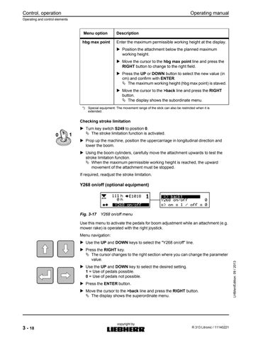
hbg max point (4)
Y268 on/off (5)
stick limit (6)
Super Finish. Adjustment of flow reduction for Super Finish function
Adjustment of slewing gear torque (sensitivity)
Display of operating hours of individual machine components
Status display of individual inputs and outputs
Display of software version
Activation of an attachment with hydraulic cylinder (e.g. mower rake)
Electronic stroke limitation for the restriction of the moving range of the boom
Use of foot pedals for the adjustment of the boom while the attachment is operated with the right joystick
Electronic stick shut-down for the restriction of the moving range of the stick
(1)only in conjunction with "Tool Control" or "Tool Control Plus" (optional equipment)
(2)only in connection with "Tool Control Plus" (optional equipment)
(3)only in connection with "Tool Control Plus" and "Tool Permanent" (optional equipment)
(4)only in connection with "Stroke limitation" (optional equipment)
(5)only in connection with "Control switchover" or "Tool Permanent" (optional equipment)
(6)only in connection with "Stick cylinder shut-down" (optional equipment)
Tab. 3-1 Explanation of submenus
Operating manual R 313 Litronic / 11140221 Operating and control elements 3 - 11
operation MJFCIFSS copyright by
Control,
3.1.5.1Description of the submenus Tool Option
This menu is used to select pre-set pressure and flow reductions to the working tools (activation of foot pedals, e.g. for hydraulic hammer or grapple). Prior to using the working tools, the correct option for the working tool must be selected at the display.
Caution!
Incorrect pressure or flow reduction settings may result in damage to the working tool (e.g. hydraulic hammer) or impair its functions (e.g. mill). Select the correct option before using the working tools.
Menu navigation:
Move the cursor down with the DOWN key, until the desired working tool is selected (options 1 to 10) and then press the ENTER key. The working tool is selected.
Note!
On request, LIEBHERR and the customer service department will pre--set the desired options and label them with the names of the associated tools, e.g. "hammer" or "grapple".
Contact us to have the menu for each working tool set up.
Control, operation 3 - 12 Operating manual Operating and control elements R 313 Litronic / 11140221 MJFCIFSS copyright by
Fig. 3-8 Tool Option menu (figure shows menu with Tool Control Plus)
3-9 SF-Flow menu
This menu allows you to adjust the flow reduction (SF-Flow) for the Super Finish function. With the Super Finish function, the movement of the attachment can be slowed down, so that tasks can be carried out with greater precision.
Adjustment range: 0% (max. flow reduction) to 100% (no reduction).
Menu navigation:
Use the UP and DOWN keys to select the desired reduction. Press the RIGHT key to confirm your selection. The SF-Flow settings are selected.
Actuate the SF switch on the A console. The respective menu is shown on the display.
Torque Slew
3-10 Torque Slew menu
In this menu, you can adjust the sensitivity of the slewing gear. These settings determine the accuracy with which the uppercarriage can be positioned. The acceleration of the uppercarriage is determined by the distance by which the joystick handle is moved and the set sensitivity of the drive. The swivelling movement can be set to slow or fast (direct propulsion).
The set sensitivity remains active when the menu is closed and cannot be deactivated or activated without accessing the menu again.
Adjustment range: 0 (very slow) to 100 (fast).
Menu navigation:
Use the UP and DOWN keys to select the desired movement speed. Press the RIGHT key to confirm your selection. The desired torque slew is now set.
Operating manual R 313 Litronic / 11140221 Operating and control elements 3 - 13 Control, operation MJFCIFSS copyright by SF-Flow
Fig.
Fig.
Fig. 3-11 Info hours menu
The menu shows the operating hours of individual machine components.
hours-day: Daily operating hours counter (can be reset with ENTER key).
hours-rpm: Operating hours of three speed ranges (low, medium, high)
hours-sensor: Operating hours with "automatic speed adjustment" during which the respective pilot control units were used.
hours-drive: Operating hours in travel mode
sensor control: Adjustment of time after (in seconds) which the diesel engine is automatically slowed to idle speed, if no pilot control unit has been actuated.
Menu navigation:
Use the UP and DOWN keys to select the desired submenu (black bar).
Press the ENTER key to confirm your selection. The display shows the selected submenu. Press the RIGHT key. The display shows the subordinate menu.
3 - 14 Operating manual Operating and control elements R 313 Litronic / 11140221 MJFCIFSS copyright by Info hours
Control, operation
The menu shows the status of individual inputs and outputs of the control system.
IO-Master: control system (master); values of inputs and outputs
IO-Slave: control system (slave); values of inputs and outputs
var-master: control system (master); variables and operating data
Menu navigation:
Use the UP and DOWN keys to select the desired submenu (black bar).
Press the ENTER key to confirm your selection. The display shows the selected submenu. Press the RIGHT key.
Info Software
The menu shows the software versions used.
M: Master control version/ S: Slave control version/ D: Display control version.
Menu navigation: Press the RIGHT key. The display shows the subordinate menu.
Cyl. extern (optional equipment)
Operating manual R 313 Litronic / 11140221 Operating and control elements 3 - 15 Control, operation MJFCIFSS copyright by Info I / O
Fig. 3-12 Info I / O menu
Fig. 3-13 Info Software menu
Fig. 3-14 Cyl. extern menu
Control, operation
Operating and control elements
This menu is used to activate the application of an attachment with hydraulic cylinder (e.g. mower rake).
Menu navigation:
Use the UP and DOWN keys to select the "cylinder extern" line. Press the RIGHT key. The cursor changes to the right section where you can change the parameter value.
Use the UP and DOWN key to select the desired setting.
1 = Use of attachment possible.
0 = Use of attachment not possible. Press the ENTER button.
Move the cursor to the >back line and press the RIGHT button. The display shows the superordinate menu.
Hbg max point (optional equipment)
In situations where the machine's working space is limited in the vertical direction (e.g. by power transmission lines), it may be helpful to use stroke limitation to predefine a max. working height.
Danger!
Risk of injury and damage to equipment!
During the adjustment of the stroke limitation, there is a risk of serious damage and injury, as the equipment might collide with another object.
When adjusting the limitation function, operate the machine with exceptional care.
Setting stroke limitation:
1 Obstacle (e.g. tunnel roof, overhead power line)
2 Safety margin, as prescribed
m Max. working height (shut-off point)
The maximum permissible working height m must be at a sufficient distance to the object 1 that limits the vertical movement of the machine.
For the adjustment of the shut-off point, the machine must be properly supported. The settings are shown at the display in the hbg max point submenu:
3 - 16
Operating manual
R 313 Litronic / 11140221 MJFCIFSS copyright by
Fig. 3-15 Attachment at max. working height - example:
*Values in cm
There are two methods to set stroke limitation:
Menu optionDescription
teach point Saves the current position of the working attachment as the maximum permissible working height.
Move the stick upwards and fully tilt the digging bucket (if attached).
Move the attachment to the desired maximum working height.
Move the cursor to the teach point line and press the RIGHT key to change to the right field.
Press the UP button to enter the value "1" and confirm with ENTER
The current working height (act. max. point) is saves as the maximum permissible working height (hbg max point).
Move the cursor to the >back line and press the RIGHT button.
The display shows the subordinate menu.
Operating manual R 313 Litronic / 11140221 Operating and control elements 3 - 17 Control, operation MJFCIFSS copyright by
Fig. 3-16hbg max point* menu
Control, operation
hbg max point
Enter the maximum permissible working height at the display. Position the attachment below the planned maximum working height.
Move the cursor to the hbg max point line and press the RIGHT button to change to the right field.
Press the UP or DOWN button to select the new value (in cm) and confirm with ENTER
The maximum working height (hbg max point) is staved. Move the cursor to the >back line and press the RIGHT button.
The display shows the subordinate menu.
*)Special equipment: The movement range of the stick can also be restricted when it is extended.
Checking stroke limitation
Turn key switch S249 to position 0 The stroke limitation function is activated. Prop up the machine, position the uppercarriage in longitudinal direction and lower the boom.
Using the boom cylinders, carefully move the attachment upwards to test the stroke limitation function. When the maximum permissible working height is reached, the upward movement of the attachment must be stopped. If required, readjust the stroke limitation.
Y268 on/off (optional equipment)
Use this menu to activate the pedals for boom adjustment while an attachment (e.g. mower rake) is operated with the right joystick.
Menu navigation:
Use the UP and DOWN keys to select the "Y268 on/off" line.
Press the RIGHT key.
The cursor changes to the right section where you can change the parameter value.
Use the UP and DOWN key to select the desired setting.
1 = Use of pedals possible.
0 = Use of pedals not possible.
Press the ENTER button.
Move the cursor to the >back line and press the RIGHT button. The display shows the superordinate menu.
3 - 18 Operating manual Operating and control elements R 313 Litronic / 11140221 MJFCIFSS copyright by
Fig. 3-17 Y268 on/off menu
Menu
optionDescription
Stick limit (optional equipment)
This means that the stick can only be moved within a preset angle range (defined by a minimum and a maximum angle). The reach of the attachment thus depends on the stick cylinder shut-down point and the angle of the boom.
Danger!
Risk of injury and damage to equipment!
During the adjustment of stick cylinder shut-down, there is a risk that the attachment might collide with the operator's cab.
When adjusting the limitation function, operate the machine with extreme caution.
Settings in menus "stl max point" and "stl min point":
ValueStick position
0 (min)Stick fully extended
500Stick in centre position
1000 (max)Stick fully retracted
Operating manual R 313 Litronic / 11140221 Operating and control elements 3 - 19
operation MJFCIFSS copyright by
Control,
Fig. 3-18 Menu stick limit
Fig. 3-19 Settings
Control, operation
The stick cylinder shut-down can be adjusted in various ways, depending on the equipment of the machine:
Menu optionDescription
teach max Saving of current stick position as the maximum permissible stock position for retraction of the stick.
Move the attachment to its highest position.
Carefully retract the stick with the respective attachment (e.g. grapple) to the desired position.
Move the cursor to the teach max line and press the RIGHT key to change to the right field.
Press the UP button to enter the value "1" and confirm with ENTER
The current stick position (act. position) is stored as the maximum permissible stick position (stl max point).
Move the cursor to the >back line and press the RIGHT button.
The display shows the subordinate menu.
stl max point Enter the maximum permissible stock position for retraction of the stick.
Position the stick within the planned range of movement.
Move the cursor to the stl max point line and press the RIGHT button to change to the right field.
Press the UP or DOWN button to select the new value and confirm with ENTER
The maximum permissible stick position for retraction is saved.
Move the cursor to the >back line and press the RIGHT button.
The display shows the subordinate menu.
teach min Saving of current stick position as the maximum permissible stock position for extension of the stick *).
Carefully retract the stick with the respective attachment (e.g. grapple) to the desired position.
Move the cursor to the teach min line and press the RIGHT key to change to the right field.
Press the UP button to enter the value "1" and confirm with ENTER
The current stick position (act. position) is stored as the maximum permissible stick position (stl min point).
Move the cursor to the >back line and press the RIGHT button.
The display shows the subordinate menu.
3 - 20 Operating manual
and control elements R 313 Litronic / 11140221 MJFCIFSS copyright by
Operating
Menu
stl min point Enter the maximum permissible stock position for extension of the stick *)
Position the stick within the planned range of movement.
Move the cursor to the stl min point line and press the RIGHT button to change to the right field.
Press the UP or DOWN button to select the new value and confirm with ENTER
The maximum permissible stick position for extension is saved.
Move the cursor to the >back line and press the RIGHT button.
The display shows the subordinate menu.
*)Special equipment: The movement range of the stick can also be restricted when it is extended.
Checking stick cylinder shut-down:
Carefully extend and retract the stick to check the stick shut-down function. When the set shut-down positions are reached, the stick movement must be automatically stopped.
If required, readjust the stick cylinder shut-down.
3.2Control
3.2.1Entering and exiting the operator's cab
Caution!
Risk of injury when operator's cab is entered or exited without due regard to the safety instructions!
When entering and exiting the operator's cab, ensure that the safety lever is in its top position.
Always access and descend from the machine using the provided climbing aids. Ensure that your body is resting on at least 3 points: Hold on to the machine with both hands when raising a foot, and stand on both feet when letting go with one hand.
Do not use operating elements as handles.
Never jump from the machine.
Operating manual R 313 Litronic / 11140221 Control 3 - 21 Control, operation MJFCIFSS copyright by
optionDescription
3.2.1.1Mounting and dismounting from the machine
Mount the machine/dismount from the machine facing it (figure to the right).
3.2.1.2Entering and exiting operator's cab
Entering cab:
Press the lock at the door handle 1 and open the door.
If you wish to leave the door open, open it fully (swivel by 180° backwards) and secure it with the locking mechanism 2
Always enter the cab facing the machine, and sit down on the operator seat.
If necessary, adjust the operator seat and steering column.
Exiting cab:
Shut down the machine and push the safety lever upwards.
Push down the door handle 3 at the door lock.
Open the door fully and secure it with the locking mechanism 2 Face the machine when descending from it.
Control, operation 3 - 22 Operating manual Control R 313 Litronic / 11140221 MJFCIFSS copyright by
Fig. 3-20 Ascending using climbing aids
Fig. 3-21 Operator’s cab
1 Door handle
3 Inside door handle
2 Locking mechanism
4 Lever of locking mechanism
Releasing door locking mechanism:
The door is secured with the locking mechanism 2 Move the lever 4 beside the operator's cab frame outwards. The door is now released. Close the door.
3.2.2Safety lever
Fig. 3-22 Safety lever
To prevent inadvertent movements of the machine, the left control console is equipped with a safety lever.
Caution!
When entering or exiting the operator's cab, always ensure that the safety lever is in its top position (arrow).
When the safety lever is tilted up, a number of machine functions are disabled or otherwise modified:
–Actuation of the pilot control units (e.g.joysticks or pedals) does not result in movement of the machine.
–The slewing gear brake is applied.
–It is now not possible to release the slewing gear brake.
By moving the safety lever to its bottom position, the initial switching statuses are reestablished, and the pilot control units are enabled.
Before commencing work with the machine, take place on the operator's seat and move the safety lever to its bottom position.
3.2.3Operator seat
Danger!
The adjustment of the operator seat could result in an inadvertent actuation of control elements, moving the machine or the attachment. This can lead to injury to persons or damage to property.
Therefore do not adjust the seat while the engine is running.
Before adjusting the operator seat, fold the safety lever upwards.
Operating manual R 313 Litronic / 11140221 Control 3 - 23 Control, operation MJFCIFSS copyright by
3.2.3.1Adjusting the seat suspension
Control, operation 3 - 24 Operating manual Control R 313 Litronic / 11140221 MJFCIFSS copyright by
Fig. 3-23 Operator seat with mechanical spring mechanism (left) or pneumatic suspension (right)
Seats with mechanical spring mechanism: Adjust the seat to the body weight, turning the handle 1 The indicator beside the handle indicates the set body weight. 1 Operator seat heating 2 Lumbar support 3 Backrest adjustment 4 Hand wheel for the adjustment of the armrest angle 5 Horizontal adjustment 6 Horizontal suspension (optional equipment) 7 Horizontal adjustment with control console 8 Weight adjustment 9 Height adjustment 10 Shock absorber 11 Seat depth adjustment 12 Seat angle adjustment 13 Safety belt sign
Fig. 3-24 Adjustment of seat suspension for seats with mechanical spring mechanism (left) or pneumatic suspension (right)
Seats with pneumatic suspension: Before adjusting the height, set the shock absorber to "soft".
Sit down on the seat.
Pull the lever 1 briefly upwards. The seat is automatically adjusted to suit the body weight of the operator.
3.2.3.2Adjusting seat height
Seats with mechanical spring mechanism: The seat can be adjusted at various height levels.
Caution!
To adjust the seat height, pull it up with both hands. Danger! The hands could become squeezed between the seat and the control consoles. Do not reach below the seat surface from the side to move it from its top to its bottom position.
To lift the seat, place both hands under the front part of the seat. When pushing the seat down, hold it firmly.
Lift the seat to the desired height and ensure that it engages properly in this position.
If the seat is lifted to a position above the last step (stop), it is lowered automatically to its lowest position.
Seats with pneumatic suspension:
The seat height can be adjusted steplessly by means of compressed air and a compressor. If the upper or lower stops are reached, the height is automatically adjusted near that position to provide minimum suspension travel. To prevent damage to the equipment, do not let the compressor run for longer than 1 minute.
Before adjusting the height, set the shock absorber to "soft".
Adjust the seat height by pulling or pushing the lever 1 to the respective stop.
Operating manual R 313 Litronic / 11140221 Control 3 - 25 Control, operation MJFCIFSS copyright by
Fig. 3-25 Adjustment of seat height for seats with mechanical spring mechanism (left) or pneumatic suspension (right)
3.2.3.3Adjusting horizontal seat position
Pull the lever 1 and move the seat into a horizontal position.
Pull the lever 2 and move the seat together with the control consoles horizontally.
3.2.3.4Adjusting seat angle
Lift the button 1
Sit on the seat and move it to the desired angle.
3.2.3.5Adjusting seat depth
Lift the button 1
Control, operation 3 - 26 Operating manual Control R 313 Litronic / 11140221 MJFCIFSS copyright by
Fig. 3-26 Adjustment of horizontal seat position for seats with mechanical spring mechanism (left) or pneumatic suspension (right)
Fig. 3-27 Adjustment of seat angle
Fig. 3-28 Adjustment of seat depth
Sit on the seat and move it to the desired position.
3.2.3.6Adjusting backrest
Fig. 3-29 Adjustment of backrest
Pull up the locking lever 1
Sit on the seat and move the backrest to the desired position. Release the locking lever. Ensure that the locking lever engages in the desired position and that the backrest cannot be moved to another position.
3.2.3.7Adjusting lumbar support
Adjustment of lumbar support
Only for seats with pneumatic suspension: Adjust the shape of the lumbar support by pressing the button 1 at the rear side of the seat.
Operating manual R 313 Litronic / 11140221 Control 3 - 27 Control, operation MJFCIFSS copyright by
Fig. 3-30
3.2.3.8Adjusting shock absorption
Adjustment of shock absorption
Only for seats with pneumatic suspension: The shock absorption level can be adjusted to suit the road or terrain conditions. Turn the handle 1 to the desired position and release it. Position 1 = hard Position 2 = medium Position 3 = soft
3.2.3.9Adjusting horizontal shock absorption mechanism (optional equipment)
Adjustment of horizontal shock absorption mechanism
Only for seats with pneumatic suspension: Under certain operating conditions (e.g. travelling with trailer), operator comfort can be increased by actuating the horizontal shock absorption. Move the handle 1 to the desired position. Position 1 = horizontal shock absorption OFF Position 2 = horizontal shock absorption ON
Control, operation 3 - 28 Operating manual Control R 313 Litronic / 11140221 MJFCIFSS copyright by
Fig. 3-31
Fig. 3-32
3.2.3.10Adjusting armrests
Adjustment of armrest angle
Adjusting the armrest angle: Turn the hand wheel 1 until the armrests are in the desired position.
Adjusting armrest height: The armrests can be folded back and adjusted individually in height.
Adjustment of armrest height:
Remove the cover cap 1 from the seat covering. Loosen the hex nut 2 (wrench size 13 mm). Set the armrest to the desired position.
Tighten the hex nut.
Replace the cover cap on the hex nut.
Operating manual R 313 Litronic / 11140221 Control 3 - 29 Control, operation MJFCIFSS copyright by
Fig. 3-33
Fig. 3-34
3.2.3.11Adjusting headrest (optional equipment)
Adjustment of head rest
Adjusting head rest:
Adjust the head rest by pulling it from the engaging mechanism. Adjust the headrest angle by pushing it forward or back.
Removing headrest:
Move the headrest to the upper stop and then pull it sharply from the seat.
3.2.3.12Seat heating (optional equipment)
Actuate the switch 1 to switch on the seat heating.
Control, operation 3 - 30 Operating manual Control R 313 Litronic / 11140221 MJFCIFSS copyright by
Fig. 3-35
Fig. 3-36 Seat heating
3.2.3.13Wearing/taking off safety belt
3-37 Seat belt
The safety belt is an inertia seat belt. It is thus not necessary to adjust the belt length. Pull the belt 1 from the reeling mechanism 2. When the belt is pulled with a jerk, it might lock. Push the locking piece into the buckle 3 so that it engages.
Danger!
The seat belt is designed to protect the machine operator. Prior to starting the machine, put on the seat belt. Ensure that the seat belt is not twisted.
To ensure proper safety, regularly check the seat belt and replace it without delay if you detect any damage to parts.
To open the buckle 4, push the lock button down, using your thumb. The reeling mechanism 1 automatically pulls in the belt.
3.2.4Operator seat
Danger!
The adjustment of the operator seat could result in an inadvertent actuation of control elements, moving the machine or the attachment. This can lead to injury to persons or damage to property. Do not adjust the operator seat while driving the machine. Park the machine and apply the parking brake. Move the safety lever up.
Operating manual R 313 Litronic / 11140221 Control 3 - 31 Control, operation MJFCIFSS copyright by
Fig.
If
Control, operation 3 - 32 Operating manual Control R 313 Litronic / 11140221 MJFCIFSS copyright by
Model variant Adjusting seat to body weight/seat height (in models with manual adjusting mechanism):
down on the seat. Adjust the seat height/body weight by pulling or pushing the lever 9 to the stop. Check the display 8 •green = settings correct •yellow = correction required
Fig. 3-38 Operator seat
*
Sit
necessary: Adjust the settings by pulling or pushing the lever 9 to the stop. 1 Operator seat heating 2 Mechanical / pneumatic lumbar support* 3 Backrest adjustment 4 Armrest height adjustment 5 Armrest adjusting wheel 6 Horizontal suspension* 7 Horizontal adjustment with control consoles 8 Display for weight settings* 9 Manual/automatic adjustment for body weight and seat height* 10 Shock absorber* 11 Horizontal adjustment 12 Seat depth 13 Seat inclination 14 Safety belt 15 Armrests 16 Headrest
Adjusting seat to body weight (in models with automatic adjusting mechanism)*:
Before adjusting the body weight settings, set the shock absorber* to "soft". Sit down on the seat.
Pull the lever 9 briefly upwards. The seat is automatically adjusted to suit the body weight of the operator.
Adjusting seat height (in models with automatic adjusting mechanism)*: Before adjusting the height, set the shock absorber to "soft".
Caution!
Risk of damage to compressor. Do not run the compressor continuously for more than 1 minute.
Adjust the seat height by pulling or pushing the lever 9 to the stop.
Adjusting seat depth:
Lift the button 12
Sit on the seat and move it horizontally to the desired position. To adjust the angle of inclination of the seat, press the button 13 Sit on the seat and move it to the desired angle.
Horizontal adjustment:
Pull up the lever 11
Adjust the operator seat in horizontal direction. Release the lever. Ensure that the lever engages properly in the desired position (audible click).
Carry out the following check: After locking, it must be impossible to move the operator seat to a different position.
Horizontal adjustment with control consoles:
Pull up the lever 7
Adjust the operator seat together with the control consoles in horizontal direction. Release the lever. Ensure that the lever engages properly in the desired position (audible click).
Carry out the following check: After locking, it must be impossible to move the operator seat to a different position.
Adjusting backrest:
Pull up the lever 3
Sit on the seat and move the backrest to the desired position. Release the lever. Ensure that the locking lever engages in the desired position. Carry out the following check: After locking, it must be impossible to move the backrest to a different position.
Operating manual R 313 Litronic / 11140221 Control 3 - 33 Control, operation MJFCIFSS copyright by
Adjusting lumbar support (in models with mechanical adjusting mechanism):
Adjust the height and curve of the lumbar pad by turning the hand wheel 2 at the back of the seat.
Adjusting lumbar support (in models with pneumatic adjusting mechanism)*:
Adjust the curve of the upper and lower section of the backrest upholstery by pressing the two switches 2 at the rear of the seat.
Adjusting shock absorber*:
The shock absorption level can be adjusted to suit the actual road or terrain conditions.
Turn the handle 10 to the desired position and release it.
•Position1 = hard
•Position2 = medium
•Position3 = soft
Adjusting horizontal cushioning*:
Under certain operating conditions, you can improve the operator comfort by adjusting the horizontal cushioning mechanism. This helps reduce impact stress in travel direction on the operator as these impacts are better cushioned by the seat.
Move the handle 6 to the desired position.
•Position1 = horizontal cushioning OFF
•Position2 = horizontal cushioning ON
After the handle has been moved to position 1, ensure that is engages properly in this position: push the seat back until you hear an audible click.
Adjusting armrests:
Turn the hand wheel 5 until the armrests are in the desired position. If required, the height can be adjusted individually for each armrest:
Remove the cover cap 4 from the seat covering.
Loosen the hex (wrench size 13mm).
Set the armrest to the desired position.
Tighten the hex nut (25Nm).
Replace the cover cap on the hex nut.
Adjusting headrest:
Adjust the headrest 16 by pulling it from the engaging mechanism. Adjust the headrest angle by pushing it forward or back.
To remove the headrest, move it to the upper stop and then pull it with force from the seat.
Seat heating:
Actuate the switch 1 to switch on the seat heating.
•Position0 = seat heating OFF
•Position1 = seat heating ON
* Model variant
operation 3 - 34 Operating manual Control R 313 Litronic / 11140221 MJFCIFSS copyright by
Control,
3.2.5Windscreen
1 Locking lever
2 Handle bracket
The windscreen can be placed to 2 positions.
–Position a: Windscreen closed.
–Position b: Windscreen is fully opened (attached to the roof of the operator's cab).
Caution!
The windscreen is very heavy.
There is a risk of injury to fingers, if they become caught between the panel and the frame when closing the windscreen.
Hold the windscreen with both hands by the handle brackets 2
Caution!
Risk of glass break. The windscreen might break, if it is allowed to drop without support.
Hold the windscreen with both hands by the handle brackets 2
Opening windscreen:
Pull the latch 1 inwards and down. The windscreen is released.
Hold the windscreen by the two brackets and slide it upwards until it engages. Lock the windscreen in its position by engaging the latch 1
Closing windscreen:
Pull the latch 1 inwards and forward. The windscreen is released.
Hold the windscreen by the two handle brackets and slide it carefully down until it engages.
Operating manual R 313 Litronic / 11140221 Control 3 - 35 Control, operation MJFCIFSS copyright by
Fig. 3-39 Windscreen
Lock the windscreen in its position by engaging the latch 1.
3.2.6Sun blind
Sun blinds for windscreen and cab roof
The operator's cab is equipped with two sun blinds, one for the windscreen and one for the glass panel in the cab roof.
Windscreen
Pull the sun blind down, holding it by the cross bar 1 The sun blind can be individually adjusted. Press the switch 2 (red). The sun blind is automatically rolled up.
Cab roof
Pull out the sun blind and engage it in the holders provided. To open the sun blind, remove it from the holders and let it roll up slowly.
3.2.7Emergency exit through rear window
Fig.
Emergency exit through rear window
Pull the latch 1 at the inside of the rear window to remove the rubber seal 2
Control, operation 3 - 36 Operating manual Control R 313 Litronic / 11140221 MJFCIFSS copyright by
Fig. 3-40
3-41
In the event of an emergency, pull out the rubber seal 2 along the entire circumference of the rear window panel and push out the window.

3.2.8Inside lighting
The inside lighting is switched on/off by a rocker switch. Set the rocker switch to position 1 The light is switched on. Set the rocker switch to position 0 The light is switched off. Switch position 2 is not assigned a function.
3.2.9Fire extinguisher (optional equipment)*
*Operator instructions
Operating manual R 313 Litronic / 11140221 Control 3 - 37 Control, operation MJFCIFSS copyright by
Fig. 3-42 Inside lighting
Fig. 3-43 Fire extinguisher / first aid kit
The hook for the fire extinguisher is located in a recess in the bottom right corner of the operator's cab.
3.2.10Windshield wiper
3.2.10.1Windshield wiper
With the ignition turned on, press switch S14 on control panel C to activate the windshield wiper operation. This switch has two settings:
Push the switch in position 1 down (center position). Continuous operation is activated.
Push the switch in position 2 down (final position). Intermittent control is activated.
3.2.10.2Window washer system
With the ignition turned on, press switch S11 on control panel C fo activate the windshield washer system.
Press the button down and hold. Water will be sprayed onto the front windshield through nozzles. The windshield wiper runs continuously.
Release the button. The water flow stops. The windshield wiper continues to run continuously for approx. 3 seconds.
3.2.10.3Windshield washing fluid container
3-44 Windshield washing fluid container
The container for the windshield washing fluid is located at the rear of the cab. Open the cover (see arrow) to refill the container with commercially available windshield washing fluid.
Quantity: see Lubrication Chart
Control, operation 3 - 38 Operating manual Control R 313 Litronic / 11140221 MJFCIFSS copyright by
Fig.
3.2.10.4Window wiper on cab roof
With the ignition turned on, press switch S14 on control panel C to activate the windshield wiper operation. This switch has two settings: Push the switch in position 1 down (center position). Continuous operation is activated. Push the switch down to position 2 and hold (final position). Water will be sprayed on the windshield. The windshield wiper runs continuously.
3.2.11Lighting
Operating manual R 313 Litronic / 11140221 Control 3 - 39 Control, operation MJFCIFSS copyright by
Fig. 3-45 Window wiper on cab roof
Fig. 3-46 Arrangement of the lighting devices
1 Parking and travel light
3 Roof light (optional equipment)
2 Attachment headlight
4 Beacon (optional equipment)
The switches for the lighting devices are located on the control console C.
Parking and lower beam headlight
When the ignition is on or off, the parking and lower beam headlight can be switched on with the switch S61
–1. (centre position): parking light on.
–2. (limit position): travel light on.
Front attachment headlight, front roof light (optional equipment)
When the ignition is on, the roof light and the attachment headlight can be switched on with the switch S22
–1. (centre position): Attachment light on.
–2. (limit position): attachment headlight and roof light on.
Rear headlight (optional equipment)
When the ignition is on, the rear work light can be switched on with the switch S22-1
–1. (centre position): no function (standard equipment).
–2. (limit position): rear roof light and the rear work light on.
Beacon (optional equipment)
When the ignition is on, the beacon can be switched on with the switch S41
3.2.12Heating system
The operator's cab is equipped with a heating system as standard. The heating system can be used to heat or ventilate the operator's cab. The switch of the heating system is located on the control console B
Control, operation 3 - 40 Operating manual Control R 313 Litronic / 11140221 MJFCIFSS copyright by
S92 Air distribution in legroom S318 A/c system*
S93 Heating output S398 Switching of blower air output
S284 Blower output
* optional equipment
A Legroom, front windscreen C Rear of cab
B Legroom, operator's seat
Adjusting blower output:
The output of the blower is adjusted by means of the rotary switch S284
Position 0: The blower is switched off.
Operating manual R 313 Litronic / 11140221 Control 3 - 41 Control, operation MJFCIFSS copyright by
Fig. 3-47 Operation of the air-conditioning system
Fig. 3-48 Overview of air outlets in the operator's cab
Positions 1 to 4: The blower motor can be run at 4 different speeds.
Changing air outlet:
Use the switch S398 to choose whether the air is to be let out in the legroom (A and B) or at the rear of the cab C
Press the switch down.
The air flow from the blower is fed through the ventilation openings in the legroom (A and B).
The indicator light in the switch is on.
Press the switch up.
The air flow from the blower is fed through the ventilation openings in the rear panel of the cab C
The indicator light in the switch is off.
Adjusting air distribution in the legroom:
This rotary switch S92 is used to adjust the air distribution in the legroom.
The air is fed to the legroom (reverse switch light is on).
Turn the rotary switch to the left. The air is blown through the openings 1 (windscreen).
Turn the rotary switch S92 to the right. The air is blown through the openings 2 (operator's seat).
If the rotary switch is set to an intermediate position, the air is distributed between the two openings 1 and 2
Adjusting heating output:
Turn the rotary switch S93 to adjust the heating output.
The diesel engine must be on.
Turn the rotary switch S93 to the left. The heating output is reduced. When the switch is in position "0" (left stop), the heating is switched off. Turn the rotary switch S93 to the right. The heating output is increased.
Note!
In order to achieve optimum comfort in the cab, we recommend feeding the air through the openings in the legroom (A and B).
3.2.13A/c system (optional equipment)
On request, the machine can be equipped with an a/c system. The a/c system is activated by means of the switch S318
The diesel engine must be on.
Press the switch S318 down. The a/c system is active. The indicator light in the switch is on.
Press the switch S18 up. The a/c system is off. The indicator light in the switch is off.
Control, operation 3 - 42 Operating manual Control R 313 Litronic / 11140221 MJFCIFSS copyright by
If the rotary switch S284 (blower output) is in position 0 when the a/c system is switched on, the blower speed is automatically set to 1
During a/c operation, the blower air is cooled. Use the rotary switch S93 (heating) to adjust the room temperature. The blower air is coolest when the rotary switch S93 is in position 0 (left stop).
In order to dehumidify the cab, switch on the a/c system while the system is in heating mode. Switch off the a/c system when all windows are completely defogged.
Note!
In order to achieve optimum comfort in the cab with a/c operation, we recommend feeding the air through the openings at the rear of the cab ( C).
3.3Operation
3.3.1Safety instructions
3.3.1.1Bringing the machine into service
–Before starting the machine, perform a thorough walkaround inspection.
–Visually check the machine for loose bolts, cracks, wear, leaks and damage.
–Never start or operate a damaged machine.
–Make sure to correct any problems immediately.
–Verify that all hoods, covers and doors are closed, however, the locks should remain unlocked.
–Verify that all safety signs are in place.
–Make sure that all windows, as well as the inside and outside mirrors are clean. Secure all doors and windows to prevent unintentional movement.
–Before operating the machine, adjust the operator’s seat, the mirror, the armrests and the other items to ensure comfortable and safe working conditions.
–The noise protection devices on the machine must be in working order.
–Never operate the machine without the cab.
3.3.1.2Starting the machine
–Before start up, check all indicator lights and instruments for proper function, bring all controls into neutral position and insure that the safety lever is in the raised position.
–Blow the horn briefly prior to starting the diesel engine, in order to warn persons located near the machine.
–Only start the machine from the driver’s seat.
–Start the diesel engine according to the regulations in the operating instructions, if you have not received any other instructions.
–Lower the safety lever and check all indicators, gauges, warning devices and controls for their proper indication.
–Only operate the diesel engine in a well-ventilated area, if the area is enclosed. If necessary, open doors and windows in the building to provide ample fresh air.
–Bring the engine and hydraulic oil to operating temperature. Low oil temperatures cause aslow reaction of the controls.
Operating manual R 313 Litronic / 11140221 Operation 3 - 43 Control, operation MJFCIFSS copyright by
–Check that all attachment functions are operating properly.
–Carefully take the machine to an open area and check all control functions.
3.3.1.3Shutting down the machine
–Park the machine on level and stable ground whenever possible. Otherwise, chock or block wheels when parking on a slope.
–Lower the attachment so that it rests on the ground.
–Move all control elements into the neutral position. Set the parking and slewing gear brake.
–Switch off the diesel engine according to the operating instructions and move the safety lever up, prior to leaving the driver’s seat.
–Lock the machine, as well as all hoods, covers and doors; remove all keys and secure the machine against any unauthorized use.
3.3.1.4Towing the machine
–Always observe the correct procedure: See chapter “Towing the machine” in this operating manual.
–The machine may only be towed in exceptional circumstances, such as moving a disabled machine from a hazardous location.
–Before pulling or towing the machine, check all cables, hooks and couplers for safety and stability.
–Towing equipment must have sufficient tensile strength and must be attached to the undercarriage at the designated tiedown attachment points.
–Never allow anyone to remain in the area of the towing devices.
–During the towing procedure, keep within the required transport position, the permissible speed and distance.
–Proceed as outlined in the operating manual when putting the machine back into service.
3.3.2To see and to be seen
3.3.2.1Field of vision
As a machine operator, most information you need for safe working is acquired through vision. Good sight and a large field of vision help effectively minimise risks to you and others when driving the machine and working with it.
As not all areas around the machine can be seen directly from the operator's cab, the machine is equipped with a number of visual aids (e.g. mirrors and cameras). These aids are used to monitor areas around the machine that are not directly visible to the operator.
Caution!
Certain attachments and tools can restrict the view of the machine operator. Risk of accident!
Be aware of these restrictions to your view and the existence of dead angles. If required, avail of a signaller to guide you.
Observe the applicable statutory regulations for visibility from the operator's cab. For member states of the European Economic Area, ISO 5006:2006 specifies a static
operation 3 - 44 Operating manual Operation R 313 Litronic / 11140221 MJFCIFSS copyright by
Control,
test method for determining and evaluating the machine operator's visibility. The field of vision is thereby assessed with the standard equipment of the machine. In principle, changes to machine, such as the attachment or removal of components, must not affect the field of vision. If such changes however do affe ct visibility, a test according to ISO 5006:2006 or according to the regulations applicable at the site of operation must e carried out. Depending on the result of the test, certain measures might need to be taken. The machine operator must always be informed of any such changes to the machine.
3.3.2.2Measures to be taken prior to and during operation
Ensure that all persons establish contact with the machine operator before approaching the machine.
Regularly check all visual aids for dirt, correct adjustment and proper functioning. Adjust visual aids so that they provide the largest possible field of vision around the machine.
Keep visual aids and the windows of the operator's cab clean at all times. Repair or replace defective visual aids without delay.
Do not use visors, if they obstruct your view.
Always keep an eye on the area around the machine so that you can spot potential dangers in advance.
Avoid reversing wherever possible.
Direct vision is always safest: plan your work so that you can properly see the working area without any obstructions to your view.
When working with restricted visibility or if visual aids are defective, always work with a signaller. Agree hand signs. For especially difficult tasks, establish voice contact (e.g. via radio).
When visibility is poor, use the lights according to the applicable statutory regulations.
3.3.3Camera system (optional equipment)
Due to the machine design and dimensions, the field of vision from the operator's cab might be somewhat restricted. The camera system is designed to increase the field of vision of the operator and is installed in addition to the mirrors. The machine operator can thus see areas that are not directly visible from the cab. The monitor in the operator's cab shows the image captured by the camera.
Danger!
The camera system is only an aid and might not capture certain obstacles. In addition, the image might be slightly distorted. It does not warn the operator if there are persons or obstacles in the danger area.
Please note:
–It is the responsibility of the machine operator to monitor the working area and the path of travel of the machine.
–In the event of a failure of the camera system, the machine must be moved and operated with the aid of a signaller.
For detailed information, refer to the operating manual of the camera manufacturer.
Operating manual R 313 Litronic / 11140221 Operation 3 - 45 Control, operation MJFCIFSS copyright by
3.3.4Starting machine
3.3.4.1General instructions
Note!
When using the machine above a certain height above sea level and at low ambient temperatures, the performance and the service life of the diesel engine with turbo charger is considerably reduced. Under such conditions, there is an increased risk of overheating of the coolant circuit and the hydraulic oil.
To prevent damage to the diesel engine, the output of the engine is automatically in line with the elevation above sea level and the ambient temperature. Simultaneously observe the coolant circuit and the hydraulic oil cooling system.
3.3.4.2Tasks to be completed prior to machine start
Caution!
A fire can only be extinguished, if it is accessible. Before starting the machine, open all locks of the hydraulic excavators panels. In the event of a fire, these doors can than be opened without delay to extinguish the fire.
Position of the locks: see chapter "Maintenance".
Caution!
When the tasks listed below are completed and the machine is already at operating temperature, there is risk of injury from scalding by hot coolant or oil.
Before completing the tasks described below, read the respective sections in chapter "Maintenance".
Before starting the machine, carry out the following routine procedure:
–Check oil level in engine*.
–Check coolant level of diesel engine*.
–Check oil level in hydraulic tank*.
–Remove water from fuel system*.
–If necessary, remove ice and snow from the cooling air and combustion air intake openings.
* For instructions on how to complete these tasks, refer to chapter "Maintenance".
3.3.4.3Deactivating the electronic immobiliser (optional equipment)
On request, the machine can be equipped with an electronic immobiliser. Prior to start-up the electronic system checks whether the ignition key code is correct. If this is the case, the control system is enabled.
The machine is delivered with two sets of keys (blue and red):
Control, operation 3 - 46 Operating manual Operation R 313 Litronic / 11140221 MJFCIFSS copyright by
Fig. 3-49 Keys in different colours
1 Programmed ignition key (blue)
Note!
2 Master key (red)
The red master key cannot be used to start the machine. It is only used for the programming and deprogramming of additional blue ignition keys.
It is very important that the red master key is kept in a safe place (e.g. machine owner's office) and only the blue key is handed over to the machine operator. Start the machine with a blue programmed key.
Safety functions
The electronic immobiliser is automatically activated after five seconds, provided that the diesel engine is shut down and the ignition key is removed.
If more than five keys with different codes are inserted into the ignition within a period of one minute, the immobiliser remains activated for 15 minutes. During this period, it is not possible to start the machine with any other key.
Manipulation protection
The electronic immobiliser cannot be deactivated by manual manipulation to the machine.
Deprogramming keys
If a programmed key is lost, the remaining programmed keys must be deprogrammed and reprogrammed.
For detailed information (functions, deletion of program, programming of keys, troubleshooting), see the user manual of the manufacturer.
Operating manual R 313 Litronic / 11140221 Operation 3 - 47 Control, operation MJFCIFSS copyright by
3.3.4.4Switching on the electrical system


Switch on the main battery switch:

Turn battery main switch to position 1 (ON).
Switching on the ignition:
0 Neutral position
1 Contact position
2 Ignition position
P Parking position
Turn the ignition key to contact position 1

The ignition is switched on.
As soon as the system is switched on, it completes a self-test of the control panel keyboard and the indicating instruments: all indicator lights are on for a short period of time.
During the self-test, observe the indicating instruments.
Note!
If the system fails to complete a self-test of the control panel keyboard and the indicating instruments, check whether the battery main switch is in the "ON" position.
Control, operation 3 - 48 Operating manual Operation R 313 Litronic / 11140221 MJFCIFSS copyright by
Fig. 3-50 Battery main switch
Fig. 3-51 Ignition switch
3.3.4.5Starting the diesel engine
Note!
Incorrect starting can damage the diesel engine! Only operate the starter, if the diesel engine is off.
Do not operate the starter for periods of more than 20 seconds.
If the machine fails to start after 20 seconds of starter operation: Wait at least 1minute until the next start attempt.
Turn the ignition key to position 0 before starting the engine again.
After three unsuccessful start attempts: identify the cause of the failure and eliminate it.
Engine starting process:
The ignition key must be in position 1
Set the engine to speed step 3
Turn ignition key to ignition position 2
As soon as the engine is running, release the ignition key. All indicator lamps must be off.
A buzzer signal is audible while the engine oil pressure is built up.
Starting engine at low ambient temperatures: Pre-heating improves the starting behaviour of the diesel engine at lower temperatures. Depending on the temperature, the diesel engine is automatically preheated.
Turn key switch to position 1.
If the diesel engine is pre-heated , the pre-heating symbol is displayed.
Set the engine to speed step 3
Wait until the symbol disappears. The pre-heating process is completed.
Turn ignition key to ignition position 2
As soon as the engine is running, release the ignition key. All indicator lamps must be off.
A buzzer signal is audible while the engine oil pressure is built up.
3.3.4.6Warm-up phase for the diesel engine
If the engine coolant is cold (temperature below 20°C), the speed of the diesel engine is automatically set to step3.
This process is continued until the engine coolant temperature reaches 20°C, or for maximum 3minutes.
You can then gradually increase the speed of the diesel engine to the desired value, using the key +
Operating manual R 313 Litronic / 11140221 Operation 3 - 49 Control, operation MJFCIFSS copyright by
3.3.5Adjusting engine speed
Fig. 3-52 Speed indicator
The speed range of the diesel engine is displayed on a scale from 1 to 10.
The display indicates the current actual speed (see circle), while the speed indicator shows the set nominal speed (see arrow).
If there is a discrepancy between the two displays, the control system has automatically reduced the speed (idle speed).
The following events result in an automatic reduction of the speed:
–The safety lever is moved up.
–The set idle automatic function detects that the operator does not touch any of the pilot control units.
After the initial operating status is restored, the machine is again run at nominal speed.
In the example, the diesel engine is running at speed of 1, while the nominal speed is 7.
Adjust the speed with the + and - buttons. SpeedDescription
1 Speed step 1
2 Speed step 2
3 Speed step 3
4 Speed step 4
5 Speed step 5
6 Speed step 6
7 Speed step 7
E Speed step 8 (Economy)
For particularly economical and environmentally-friendly operation.
P Speed step 9 (Power)
For excellent digging performance at low fuel consumption.
PP Speed step 10 (Power Plus)
For highest digging performance and heavy-duty applications.
operation 3 - 50 Operating manual Operation R 313 Litronic / 11140221 MJFCIFSS copyright by
Control,
3.3.5.1To be observed after start-up
Danger!
Risk of asphyxiation from exhaust gases.
In confined rooms, do not start the engine unless you have ensured sufficient ventilation.
Open doors and windows in the window to provide ample fresh air.
Caution!
Risk of injury, if function check is not carried out properly.
Bring the engine and hydraulic oil to operating temperature. At low oil temperature, the steering responds only slowly.
Move the machine to an open space to test the function of the travel and the slewing gear brake.
Check that all attachment functions are operating properly.
Note!
The engine is damaged if it is operated for a prolonged time at idle speed. Shut down the diesel engine, if the machine is not operated.
3.3.5.2Preventing overheating of engine
If the engine is overheating, the coolant temperature indicator light is on and an audible alarm signal (buzzer) is issued.
Immediately switch the diesel engine to the lower idle speed and shut it down (see also operating and maintenance instructions of Deutz engine).
Note!
In order to ensure optimised conditions for the operation of the engine, remove any ice and snow from the bonnet of the engine and the intake openings for cooling and combustion air.
Operating manual R 313 Litronic / 11140221 Operation 3 - 51 Control, operation MJFCIFSS copyright by
Fig. 3-53 Air intake system of the diesel engine
3.3.6Switching off the diesel engine
Caution!
Risk of damage to the engine!
Do not suddenly shut down the engine from full-load operation.
Set the engine speed to the lower idle speed (step 1). Let the diesel engine run for approx. 1 minute at lower idle speed to allow for temperature adjustment. Turn the ignition key to position 0 to shut down the engine. Remove the ignition key.
3.3.7Starting aid (Optional extra)
Starting may be assisted using a fuel heating device. The fuel feed is electrically heated to prevent the fuel from gelling at low outdoor temperatures.
Fuel preheating should be switched on at least 5minutes before starting in low outdoor temperatures.
Press switch S213 on the right control panel before starting and with the ignition switched on.
Fuel preheating is switched on. Indicator light in the switch illuminates. Starting the diesel engine.
Note!
Only switch off fuel preheating when the fuel tank has warmed up sufficiently. This may take up to 30minutes at low outdoor temperatures.
Press switch S213 again. Fuel preheating is switched off. Indicator light in the switch goes out.
3.3.8Jump start procedure
Danger!
When connecting to jump start batteries, old batteries can be subject to increased gas formation.
Wear safety glasses and protective gloves during the jump start procedure and avoid open flames and creating any sparks in the vicinity of the discharged vehicle battery. DANGER OF EXPLOSION!
Only use jump start cables with a sufficient cross section. Always follow the established jump starting procedure.
operation 3 - 52 Operating manual Operation R 313 Litronic / 11140221 MJFCIFSS copyright by
Control,
3.3.8.1Connecting the batteries
First connect the cable to the positive terminal (+) of the discharged battery and then to the positive terminal (+) of the jump start battery.
Connect the second cable to the negative terminal (-) of the discharged battery and then to the negative terminal (-) of the jump start battery.
Start the engine as described above.
Caution!
Before removing the jump start cable, be sure to bring the Diesel engine of the jump started machine into low idle.
For safety reasons, turn on a large user, such aswork headlights, uppercarriage lighting etc. to avoid overvoltage. The electronics could otherwise be damaged.
3.3.8.2Disconnecting the batteries
First remove the cable from the negative terminal (-) of the jump start battery and then from the negative terminal (-) of the discharged battery.
Remove the second cable from the positive terminal (+) of the jump start battery and then from the positive terminal (+) of the discharged battery.
Check the electrical functions of the machine.
For battery care and maintenance, see the chapter "Battery care".
3.3.9Travel operation
3.3.9.1Travelling straight ahead
Fig.
Travelling straight ahead
1 Idler 6a / 6b Left travel pedal
2 Tumbler wheel 7a / 7b Right travel pedal
Caution!
Risk of injury!
Before setting the machine to travel mode, ensure that the idler 1 is at the front and the tumbler wheel 2 is at the rear of the machine.
Before travelling backwards, ensure that no persons or obstacles are in the path of the machine.
Operating manual R 313 Litronic / 11140221 Operation 3 - 53 Control, operation MJFCIFSS copyright by
3-54
Travelling forward: Press both pedals forward (6a and 7a).
Travelling backwards: Press both pedals down (6b and 7b).
3.3.9.2Turning at standstill
Turning left (1): Press the left pedal down (6b). Simultaneously press the right pedal forward (7a).
Turning right (2): Press the right pedal down (7b). Simultaneously press the left pedal forward (6a).
Note!
In order to protect the drives against excessive wear, turning at standstill should be avoided, if possible.
3.3.9.3Turning machine with one chain
Turning left (1): Press the right pedal forward (7a).
3 - 54 Operating manual Operation R 313 Litronic / 11140221 MJFCIFSS copyright by
Control, operation
Fig. 3-55 Turning at standstill
Fig. 3-56 Turning machine with one chain
Turning right (2):
Press the left pedal forward (6a).
During travel, applying different forces to the two pedals results in a change of direction.
3.3.9.4Manually steering chassis
For particularly accurate manoeuvring, the chassis must be steered manually. Attach the supplied manual levers (1 and 2) to the chassis pedals. The chassis can now be steered by hand.
Note!
For safety reasons, the chassis must be steered manually when the machine is loaded on or unloaded from a low-loader.
3.3.9.5Adjusting speed
The achievable travel speed is determined with the switch S21. The machine features two speed levels:
– Normal travel (position 1): Maximum drawing pull at moderate speed.
– Fast travel (position 2): Reduced drawing pull at maximum speed.
Press the switch S21 down.
The switchover from normal to fast travel is activated. The indicator light in the switch is on.
During travel, the system automatically switches from normal to fast travel, provided that the ground conditions permit this. On difficult terrain, the system switches back to normal travel.
Press the switch S21 up. The switchover is deactivated. The indicator light in the switch is off.
When the switchover is deactivated, the machine can only be operated in normal travel mode.
Operating manual R 313 Litronic / 11140221 Operation 3 - 55 Control, operation MJFCIFSS copyright by
Fig. 3-57 Manual steering system of chassis
3.3.9.6Braking
Caution!
Quick release of the pedals causes the machine to come to an abrupt halt. The operator might find it difficult to remain seated in the cab.
Prior to starting the machine, put on the safety belt. If possible, avoid quick braking manoeuvres.
The hydrostatic travel drive acts as a working brake. Release travel pedals. The pedals automatically return to their neutral positions. The travel operation is stopped, and the machine is slowed down. When the travel pedals are in neutral position, the machine is secured and cannot roll away. Approximately five seconds after the pedals have been released, the parking brake is applied automatically. The working attachment can still be moved.
3.3.10Travel alarm system (optional equipment)
Fig. 3-58 Travel alarm system
Actuate the travel pedal 1 or 2
The travel alarm system is automatically switched on. An acoustic signal (warning signal) is generated.
Deactivating the travel alarm system:
Depending on the machine equipment, the switch to deactivate the travel alarm system is mounted on the left or right joystick.
Actuate the push button S6L on the right joystick or the switch S382 on the left joystick. The travel alarm system is switched off.
Note!
The travel alarm system can be switched off earliest 10 seconds after travel start. If a travel pedal is actuated again, the travel alarm system is reactivated.
3.3.11Blade support (optional equipment)
The machine can be equipped with a blade support system.
Control, operation 3 - 56 Operating manual Operation R 313 Litronic / 11140221 MJFCIFSS copyright by
Fig. 3-59 Operating the blade control
The blade support system is operated by means of the control lever 5
To extend the blade support, move the control lever forward a.
To retract the blade support, move the control lever back b
3.4Working with the machine
3.4.1Safety Instructions
3.4.1.1Working with the machine
–Before starting to work, familiarize yourself with the specific conditions of the job site and any local regulations. These include: the obstacles in the working or movement area, the load carrying capacity of the ground and required safeguards for the job site to protect machines and personnel from public highway traffic.
–Always keep an adequate safety distance to overhangs, edges, embankments and an unsecured substrate.
–Be particularly cautious in conditions of reduced visibility and changing ground conditions.
–Always locate any underground utilities before you dig. Observe the required clearance distances to any underground utilities.
–Familiarize yourself with the location of power lines and use caution when working near them. Observe the required clearance distances to any power lines.
–In the case of contact with a power line: •do not move the machine or its attachment, •do not leave the operator’s platform, •warn people in the vicinity not to approach or touch the machine, •have the power turned off.
–Before moving the machine, always ensure that the attachments are safely secured.
–When traveling on public roads, observe all traffic regulations, insure that your equipment has all required lighting and marking, and observe any applicable load limitations.
–Always turn on the lights in conditions of poor visibility or darkness.
–Do not permit any passengers on the machine (except on two way excavators).
Operating manual R 313 Litronic / 11140221 Working with the machine 3 - 57 Control, operation MJFCIFSS copyright by
–Operate the machine only when seated and with the seat belt fastened.
–Report any problems or needed repairs and make sure that all required repairs are carried out immediately.
–Insure that the intended work area is clear of all personnel before beginning work.
–Before starting to work, always check the brake system as outlined in the operating manual.
–Never leave the operator’s seat as long as the machine is still moving.
–Never leave the machine unattended while the diesel engine is running.
–Know the loads to be handled and be aware of any stability limitations these loads may create.
–The maximum approved passable incline / traverse slope of the machine depends on the attached equipment as well as the substrate.
–For travel, move the uppercarriage parallel to the undercarriage and hold the load as close as possible to the ground.
EXCEPTION: see WHEN LOADING AND
UNLOADING
–Adjust the travel speed to suit local conditions.
–Avoid working movements which could cause the machine to tip over.
–If possible, always work downhill or uphill, never sideways on a slope.
–Travel downhill at the permitted speed or you could lose control over the machine.
–Travel down grades at the appropriate speed to maintain control of the machine. Shift to a lower gear to allow the engine to control the maximum speed of the machine.
–When loading a truck, make sure that the truck driver leaves the cab, even if a rock protection is present.
–Always use the safety devices intended for their specific use for demolition work, clearings, hoisting operations, etc.
–For terrain which is difficult to gain an overview of and whenever necessary, ask for assistance of a guide. Have only one person signal you.
–Only permit experienced personnel to secure loads and signal the machine operator. The guide must position himself within view of the operator or be in voice contact with him.
–Depending on the attachment combination, there can be a danger of collision between the working tool and the operator’s cab, the cab protection or the boom cylinders. To avoid damage, utmost attention is required when the bucket teeth enter this range.
3.4.1.2Use in material handling applications, specifically when travelling with raised loads and attachments
–Material handling applications, especially using a grapple, may require travel with suspended loads. Doing this will shift the machine centre of gravity and reduce stability.
The following practices and precautions should be observed:
•Match your travel behaviour to the changed machine characteristics and surrounding conditions.
•Reduce the travel speed to avoid sudden braking or steering manoeuvres.
•Avoid sudden speed changes, such as braking, acceleration, changes in travel direction.
•Turn the uppercarriage only if the undercarriage is not travelling.
•Turn the uppercarriage only after taking on the load.
•Move the machine only after you have taken on the load, lifted it and turned the uppercarriage in travel position.
•If so required to the job site conditions, ensure, that you have appropriate
3 - 58 Operating manual
R 313 Litronic / 11140221 MJFCIFSS copyright by
Control, operation
Working with the machine
windscreen protection.
The protective screen (FOPS) must be installed if there is a danger of falling objects from overhead.
•Do not exceed the grapple rated load. Know the density and weight of materials being handled.
–The working sequences when working with machines with grapples require a properly instructed and trained operator.
–The work application is only permitted after the machine operator has received sufficient training and practical experience.
3.4.1.3Application of machines with tower elevation
–Due to the tower elevation, the centre of gravity of the machine will shift upward in vertical direction. The travel and work behaviour of the machine will thereby be strongly influenced, for example reduction of dynamic stability.
–Due to the elevated centre of gravity, the machine must be aligned in horizontal direction before starting to work. In horizontal direction, the centre of gravity of the uppercarriage is above the centre of the undercarriage, which improves stability.
–The machine can rock despite levelling and tip over!
For that reason, the following rules must be strictly observed:
When driving the machine:
•Driving with loads is not permitted.
•Swing the uppercarriage parallel to the undercarriage (transport position).
•Pull the attachment as close as possible to the machine.
•Only then may the outriggers be retracted and the machine be driven.
•Check the roadway to ensure that the ground is solid and even! Potholes and uneven road surfaces endanger the stability of the machine.
•Match your travel behaviour to the changed machine characteristics (higher centre of gravity) and surrounding conditions.
•Reduce the travel speed to avoid sudden braking or steering manoeuvres.
•Avoid sudden speed changes, such as braking, acceleration, changes in travel direction.
•Travel up or down grades perpendicular (at right angles) to the slope.
•Special care must be taken when driving through narrow passages - drive slowly!
In material handling operation:
•Wheel model: Before moving (turning) the uppercarriage from transport position, the machine must be supported on outriggers and horizontally aligned.
•Make sure to check the placement surface of the outriggers (load carrying capacity of ground). Sinking of an outrigger below ground level would result in devastating consequences!
•Carry out all movements with increased caution.
•When swinging a load, first bring the attachment as low and close to the machine as practical. Note: be aware of the hazard of grapple swing when moving a load toward the operator cab.
•Avoid abrupt slow down or acceleration of the attachment or uppercarriage.
•Never lift a heavier load than stated in the load chart.
3.4.1.4Additional notes for machines with fixed cab raiser
–To enter and exit the machine, park the machine on level ground. Position the uppercarriage to the undercarriage in such a way that the steps and ladders are aligned.
–When entering or leaving the machine, always face the machine and use the three points of contact with the machine.
Operating manual R 313 Litronic / 11140221 Working with the machine 3 - 59 Control, operation MJFCIFSS copyright by
–When you can reach the door handle with your free hand, open the door first before climbing higher. Note that factors such as wind, can make it more difficult to open the door. For that reason, always guide the door by hand when opening the door. Make sure that the door is properly latched open.
–Continue to climb up and immediately sit on the operator’s seat in the cab. Then close the door and fasten the safety belt.
–Proceed with the same care when exiting and climbing down as when entering and climbing up the machine.
–Park the machine only on firm and level ground. Position the uppercarriage to the undercarriage in such a way that the steps and ladders are aligned.
–Release the safety belt. When exiting, face the machine and use the three-point support. Climb down until you can close the door safely. Always guide the door by hand when closing the door.
–Finally climb down to the ground.
3.4.1.5Protection from vibrations
–The vibration impact on mobile construction machinery is usually the result of the manner of utilization. Especially the following parameters have a significant influence:
•Terrain conditions: Unevenness and potholes;
•Operating techniques: Speed, steering, braking, control of operating elements of the machine during travel as well as working.
–The machine operator determines the vibration impact to a great part, since he himself selects the speed, the gear ratio, the working manner and the travel route. This results in a wide range of various vibration impacts for the same machine type.
The full body vibration impact for the machine operator can be reduced if the following recommendations are observed:
–Select the appropriate machine, equipment parts and auxiliary devices for the corresponding tasks.
–Keep the seat in good order and adjust it as follows:
•The seat adjustment and the suspension should be made according to the weight and the size of the operator.
•Check the suspension and the adjustment mechanism regularly and make sure that the characteristics of the seat remain as specified by the seat manufacturer.
–Check the maintenance condition of the machine, especially regarding: Tire pressure, brakes, steering, mechanical connections, etc.
–Do not steer, brake, accelerate and shift or move and load the attachment of the machine in a jerky manner.
–Match the machine speed to the travel route to avoid vibration impacts.
•Decrease the speed when driving on pathless terrain;
•Drive around obstacles and avoid very impassable terrain.
–Keep the quality of the terrain where the machine is working and travelling in good order:
•Remove large rocks and obstacles;
•Fill furrows and holes;
•To establish and retain suitable terrain conditions, keep machines available and allow for sufficient time.
–Travel longer distances (i.e. on public roads) with suitable (medium) speed.
–For machines, which are frequently used for travel, consider use of auxiliary ride control systems, and also monitor speed to minimize buildup of "pitching" vehicle movement.
3 - 60 Operating manual Working with the machine R 313 Litronic / 11140221 MJFCIFSS copyright by
Control, operation
3.4.2Low idle automatic
The idle automatic function automatically reduces the engine speed without actuation of the joystick or the travel pedal. This helps save fuel and reduces the noise level. By touching the joystick or the pedals, the engine speed returns to the initial level.
This function is activated with the low idle automatic button: Press the button. The idle automatic is activated. The indicator light in the switch flashes. Press the button again. The idle automatic is deactivated. The indicator light in the switch is off.
3.4.3Swivelling uppercarriage
Caution!
All machines are equipped with the PCSA control as standard. On special request, the machine can be fitted with a different control system (e.g. LIEBHERR control). For such machines, observe the instructions in the respective separate operating manual.
The joystick functions described here apply only to the PCSA control
The uppercarriage is swivelled by means of the left joystick.
Fig. 3-60 Swivelling uppercarriage
Move the joystick to the left c The uppercarriage is swivelled to the left. Move the joystick to the right d
The uppercarriage is swivelled to the right.
If required, also adjust the sensitivity of the slewing gear (see chapter "Display", Torque Slew menu):
Operating manual R 313 Litronic / 11140221 Working with the machine 3 - 61 Control, operation MJFCIFSS copyright by
3.4.4Halting uppercarriage
The uppercarriage can be hydraulically slowed down in its movement and halted. The mechanical slewing gear brake allows the operator to secure the uppercarriage in any desired position.
Applying hydraulic brake:
Move the left joystick 4 to its neutral position. The uppercarriage is slowed down hydraulically. Move the left joystick 4 in the opposite direction. The uppercarriage is stopped with the maximum hydraulic force.
Mechanical slewing gear brake:
Caution!
The mechanical slewing gear brake might be damaged, if it is applied while the uppercarriage is moving.
Therefore apply the slewing gear brake only when the uppercarriage is standing still.
Press the switch S17.
Slewing gear brake is applied. The LED in the switch is on.
Press the switch S17 again.
Slewing gear brake is released. The LED indicator in the switch is off.
Checking of the mechanical slewing gear brake: Ensure that the uppercarriage is standing still.
Press the switch S17
Slewing gear brake is applied. The LED in the switch is on.
Move the left joystick 4 to the right and then to the left stop. The uppercarriage must not move. The slewing gear brake is working properly.
Positioning slewing brake (optional equipment):
The positioning slewing brake is used for the progressive and precise slowing down of the uppercarriage.
3 - 62 Operating manual Working with the machine R 313 Litronic / 11140221 MJFCIFSS copyright by
Control, operation
Fig. 3-61 Torque Slew menu
Note!
Increased wear.
Do not use the positing slewing brake as a working brake, but only for special halting and parking manoeuvres of the slewing gear.
The uppercarriage should normally be stopped with the hydraulic brake.
Actuate the pedal 10; if required, carefully slow down the uppercarriage. The uppercarriage is held in the desired position.
3.4.5Working position
If possible, all work with the machine should be carried out through the idler.
Operating manual R 313 Litronic / 11140221 Working with the machine 3 - 63 Control, operation MJFCIFSS copyright by
Fig. 3-62 positioning slewing brake
Fig. 3-63 Working position of the machine
3.4.6Operating the working attachment
Caution!
The machine is equipped with PCSA controls as standard. On request, the machine can be fitted with a different control system (e.g. LIEBHERR control). For such machines, observe the instructions in the respective separate operating manual.
The left joystick (1) controls the stick and swivelling movements:
–Movement in direction a and b: Stick is extended or retracted.
–Movement in direction c and d: Uppercarriage is swivelled to the left or right.
The right joystick (2) controls the boom, digging bucket and grapple movements:
–Movement in direction e and f: Digging bucket is tilted inwards or outwards. Grapple is closed or opened.
–Movement in direction g and h: Boom is lifted or lowered.
Moving the stick:
The stick is moved by operating the left joystick 1
Push the joystick back a: Stick moves in direction a
Push the joystick forward b Stick moves in direction b
Moving the boom:
The boom is moved by operating the right joystick 2.
Push the joystick back g: Boom is lifted.
Push the joystick forward h: Boom is lowered.
operation 3 - 64 Operating manual Working with the machine R 313 Litronic / 11140221 MJFCIFSS copyright by
Control,
Fig. 3-64 Operating the working attachment
Moving the digging bucket:
The digging bucket is moved by operating the right joystick 2
Move the joystick to the left e: Digging bucket is tilted inwards.
Move the joystick to the right f: Digging bucket is tilted outwards.
Operating the grapple:
Danger
Risk of injury to persons standing in the danger area. Do not allow auxiliary personnel hand-guide the grapple!
The digging bucket is moved by operating the right joystick 2 Move the joystick to the left e: Grapple is closed.
Move the joystick to the right f: Grapple is opened.
Combined movements:
Diagonal movement of a joystick results in a combination of the associated working movements. Operators can thus complete different attachment movements simultaneously.
3.4.7Moving the boom
Ensure that the tool attachment is deactivated (switch S241 off). Press the foot pedal k down. The attachment is lifted.
Press the foot pedal m down. The attachment is lowered.
Operating manual R 313 Litronic / 11140221 Working with the machine 3 - 65 Control, operation MJFCIFSS
by
copyright
Fig. 3-65 Accessory kit AHS 1
3.4.8Lowering the working attachment when diesel engine is shut off
Fig. 3-66 Lowering attachment when the diesel engine is off
In the event of an emergency, the attachment can be lowered even if the diesel engine is not running.
Turn the ignition key to contact position 1
Operate the joysticks or pedals until the attachment is fully lowered.
Note
The attachment is lowered with the residual pressure in the control oil unit. This reserve is however limited and allows only for a limited number of operations of the pilot control units.
Therefore only use the joysticks to lower the attachment and do not attempt to complete other movements.
3.4.9Horizontal boom movement (optional equipment)
3.4.9.1Gooseneck boom allowing for horizontal movement
Vertically and horizontally adjustable gooseneck boom
Ensure that the working tool is deactivated (switch S241 off).
Press the foot pedal k down. The boom is swivelled to the right.
Press the foot pedal m down. The boom is swivelled to the left.
operation 3 - 66 Operating manual Working with the machine R 313 Litronic / 11140221 MJFCIFSS copyright by
Control,
Fig. 3-67
3.4.9.2Vertically and horizontally adjustable boom
Option 1: without hydraulic working tool
Fig.
Vertically and horizontally adjustable boom
This option is available in machines equipped with a vertically and horizontally adjustable boom and if no working tool is to be operated.
The machine is equipped with the accessory kit AHS 12
The machine features a vertically and horizontally adjustable boom and the switch S241. The switch is exclusively designed for the adjustment of the boom.
Vertical movement of the boom:
Press the switch S41 up. The indicator light in the switch is not on.
Press the foot pedal k down. The attachment is lifted.
Press the foot pedal m down. The attachment is lowered.
Horizontal movement of the boom
Press the switch S241 down. The indicator light in the switch is on. Press the foot pedal k down. The boom is swivelled to the right.
Press the foot pedal m down. The boom is swivelled to the left.
Option 2: with hydraulic working tool
Fig.
Vertically and horizontally adjustable boom, switchover
This option is available in machines that allow for the simultaneous operation of a vertically and horizontally adjustable boom and a working tool.
Operating manual R 313 Litronic / 11140221 Working with the machine 3 - 67 Control, operation MJFCIFSS copyright by
3-68
3-69
Control, operation
Working with the machine
Ensure that the working tool is deactivated (switch S241 off).
Vertical movement of the boom:
Press the foot pedal k down. The attachment is lifted.
Press the foot pedal m down. The attachment is lowered.
Horizontal adjustment of the boom
Press switch S356
The horizontal adjustment function is activated. The indicator light in the switch is on. Press the foot pedal k down. The boom is swivelled to the right. Press the foot pedal m down. The boom is swivelled to the left.
3.4.10Swivelling uppercarriage
Caution!
All machines are equipped with the PCSA control as standard. On special request, the machine can be fitted with a different control system (e.g. LIEBHERR control). For such machines, observe the instructions in the respective separate operating manual.
The joystick functions described here apply only to the PCSA control
The uppercarriage is swivelled by means of the left joystick.
3-70 Swivelling uppercarriage
Move the joystick to the left c
The uppercarriage is swivelled to the left. Move the joystick to the right d
The uppercarriage is swivelled to the right.
If required, also adjust the sensitivity of the slewing gear (see chapter "Display", Torque Slew menu):
3 - 68 Operating
manual
R 313 Litronic / 11140221 MJFCIFSS copyright by
Fig.
3.4.11Halting uppercarriage
The uppercarriage can be hydraulically slowed down in its movement and halted. The mechanical slewing gear brake allows the operator to secure the uppercarriage in any desired position.
Applying hydraulic brake:
Move the left joystick 4 to its neutral position. The uppercarriage is slowed down hydraulically. Move the left joystick 4 in the opposite direction. The uppercarriage is stopped with the maximum hydraulic force.
Mechanical slewing gear brake:
Caution!
The mechanical slewing gear brake might be damaged, if it is applied while the uppercarriage is moving.
Therefore apply the slewing gear brake only when the uppercarriage is standing still.
Press the switch S17. Slewing gear brake is applied. The LED in the switch is on.
Press the switch S17 again.
Slewing gear brake is released. The LED indicator in the switch is off.
Checking of the mechanical slewing gear brake: Ensure that the uppercarriage is standing still.
Press the switch S17
Slewing gear brake is applied. The LED in the switch is on. Move the left joystick 4 to the right and then to the left stop. The uppercarriage must not move. The slewing gear brake is working properly.
Positioning slewing brake (optional equipment):
The positioning slewing brake is used for the progressive and precise slowing down of the uppercarriage.
Operating manual R 313 Litronic / 11140221 Working with the machine 3 - 69 Control, operation MJFCIFSS copyright by
Fig. 3-71 Torque Slew menu
Note!
Increased wear.
Do not use the positing slewing brake as a working brake, but only for special halting and parking manoeuvres of the slewing gear.
The uppercarriage should normally be stopped with the hydraulic brake.
Actuate the pedal 10; if required, carefully slow down the uppercarriage. The uppercarriage is held in the desired position.
3.4.12Adjustment of tool attachment
The machine can operate a range of tool attachments (additional consumers) with various pressure and flow rate settings. The respective selections are made in the operator's menu (see "Tool Control" menu).
Caution!
If an incorrect operating mode is chosen, the tool attachment might be damaged or its functions might be restricted.
Make sure that you have all the necessary information regarding the technical data of the tool attachment.
Use the tool attachment exclusively with the prescribed settings (Tool option).
In the operator's menu, select the pressure and flow settings required for the tool attachment you wish to operate (see chapter "Tool option").
3.4.13Operation of attachment (optional equipment)
Caution!
Incorrect pressure or flow reduction preselections may result in damage to the attachment (e.g. hydraulic hammer) or restricted functionality (e.g. boom regulating cylinder).
Danger!
If a large or wide tool attachment (e.g. grapple) is swung near the operator's cab, it might collide with the cab or even break through it, causing danger to the machine operator.
Control, operation 3 - 70 Operating manual Working with the machine R 313 Litronic / 11140221 MJFCIFSS copyright by
Fig. 3-72 positioning slewing brake
A
Select the pressure and flow settings required for the respective tool attachment on the display (see chapter "Display", Tool Option menu).
Press the switch S241 to activate the tool attachment: Press the switch S241 down.
The tool attachment is activated. The indicator light in the switch is on.
Press the foot pedal k down.
The scrap shears or the sorting grapple are closed. - alternatively -
The hydraulic hammer is actuated. Press the foot pedal m down.
The scrap shears or the sorting grapple are opened.
Press the switch S241 up.
The tool attachment is deactivated. The indicator light in the switch is off.
When the tool attachment is operated, a separate symbol (black dot) is shown beside the selected option (see Fig. 3-74).
Operating manual R 313 Litronic / 11140221 Working with the machine 3 - 71 Control, operation MJFCIFSS copyright by
Fig. 3-73 Operation of tool attachment
Fig. 3-74 Tool Option menu
3.4.14Changeover of the control system (optional equipment)
On request, the machine can be equipped with a changeover unit of the control system kit. With this unit, it is possible to change the "tilt cylinder actuation" (e and f) over to the actuation of the tool (m and k).
Select the pressure and flow settings required for the respective tool on the display (see chapter "Display", Tool Control menu).
Changing over control:
To change over, turn the key switch S405
Turn the key switch S405 to position 1 The indicator light H322 is on. The control functions are changed over. Turn the key switch S405 back to position 0 The indicator light H322 is off. The control system is changed back to its initial function.
FunctionS405 off (0)S405 on (1)
Bucket tilt function / grapple e + fm + k
Working tool m + ke + f
Operate working tool and bucket tilt function (grapple) according to the chosen changeover.
Note!
The switchover is only available for working tools, the bucket tilt function and the grapple. The boom is still operated by means of the pedals m and k
operation 3 - 72 Operating manual
R 313 Litronic / 11140221 MJFCIFSS copyright by
Control,
Working with the machine
Fig. 3-75 Changeover of the control system
Tab. 3-2 Changeover of the control system
Y268 on/off
Fig. 3-76 Y268 on/off menu
Use this menu to activate the pedals for boom adjustment while an attachment (e.g. mower rake) is operated.
Setting values:
For a description, see chapter "Operator's menu", submenu "Y268 on/off".
3.4.15Operating attachment tool (mini joystick control, optional equipment)
Danger!
The working attachment can cause serious or even fatal injury to persons. Ensure that no persons are standing inside the danger zone of the machine. It is strictly forbidden to guide the attachment tool by hand.
Danger!
If a large or wide attachment tool (e.g. grapple) is swivelled towards the operator's cab, it might collide with the cab or even break through it, causing danger to the machine operator.
Always keep a safe distance between the moving attachment tool and the operator's cab.
3.4.15.1Working functions
Mini joystick, operating attachment tool
The working functions of the attachment tool are controlled by means of a mini joystick located on the right joystick.
The further the mini joystick is moved in a particular direction, the faster the attachment tool is moved.
In this control mode, it is not necessary to activate the attachment tool with a separate switch as these functions are automatically activated when the servo control is switched on.
Operating manual R 313 Litronic / 11140221 Working with the machine 3 - 73
operation MJFCIFSS copyright by
Control,
Fig. 3-77
Control, operation
Example: hydraulic hammer
Push the mini joystick to the left 1 The hydraulic hammer is operated.
Example: sorting grapple, scrap shears
Push the mini joystick to the left 1 The attachment tool closes.
Push the mini joystick to the right 2 The attachment tool opens.
3.4.15.2Rotating and adjusting
1 Rotator (e.g. for rotating grapple)
2 Lock bolts of a hydraulic quick-change adapter system
3 Swivelling ditch cleaning bucket
L/R Direction of movement
The mini joystick on the left joystick is used to rotate or change the attachment tool. The rotating function corresponds to the "rotate grapple" function used for grapples and other attachment tools.
The further the mini joystick is moved in a particular direction, the faster the attachment tool is moved.
In this control mode, it is not necessary to activate the attachment tool with a separate switch. as these functions are automatically activated when the servo control is switched on.
Push mini joystick to the left L The attachment tool turns (swivels) to the left. The lock bolts are extended.
Push the mini joystick to the right R The attachment tool turns (swivels) to the right. The lock bolts are retracted.
3 - 74
R 313 Litronic / 11140221 MJFCIFSS copyright by
Operating manual Working with the machine
Fig. 3-78 Rotation and adjustment of attachment tool by means of mini joystick
3.4.16Changeover of joystick control (optional equipment)
Fig. 3-79 Changeover of control
Depending on the selected mode, the attachment tool is operated with the mini joystick (movement 1 and 2) or with the joystick (movement e and f).
To change from one control mode to the other, turn the key switch S405 in the right control console.
Turn the key switch S405 to position 1. The indicator light H322 is on. Control changeover is activated.
Turn the key switch S405 back to position 0 The indicator light H322 is off. Control changeover is deactivated.
If the control is changed over, the tilting system is disabled.
Operate the attachment tool according to the current control mode.
3.4.17Super Finish (optional equipment)
With the Super Finish function, the movement of the attachment can be slowed down, so that tasks can be carried out with greater precision. This is achieved by a flow reduction, which slows down the movement of the machine proportionally.
Super Finish (SF) can be activated by means of the rocker switch S382 in the left joystick.
Press the rocker switch down.
Super Finish is activated.
The Super Finish (SF) indicator light is on.
Operate the attachment and check the working speed.
Press the rocker switch up.
Super Finish is deactivated.
The Super Finish (SF) indicator light is off.
Operating manual R 313 Litronic / 11140221 Working with the machine 3 - 75 Control, operation MJFCIFSS copyright by
FunctionChangeover off (0)on (1) Tilting system e + fAttachment tool 1 + 2e + f
Control, operation
Adjust the flow Super Finish settings, if necessary (see chapter "Operator’s menu", SF-Flow menu).
3.4.18Attachments in continuous operation (optional equipment)
This function allows for the operation of an attachment (e.g. mower rake). The function must first be activated.
Fig. 3-80 Operating elements for continuous mode operation
Preselecting continuous operation:
The continuous mode is preselected with the switch S124.
The working tool must be activated (S241), and servo control (S35) must be switched on.
Press the switch S124.
The indicator light in the switch is on. Continuous mode is now preselected.
Switching attachment on/off:
Continuous mode is activated/deactivated at the left joystick.
Press the rocker switch S451 down. The indicator light H329 is on. The attachment is switched on (in continuous mode).
Press the rocker switch S451 down. The indicator light H329 is off. The attachment is switched off.
Continuous operating mode is also switched off in the following cases:
–Servo control S35 is switched off.
–The safety lever is moved up.
–The working tool is deactivated (switch S241 off).
–The ignition is switched off.
Deactivating continuous mode:
To terminate continuous mode operation, press the switch S124 The indicator light in the switch is off.
3 - 76 Operating manual
R 313 Litronic / 11140221 MJFCIFSS copyright by
Working with the machine
Y268 on/off
Use this menu to activate the pedals for boom adjustment while an attachment (e.g. mower rake) is operated.
Setting values:
For a description, see chapter "Operator's menu", submenu "Y268 on/off".
Modified operation of Super Finish (optional equipment)
With the Super Finish function, the movement of the attachment can be slowed down, so that tasks can be carried out with greater precision. This is achieved by a flow reduction, which slows down the movement of the machine proportionally.
Press the switch S382 down.
Super Finish is activated. The Super Finish (SF) indicator light is on.
Operate the attachment and check the working speed.
Press the switch S382 up. Super Finish is deactivated. The Super Finish (SF) indicator light is off. Adjust the flow reduction settings, if necessary (see chapter "Operator's menu", SFFlow menu).
3.4.19Stick cylinder shut-down function (optional equipment)
3.4.19.1Operating principle
When the boom is moved, it can reach great heights and outreaches. The stick with attached load might collide with the operator's cab or impact on other objects. There is even a risk of collision with the operator's cab or the object, which would likely result in injury to the operator, and damage to equipment or the attached load. In order to assist the machine operator, the range of movement of the stick is limited by the electronic stick cylinder shut-down function.
This means that the stick can only be moved within a preset angle range (defined by a minimum and a maximum angle). The reach of the attachment thus depends on the stick cylinder shut-off point and the angle of the boom.
3.4.19.2Use of stick cylinder shut-down function
If the stick is to be moved beyond the shut-off point, the stick shut-down function can be overridden.
If the machine is to be operated with movement limitation, the stick cylinder shutdown must be set to the maximum values.
The stick cylinder shut-down function –is always activated during operation
Operating manual R 313 Litronic / 11140221 Working with the machine 3 - 77 Control, operation MJFCIFSS copyright by
Fig. 3-81 Y268 on/off menu
Control, operation
–cannot be switched off –can only be overridden for short periods of time
Danger!
The electronic stick cylinder shut-down function is not a safety device in the narrow sense of the word and serves only as an operating aid for the machine operator!
Please note that the machine operator is responsible for the correct adjustment of the relevant settings!
Danger!
Even with the stick cylinder shut-down function, there remains a risk of damage to the operator's cab and objects in the vicinity of the machine. The machine might vibrate or swing! Risk of accident!
Possible causes:
–Oscillation of the working tool such as a grapple swinging from its stick, or where the size of a working tool is considerably increased when it is opened.
–Delayed shut-down. The shut-down travel might be extended by up to 0.5 m, depending on the oil temperature and the type of attachment. Under certain conditions, it might even be extended by up to 1.0 m (depending on the retracting speed and the grapple content).
–Jerking shut-down.
Adjust the stick cylinder shut-down function in such a way that there is a sufficient safety distance, even if the working tool is oscillating or if shut-down is delayed.
Avoid fast movements of the stick when it is operated near the shut-off points.
The following operating statuses are indicated on the display:
DisplayOperating status
Shut-off point reached when stick is being retracted.
Shut-off point overridden during stick retraction.
Shut-off point for stick extension reached*).
Shut-off point overridden during stick extension*).
3 - 78
R 313 Litronic / 11140221 MJFCIFSS copyright by
Operating manual Working with the machine
Tab. 3-3 Operating status - display
*)Special equipment: The movement range of the stick can also be restricted when it is being extended.
3.4.19.3Overriding stick cylinder shut-down function
Danger!
Risk of injury and damage to equipment!
While the stick cylinder shut-down function is overridden, there is a risk that the attachment might collide with the operator's cab.
When overriding the stick cylinder shut-down function, operate the machine with extreme caution.
After the stick shut-down function has stopped the movement of the stick:
The stick cylinder shut-down function can be overridden by pressing the switch S216
Press the switch S216
The indicator light in the switch is on. The stick cylinder shut-down function is overridden. The buzzer (warning signal) sounds.
For the next 10 seconds, the stick can be moved across the limits of the shutdown function.
Display:
Carefully move the stick beyond the shut-off point into the danger range. The buzzer is automatically switched off as soon as the stick is again within the permissible working range.
The stick cylinder shut-down function is automatically reactivated after 10 seconds. Press the switch S216 again, –if the attachment is moved back to the permissible operating range –after a 10-second period has lapsed
3.4.19.4Adjusting stick cylinder shut-down function
Move the attachment (boom) to its highest position.
Carefully retract the stick with the respective attachment (e.g. grapple) to the desired position.
Operating manual R 313 Litronic / 11140221 Working with the machine 3 - 79 Control, operation MJFCIFSS copyright by
Fig. 3-82 Shut-off point
Fig. 3-83 Setting shut-off point
Loosen the screws a Move the limit switch d at the elongated hole until the outer edge 3 of the boom intersects the voltage field of the limit switch. Tighten the screws a again. Test the stick cylinder shut-down function.
3.5Installation and removal of attachment parts
3.5.1Safety Instructions
3.5.1.1Installation and removal of attachment parts
–Equipment and attachment parts made by other manufacturers or those which do not have LIEBHERR’s general approval for installation may not be installed on the machine without prior written approval by LIEBHERR.
LIEBHERR must be provided with the required technical documentation necessary for this purpose.
–Set the machine on alevel and stable ground prior to any work with attachments.
–Lock the uppercarriage with the locking pin to the undercarriage.
–Do not position yourself under a raised attachment that has not been adequately and securely supported.
–Never place yourself under a machine while it is elevated.
–Remove hydraulic system pressure before working on any attachments (as described in this operating manual).
–Do not attempt to lift heavy parts. Use suitable lifting devices with sufficient load carrying capacity.
–Insure any lifting system or lifting device that is used is in good repair and adequately rated for the component or machine to be supported. Always wear work gloves when handling wire cables.
–When working on the equipment: Switch off the diesel engine, remove the key and turn the safety lever upward.
–During repairs: Make sure that the hydraulic lines are properly attached and that all fittings and connections are properly tightened.
Control, operation 3 - 80 Operating manual
R 313 Litronic / 11140221 MJFCIFSS copyright by
Installation and removal of attachment parts
–As soon as an attachment part is removed and supported, cover or cap the openings in the hydraulic circuit to prevent dirt infiltration. Permit only authorized persons near the machine or the lifting device.
3.5.1.2Removal and installation of attachment pins
–Never use your fingers to align pin bores. If possible, always use a hydraulic pin pulling device to push out the pins on the attachment.
–If pins must be removed with a sledge hammer, use a punch and a guide tube held by another person.
–To drive out a pin, install the impact screw from the tool box in the threaded bore of the pin and hit the screw only.
–For the installation of a pin retained with castle nut and cotter pin, drive the pin in first to the stop, then install the castle nut by hand until contact and tighten it only to the point where the cotter pin can be installed.
3.5.2Installation and removal of digging tool
Fig. 3-84 Installation and removal of digging tools
The following is a description of the installation and removal of digging tools. Digging tools include backhoe bucket, ditch cleaning buckets or ripper.
Operating manual R 313 Litronic / 11140221 Installation and removal of attachment parts 3 - 81 Control, operation MJFCIFSS copyright by
Installation and removal of attachment parts
3.5.2.1Removing the digging tool
Position the attachment in such a way that the entire bottom part of the digging tool is laying on the ground.
Unscrew the locking plate 5 and remove the locking plate 6 and knock out pin 3 and pin 4.
If necessary, raise the attachment slightly when knocking out pin 4 to relieve it.
3.5.2.2Installing a new digging tool
Position the digging tool to be installed in such a way that its entire flat bottom is laying on the ground.
Start the engine and move the attachment until the bucket stick bearing and the bearing points 1 of the digging tool are aligned.
Guide in pin 4 and secure it with plate 6
Extend the bucket cylinder slowly until the bore hole in the connecting link 7 is located precisely between the bearing points 2
Guide in pin 3 and secure it with plate 5
Grease all lube points on pins 3 and 4 until clean grease emerges on the corresponding bearing points.
3.5.2.3Bucket cylinder operation
Two hydraulic lines on the stick are used either for bucket cylinder operation or grapple operation.
The lines are switchable via a valve block 15:
– a - Bucket cylinder operation (for digging tools)
– b - Grapple operation (for grapple, scrap cutter etc.)
Turn the both square head bolts on valve block 15 in such a way that the markings are positioned transverse to the travel direction (position a, bucket cylinder operation).
Note!
If the machine is equipped with a hydraulic quick change adapter and LIKUFIX, it is not necessary to switch between bucket cylinder operation and grapple operation. There is no valve block 15
3 - 82 Operating manual
Control, operation
R 313 Litronic / 11140221 MJFCIFSS copyright by
3.5.3Attachment of grapple to bucket stick
Danger! Risk of injury
Ensure that the machine operator follows the instructions of the instructor when moving the equipment.
Two workers are required to attach or remove the grapple.
3.5.3.1Attaching grapple
Before attaching a clamshell grab or multiple grab, ensure that the necessary hydraulic lines for grapple operation are mounted to the bucket stick. The grapple must be in a stable position (grabs fully opened).
If necessary, dismantle the digging bucket.
Move the attachment in order to position the bucket stick between the bearing points of the grapple suspension 1
Insert the bolts 2 and secure them with the plate 3
Operating manual R 313 Litronic / 11140221 Installation and removal of attachment parts 3 - 83 Control, operation MJFCIFSS copyright by
Fig. 3-85 Attaching grapple to bucket stick
Control, operation
Installation and removal of attachment parts
Caution!
The hydraulic lines are under pressure. Before connecting the hydraulic lines, depressurise them using the joystick (switch off diesel engine, turn ignition key to contact position, operate the joystick and press the buttons of the "Rotate grapple" function).
Move the safety lever up. Connect the hydraulic hoses 4 and 5 (for the supply of the grab cylinders) to the pipelines.
For grapples with hydraulic rotator, also connect the hydraulic hoses 6 and 7 to the pipelines for this auxiliary equipment.
3.5.3.2Attachment of connecting link
After the grapple has been removed, secure the connecting link 1. There are various ways to do this (depending on the machine equipment).
Fully retract the bucket tilt cylinder 6
Attach the holder 5 to the change lever 2
Insert the securing device 3 in the connecting link 1 and mount it to the holder 5. Insert securing plugs 4 on both sides.
3 - 84
Operating manual
R 313 Litronic / 11140221 MJFCIFSS copyright by
Fig. 3-86 Securing of connecting link
3.5.3.3Changeover to grapple operation
Fig. 3-87 Valve block for tilt cylinder operation / grapple operation
Two hydraulic lines on the bucket stick are used for the operation of the tilt cylinder or the grapple.
The lines are switchable by means of a valve block:
– a - Tilt cylinder operation (for digging buckets)
– b - Grapple operation (for grapples, scrap shears, etc.)
Note
If the machine is equipped with a quick-change adapter and LIKUFIX, there is no need for this changeover. The valve block is therefore omitted.
Turn the two square head screws on the valve block until the marks are aligned in the direction of travel (position b, grapple operation).
Complete all working movements several times without load (opening and closing grapple, moving grapple to the right and left) in order to let any trapped air escape from the hydraulic circuits.
3.5.3.4Removing grapple
If necessary, remove the securing device 3 from the connecting link. Fully open the grabs and place the grapple in a vertical position on level ground.
Caution!
The hydraulic lines are under pressure.
Before disconnecting the hydraulic lines, depressurise them using the joystick (switch off diesel engine, turn ignition key to contact position, operate the joystick and press the buttons of the "Rotate grapple" function).
Move the safety lever up.
Disconnect the hydraulic hoses from the pipelines on the bucket stick. Immediately seal open lines to prevent dirt from entering the system. Prop up the grapple to ensure that it cannot topple over.
Unscrew the plate 3 and carefully drive out the bolt 2. To do this, you might have to start the diesel engine and lift the attachment slightly from the ground.
Operating manual R 313 Litronic / 11140221 Installation and removal of attachment parts 3 - 85 Control, operation MJFCIFSS copyright by
3.5.4Mechanical quick-change adapter (optional equipment)
The mechanical quick-change adapter allows for the fast and easy exchange of working tools.
3.5.4.1Safety information
–First familiarise yourself with the functions and operation of the quick-change adapter (without attached working tools).
–Before locking or releasing the quick-change adapter, tilt the safety lever upwards.
–Ensure that the working tool cannot be moved by a third party while you carry out this task.
–When attaching and removing working tools, ensure that no persons are located in the working area of the tool.
–During mounting and removing, move the working tool only at minimum speed, and only if absolutely necessary.
–Position the working tool as little above the ground as is necessary before starting the locking or release procedure, in order to avoid dangerous movements.
–If required, use a pedestal or working platform to reach the locking bolts and connections. Do not stand on the working tool.
–Check the locking screw every day to ensure that it is properly tightened. In addition to the above check, carry out a dummy run with the working tool: Tilt the working tool in and out (without load), lifting it only as far as this is necessary to check proper connection (e.g. pin in bolt eye).
–The lifting capacity of the quick-change adapter or the integrated load lift hook might be greater or smaller than that of the basic machine. Always observe the load capacity values of the machine.
Control, operation 3 - 86 Operating manual
R 313 Litronic / 11140221 MJFCIFSS copyright
Installation and removal of attachment parts
by
3.5.4.2Overview
Fig. 3-88 Mechanical quick-change adapter
1 Locking bolt (extended)
2 Locking screw
3 Crank
4 Mounting hook for working tool
5 Load lift hook
3.5.4.3Releasing and locking
Fig. 3-89 Releasing and locking
Turn the locking screw anticlockwise and remove it (A). Insert the crank into the locking bolt and turn it anticlockwise until both locking bolts are inserted to the stop (B).
The quick-change adapter is released. Remove or attach the working tool.
Insert the crank into the locking bolt and turn it clockwise until both locking bolts are screwed out to the stop (C). The quick-change adapter is locked. Turn the locking screw clockwise (D). The quick-change adapter is secured.
3.5.4.4Attaching working tool
Fig. 3-90 Positioning attachment
The working tool must be placed on the ground in a stable position. Position the stick and the working tool. Fully retract the bucket tilt cylinder. Screw out locking screw. Release the quick-change adapter.
Operating manual R 313 Litronic / 11140221 Installation and removal of attachment parts 3 - 87 Control, operation MJFCIFSS copyright by
Position the quick-change adapter in such a way that the working tool can be taken up with the mounting hooks.
Lift the working tool a little from the ground and fully extend the bucket tilt cylinder until the bearing plate of the working tool touches the stop of the quick-change adapter.
The bores of the quick-change adapter and the working tool must be properly aligned.
Danger!
Prior to locking, there is no secured connection between the working tool and the quick-change adapter. The working tool might become dislodged and cause serious injury.
Approach the quick-change adapter with great care. Position the working tool as little above the ground as is necessary before starting the locking procedure, in order to avoid dangerous movements.
Lock the quick-change adapter. Screw in the locking screw.
Caution!
The hydraulic lines are under pressure.
Before connecting the hydraulic lines, depressurise them using the joystick (switch off diesel engine, turn ignition key to contact position, operate the joystick).
Connect all hydraulic or electrical lines (e.g. for the attachment of a grapple). The safe mounting of the working tool must be checked with a proper visual inspection.
3 - 88 Operating manual
R 313 Litronic / 11140221 MJFCIFSS copyright by
Control, operation
Installation and removal of attachment parts
Fig. 3-91 Taking up working tool, step 1
Fig. 3-92 Taking up working tool, step 2
3.5.4.5Dismantling working tool
The working tool must be in a stable position.
If the working tool (e.g. grapple) cannot be placed in an upright position, it must be removed in a horizontal position.
Caution!
The hydraulic lines are under pressure. Before disconnecting the hydraulic lines, depressurise them using the joystick (switch off diesel engine, turn ignition key to contact position, operate the joystick).
Disconnect all hydraulic or electrical lines to the working tool (e.g. for the removal of a grapple).
Fully extract the bucket tilt cylinder. Place the working tool in a slightly elevated position from the ground.
3-93 Aligning working tool for release
Danger!
Risk of injury!
After the working tool is released, it is fully disconnected from the machine. The working tool might become dislodged and cause serious injury.
Approach the quick-change adapter with great care.
Position the working tool as little above the ground as is necessary before starting the release procedure, in order to avoid dangerous movements.
Screw out locking screw. Release the quick-change adapter.
Fig. 3-94 Placing the working tool on the ground
Slowly retract the bucket tilt cylinder and lower the working tool to the ground.
Operating manual R 313 Litronic / 11140221 Installation and removal of attachment parts 3 - 89 Control, operation MJFCIFSS copyright by
Fig.
3.5.5Hydraulic quick-change adapter (optional equipment)
The hydraulic quick-change adapter allows for the fast and efficient exchange of working tools without having to leave the operator's cab.
When operated in conjunction with the LIKUFIX quick-coupling system (optional equipment), the connecting lines are automatically connected and disconnected.
3.5.5.1Safety information
–First familiarise yourself with the functions and operation of the quick-change adapter (without attached working tools).
–When attaching and removing working tools, ensure that no persons are located in the working area of the tool.
–During mounting and removing, move the working tool only at minimum speed, and only if absolutely necessary.
–Position the working tool as little above the ground as is necessary before starting the locking or release procedure, in order to avoid dangerous movements.
–If the buzzer and the "quick-change adapter" icon are on, when you are not carrying out an intended locking or release procedure, immediately shut down the machine. If these indicating elements are not on when you are carrying out an intended locking or release procedure, immediately stop the procedure. The alarm signals can be triggered if a locking pin has inadvertently become dislodged, or if a mechanical, hydraulic or electrical fault occurs. Only resume operation after the defective part has been repaired or replaced.
–Check the working tool every day to ensure that it is properly secured. In addition to the above check, carry out a dummy run with the working tool: Tilt the working tool in and out (without load), lifting it only as far as this is necessary to check proper connection (e.g. pin in bolt eye).
–The lifting capacity of the quick-change adapter or the integrated load lift hook might be greater or smaller than that of the basic machine. Always observe the load capacity values of the machine.
–Switch on the magnet system (optional equipment) while attaching or removing the working tool.
3.5.5.2Overview
Control, operation 3 - 90 Operating manual
and removal of attachment parts R 313 Litronic / 11140221 MJFCIFSS copyright by
Installation
Move the attachment away from the working tool.
Fig. 3-95 Hydraulic quick change adapter
1 Locking bolt (extended)
3 Load lift hook
3.5.5.3Releasing and locking
2 Mounting hook for working tool
S47 Push button / quick-coupling system
R Push button / release (lock pin is retracted)*
L Push button / locking (lock pin is extended)*
For safety reasons, two control elements must be operated simultaneously to move the lock pin.
With one hand, press the button S47 and then press the button L or R with the other hand (two-hand control).
You can then release the button S47, and continue to operate the lock pin with the buttons L or R (holding function).
* Standard equipment; with other options of the "Rotate grapple" function (optional equipment), the operation can be carried out by means of the left or right joystick.
Operating manual R 313 Litronic / 11140221
and removal of attachment parts 3 - 91 Control, operation MJFCIFSS copyright by
Installation
Fig. 3-96 Control elements, releasing (R)
Fig. 3-97 Control elements, locking (L)
Control, operation
Installation and removal of attachment parts
Releasing and locking:
Fig. 3-98 Overview of control elements
The auxiliary function must be activated (switch S19). Press and hold the button S47 The quick-change adapter is activated. Press and hold the right button R The buzzer sounds. The locking bolts are retracted. The quick-change adapter is released. Press and hold the left button L. The buzzer is off. The lock bolts are extended. The quick-change adapter is locked.
The quick-change adapter indicator light and the buzzer (warning signal) are on, indicating that the quick-change adapter has been released or is not properly locked.
3.5.5.4Attaching working tool
Fig. 3-99 Positioning attachment
The working tool must be placed on the ground in a stable position. Switch off the magnet system (if installed). Position the stick and the working tool. Fully retract the bucket tilt cylinder. Release the quick-change adapter. Release all buttons.
3 - 92 Operating
manual
R 313 Litronic / 11140221 MJFCIFSS copyright by
Position the quick-change adapter in such a way that the working tool can be taken up with the mounting hooks.
Lift the working tool a little from the ground and fully extend the bucket tilt cylinder until the bearing plate of the working tool touches the stop of the quick-change adapter.
The bores of the quick-change adapter and the working tool must be properly aligned.
Danger!
Risk of injury!
Before the working tool is locked, the working tool and the adapter are not properly connected. The working tool might become dislodged and cause serious injury. Position the working tool as little above the ground as is necessary before starting the locking procedure, in order to avoid dangerous movements.
Lock the quick-change adapter. Release all buttons.
Caution!
The hydraulic lines are under pressure. Before connecting the hydraulic lines, depressurise them using the joystick (switch off diesel engine, turn ignition key to contact position, operate the joystick).
Connect all hydraulic or electrical lines (e.g. for the attachment of a grapple). The safe mounting of the working tool must be checked with a proper visual inspection.
Operating manual R 313 Litronic / 11140221 Installation and removal of attachment parts 3 - 93 Control, operation MJFCIFSS copyright by
Fig. 3-100 Taking up working tool, step 1
Fig. 3-101 Taking up working tool, step 2
3.5.5.5Dismantling working tool
The working tool must be in a stable position.
If the working tool cannot be placed in an upright position, it must be removed in a lying position.
Switch off the magnet system (if installed).
Caution!
The hydraulic lines are under pressure.
Before disconnecting the hydraulic lines, depressurise them using the joystick (switch off diesel engine, turn ignition key to contact position, operate the joystick).
Disconnect all hydraulic or electrical lines to the working tool (e.g. for the removal of a grapple).
Fully extract the bucket tilt cylinder.
Place the working tool in a slightly elevated position from the ground.
Danger!
Risk of injury!
After the working tool is released, it is fully disconnected from the machine. The working tool might become dislodged and cause serious injury.
Position the working tool as little above the ground as is necessary before starting the release procedure, in order to avoid dangerous movements.
Release the quick-change adapter. Release all buttons.
the working tool on the ground
Slowly retract the bucket tilt cylinder and lower the working tool to the ground.
operation 3 - 94 Operating manual
R 313 Litronic / 11140221 MJFCIFSS copyright by
Control,
Installation and removal of attachment parts
Fig. 3-102 Aligning working tool for release
Fig. 3-103 Placing
Attach the other working tool. - alternatively -
To switch off the buzzer, lock the quick-coupling system without attaching a working tool.
3.5.6Hydraulic quick-change adapter with LIKUFIX (optional equipment)
The LIKUFIX quick-coupling system allows for the fast and efficient exchange of working tools without having to leave the operator's cab. Hydraulic and electrical connections are thereby automatically disconnected and connected.
For mounting and dismantling instructions, see chapter "Hydraulic quick-change adapter". Please observe the following additional instructions:
Before attaching the device, remove the protective covers.
Always keep the hydraulic couplings clean.
Before connecting the tool, check the connections for dirt. If necessary, clean all coupling parts and sealing surfaces with a clean cloth and oil.
When connecting or disconnecting the hydraulic coupling, proceed slowly and with the necessary care.
Tilt the quick change adapter at the attachment so that the coupling plates can easily be connected due to the weight of the working tool.
After completion of the work, and especially before transport, mount the protective covers.
Note!
If the hydraulic coupling cannot be easily connected to each by their own weight, check whether a foreign object (stone, etc.) is jammed between the parts. If this is the case, clean the coupling parts to prevent damage through subsequent coupling.
Operating manual R 313 Litronic / 11140221 Installation and removal of attachment parts 3 - 95 Control, operation MJFCIFSS copyright by
Fig. 3-104 Quick-change adapter with LIKUFIX
1 Protective cover of quick change adapter
2 Protective cover of working tool
3 LIKUFIX hydraulic coupling at quickchange adapter
4 LIKUFIX hydraulic coupling at working tool
3.5.6.1Acknowledging buzzer signal (warning signal)
After the working tool has been removed, the buzzer (warning signal) sounds as long as the system is not locked.
If the overload warning system is switched on, the warning buzzer can be acknowledged.
If no working tool is to be mounted, it is useful to deactivate the warning signal. This is also recommended to ensure that another buzzer sound (i.e. from the overload warning system) is actually audible.
Press the switch S360
The buzzer is switched off. The "quick-change adapter" icon remains displayed.
Note!
The acoustic warning signal is automatically reactivated when the system is locked again.
In order to activate the warning buzzer, lock the system once. The buzzer and warning sound are on at the next release process.
3.6General working methods
3.6.1Tips for the proper operation of the machine preventing damage and wear
In order to prolong the service life of the machine and to prevent avoidable damage, observe the following instructions:
–When moving the machine into a ditch, do not halt the swivelling upper carriage by moving it or the attachment to the ditch walls.
–Do not drive the attachment against the material to be removed - also prevent impact in longitudinal direction. Repeated impact of the working attachment against rock or other hard materials results in damage to the steel structure and the machine components.
–Under certain circumstances, where a particular type of boom, stick and working tool are combined, there is a risk that the tool might collide with the operator's cab. This can result in damage to the operator's cab, and the operator might suffer injury.
–When working in rocky areas, do not use large-size buckets or side walls. Such equipment would result in prolonged working cycles, and there is also a risk of damage to the bucket and other machine components.
–Contact your LIEBHERR agent for advise on special gear solutions for heavyload or special applications.
–Do not use the swivel bearing to drill holes into the material.
–Do not lift the machine by propping it up with the attachment. If this happens by accident, slowly lower the machine back to the ground. Do not lower the machine quickly onto the ground, and do not attempt to dampen this movement with the hydraulics, as this can damage the machine.
Control, operation 3 - 96 Operating manual General working methods R 313 Litronic / 11140221 MJFCIFSS copyright by
Caution!
Incorrect operation of the attachment (e.g. backhoe bucket, concrete crusher, scrap shear, hydraulic hammer, swivelling rotator, stick extension) might result in an excessive load of the attachment.
The load on the attachment is greatest –when the hydraulic cylinders are fully retracted (in end position) –when the hydraulic cylinders are fully extended (in end position) –when the attachment is fully extended There is a risk of damage to parts of the attachment, to the hydraulic cylinders and to the machine.
Do not fully extend or retract the hydraulic cylinders.
When the hydraulic cylinders are near the end positions (limit range), move them only slowly and with great caution.
When swivelling the attachment, maintain a minimum distance of 10° to the end position to the tilt cylinder.
1 Possible swivel range
3 Limit range
5 Hydraulic cylinder
2 Permissible working range with 10° distance to end position
4 Boom or stick
Operating manual R 313 Litronic / 11140221 General working methods 3 - 97 Control, operation MJFCIFSS copyright by
Fig. 3-105 Permissible working range for hydraulic cylinders
3.6.2Preparation
Danger!
Insufficient support and damage to the machine. Do not use the dozer blade to support the machine.
Danger!
Risk to life and limb when the machine is swivelled. Ensure that no persons are standing inside the danger area r of the machine.
Caution!
Risk of injury during work.
Always wear safety footwear. When leaving the cab during demolition work, wear a hard hat and protective goggles. Always wear the safety belt.
Before starting work, operate the horn to warn other workers.
Position the machine in such a way that the load or the excavated material can be borne by the rigid axle or the idler.
When using a mobile machine, lower the support, if possible, and lock the oscillating axle.
3.6.3Working with the backhoe bucket
Danger!
Risk to life and limb! Risk of damage to machine during movement of the backhoe bucket. The backhoe bucket can collide with and damage the operator's cab and injure the operator.
Prevent the backhoe bucket from swinging near the operator's cab.
Ensure that no persons are standing in the danger area of the backhoe bucket.
Control, operation 3 - 98 Operating manual General working methods R 313 Litronic / 11140221 MJFCIFSS copyright by
Fig. 3-106 Safe working: observe machine range and danger zones
Note!
If the parking brake is applied, the forces occurring during excavation work could damage the travel gearbox.
When working with the backhoe bucket, do not apply the packing brake S16 Use only the working brake (foot pedal).
Aligning bucket stick and backhoe bucket (1):
Align the bucket stick in such a way that its bottom side is at an angle of approx. 45° to the ground.
Align the backhoe bucket in such a way that its bottom side enters the ground at an angle of approx. 90°.
Lifting the excavated material (2):
To lift the excavated material, slowly swivel in the bucket stick at a uniform pace, while slowly swivelling in the backhoe bucket.
As soon as the bucket stick is at a right angle to the ground continue swivelling in the bucket stick and the backhoe bucket while slowly lifting the boom. Abrupt stops can cause vibration and unnecessary impact stress.
Lifting excavated material (3):
If the backhoe bucket is filled, or if the bucket stick cannot be swivelled in any further, lift the boom, swivel in the backhoe bucket until the filled surface is aligned parallel to the ground.
Operating manual R 313 Litronic / 11140221 General working methods 3 - 99 Control, operation MJFCIFSS copyright by
Put the machine into its working position.
Fig. 3-107 Aligning machine, taking up excavated material, lifting
3.6.4Loading transport vehicle
Danger!
Risk to life and limb from falling excavated material.
Do not overload the transport vehicle and ensure that the load cannot fall from the platform.
While loading the vehicle, ensure that no persons are in the danger area of the excavator or in the transport vehicle.
Never swivel the equipment over the driver's cab.
If possible, position the machine at a higher point than the transport vehicle, in order to avoid unnecessary lifting of the excavated material.
Position the transport vehicle in such a way that it is accessible from the rear or the side.
Swivel the attachment across the loading platform of the transport vehicle. Distributed the excavated material evenly across the loading platform of the vehicle. To do this, swivel out the backhoe bucket and the bucket stick while swivelling the uppercarriage. If necessary, also move the boom.
To remove excavated material from the backhoe bucket: Repeatedly swivel the backhoe bucket fully in and out so that it is completely emptied.
Control, operation 3 - 100 Operating manual General working methods R 313 Litronic / 11140221 MJFCIFSS copyright by
Fig. 3-108 Releasing excavated material
3.6.5Grading work
Grading work can be completed with the digging bucket or a dozer blade (optional equipment).
Put the machine into its working position. Ensure that the supports are lifted.
Danger!
There is a serious risk of injury when the machine is moved. Ensure that no persons are standing in the working area of the machine.
Caution!
Risk of damage to the machine.
Do not move the machine while the attachment is in contact with the ground.
To carry out grading work with the backhoe bucket, place the flat side of the bucket on the ground and slowly move the stick forward and back. During the stick movement, move the boom up and down at a slow even rate.
If the machine is equipped with a dozer blade (optional equipment), lower the blade to the ground and slowly move the machine forward and back.
Operating manual R 313 Litronic / 11140221 General working methods 3 - 101 Control, operation MJFCIFSS copyright by
Fig. 3-109 Grading work
3.6.6Working with grapples
Danger!
Risk to life and limb or damage to the machine by swinging grapple:
–The grapple can collide with and damage the operator's cab and injure the operator.
–The grapple can also injure other persons.
–A swinging grapple can also affect the stability of the machine. Prevent the grapple from swinging near the operator's cab.
Ensure that the stick is in a position where the grapple cannot collide with the machine when the excavator travels or when the brakes are applied. Move the joystick slowly and smoothly to prevent swinging of the grapple. Ensure that the moving grapple cannot collide with persons. Do not lift heavy loads with a fully extended boom and stick. Do not move loads to the far right or left.
Observe the load lift chart showing the permissible lift loads that can be attached to the end of the stick, depending on its actual extension.
3.6.7Excavating and moving material with grapples
Put the machine into its working position.
Align stick (1):
Open the claws fully.
Lower the stick vertically to excavated area.
Closing jaws (2):
Danger!
When being closed, the clamshell bucket might lift the machine. As a result, the machine might inadvertently roll away.
Avoid situations where the machine could become unstable by lifting the equipment sufficiently before closing the grapple.
Control, operation 3 - 102 Operating manual General working methods R 313 Litronic / 11140221 MJFCIFSS copyright by
Fig. 3-110 Clamshell bucket: align stick, close jaws, lift excavated material
Close the jaws.
Lift the stick only slightly in order to relieve the pressure on the ground.
To lift excavated material (3): Close the jaws.
Lift the boom.
Move the machine to the unloading area (e.g. transport vehicle).
Releasing excavated material
Swivel the stick as far possible in order to prevent any risk from the slewing bucket.
Open the jaws and release the excavated material.
3.6.8Working with the hydraulic hammer
Danger!
Incorrect use of the hydraulic hammer can cause serious injury to persons or damage to the equipment.
The use of unapproved hydraulic hammers might also result in damage to steel construction parts and other machine components.
Use only hydraulic hammers that have been approved by LIEBHERR and always adhere to all instructions of the manufacturer.
Before starting working with the hammer, close all windows of the operator's cab.
Hydraulic hammers may only be used for the breaking of stones, concrete and other similar breakable material.
Do not attempt to break up stone or concrete by means of lever movements of the attachment or the hydraulic hammer.
Do not let the hydraulic hammer drop to break materials by means of impact.
Do not attempt to move objects with the hydraulic hammer. Do not lift the machine by propping it onto the hydraulic hammer.
Never point the hydraulic hammer against the machine, as broken off material could damage the machine and even injure the operator).
Operating manual R 313 Litronic / 11140221 General working methods 3 - 103 Control, operation MJFCIFSS copyright by
Fig. 3-111
Position the machine on firm and level ground
Ensure that the stick is not in a vertical position. None of the cylinders may be fully extended or retracted. Carefully mount the hydraulic hammer and operate it.
Do not continue hammering the same point for a prolonged period of time. Do not operate the hammer continuously for more than 15 seconds. Move the hydraulic hammer frequently (to prevent overheating of the hydraulic oil from continuous operation).
If necessary, move the machine and change the angle of impact of the hammer.
Danger!
The stability of the machine might be compromised when a hydraulic hammer is attached.
Operate the hammer only in longitudinal direction of the machine. When using a hydraulic hammer, operate the machine only within the range A.
operation 3 - 104 Operating manual General working methods R 313 Litronic / 11140221 MJFCIFSS copyright by
Control,
Fig. 3-112 Risk of injury and damage to equipment due to incorrect operation of the hydraulic hammer
Fig. 3-113 Permissible (A) and prohibited (B) working ranges of the machine with attached hydraulic hammer
3.6.9Load lifting operation
Load lifting operation includes all manoeuvres where loads attached to the machine with lifting tackle (cables, chains, etc.) are lifted, transferred and lowered, whereby the load must be attached manually to the machine. Loading operations thus also include lifting and lowering of pipelines, shaft rings and vessels.
Danger!
The machine may only be used for lifting operations, if it is equipped with the necessary safety devices and when these devices are in proper working order.
According to the European standard EN 474-5, machines used to lift loads must be equipped with the following safety devices:
– Lifting tackle that allows for the safe attachment of a load (optional equipment)
An example of a safe lifting tackle are lift hooks that are attached to the machine instead of the digging bucket. Load lift hooks may be replaced with safety hooks welded to the digging bucket.
Overload warning system (optional equipment)
If the actual load reaches or even exceeds the permissible load according to the load lift chart, the overload warning system must generate a visual and audible alarm signal to the machine operator.
– Pipe fracture safety valve at the boom cylinders
The pipe fracture safety valve must conform to the requirements laid down in ISO 8643.
–Load lift chart in the operator's cab
If one or more of the above requirements is not met, the machine may not be used for load lifting operations.
3.6.10Use of quick-change adapter for load lifting operation
1
3
A
2
The quick-change adapter is equipped with two integrated load lift hooks for lifting operation.
Operating manual R 313 Litronic / 11140221 General working methods 3 - 105 Control, operation MJFCIFSS copyright by
–
Fig. 3-114 Lifting operation with load hook
Load lift hook
Lifting tackle
Hook for working tool (not suitable for load lifting operation)
Permissible swivelling range
The maximum lifting capacity of the individual load lift hooks is indicated at the quickchange adapter. The load capacity might be below or above that of the basic machine. Always observe the load capacity values of the machine.
Load-lifting work can be carried out with or without an attached working tool. If a working tool is mounted and the machine is used to lift loads, we recommend fully retracting the locking pins. This prevents that the lifting tackle is deflected by the locking pins, as this could cause damage.
Danger!
If a load is lifted incorrectly, it might become dislodged, which in turn could result in serious accidents.
To lift loads, always use the load hooks 1 and never the hook for the working tool.
Adjust the quick-change adapter position so that the load hook 1 opens upwards and is within the permissible swivel range A.
Attach the load to the load hook according to the instructions in chapter "lifting operation".
3.6.11Overload warning system (optional equipment)
3.6.11.1General
The overload warning system warns the machine operator with a visual signal (indicator light overload warning) and an acoustic signal (buzzer sound) when the permissible maximum load is reached.
The overload warning system therefore helps prevent dangerous situations where the permissible load moment is inadvertently exceeded. In the event of a warning signal, reduce the extension of the attachment or lower the load to the ground without increasing the extension.
Even if the overload warning system is used, it remains the responsibility of the machine operator to ensure that only loads of a known weight that is below the maximum permissible load of the machine are lifted. Also observe the applicable statutory accident prevention regulations.
The permissible maximum load depends on the machine equipment (undercarriage, attachments) and is shown on the load table in the operator's cab.
When the machine is standing on firm and level ground, the above values allow for the swivelling of the uppercarriage by 360°.
The load capacity values in the table correspond to max. 75% of the tip load or 87% of the hydraulic lifting force according to ISO10567.
If the overload warning system is defective, it is prohibited to lift loads. The system must be repaired by a specialist technician.
Note!
The load capacity values might vary, depending on the mounted tools and attachments.
3 - 106 Operating manual
R 313 Litronic / 11140221 MJFCIFSS copyright by
Control, operation
General working methods
Note!
The overload warning system must be tested prior to the commissioning of the machine and then every year by a specialist technician, in accordance with the testing and setting installations in the service manual.
3.6.11.2Operating principle
The overload warning system consists of a pressure switch connected to the piston side of the hoist cylinders.
If the hydraulic pressure in the hoist cylinders reaches the limit value, the pressure switch generates a signal. This signal switches on the overload warning indicator light and triggers the buzzer sound.
The limit value is set within the range of the stability factors.
3.6.11.3Commissioning
Danger!
The overload warning system does not disable the machine when the permissible load moment is exceeded. The operator is only informed that the limit value is exceeded.
When the overload warning system has been triggered, do not exceed the load or outreach.
Press the switch S18 down. The overload warning system is activated. The indicator light in the switch is on.
3.6.11.4Functional test
Before each shift, the machine operator must check whether the overload warning system is working properly:
Lift the boom and extend the hoist cylinders to the stop. Continue moving the joystick in direction "lifting boom". The indicator light of the overload warning system must be on. The buzzer must sound.
3.7Parking and exiting machine
Shut down the diesel engine. Turn the ignition key to contact position. Release the pressure from the pressure lines by carefully moving the joystick several times.
Move the safety lever up. The parking brake is applied. The slewing gear brake is applied.
Operating manual R 313 Litronic / 11140221 Parking and exiting machine 3 - 107 Control, operation MJFCIFSS copyright by
Remove the ignition key.
Close all doors, hoods and covers of the machine and lock them.
3.8Transport
3.8.1Safety instructions
–Insure that the transporting vehicle or truck trailer is rated for the intended machine weight and size.
–Park the machine on alevel surface and chock the track chains and/or wheels.
–During transport, remove parts of the attachment that create an over width or length condition, if necessary.
–Clean the undercarriage. The undercarriage must be swept clean, meaning, the chains / wheels must be free of snow, ice and sludge prior to driving onto the transporting vehicle.
–Align the machine precisely with the loading ramp.
–Attach the manual lever for sensitive driving (crawler excavator) to the driving pedals.
–Have another person guide and signal the operator.
–On wheel models equipped with an uppercarriage locking mechanism, the uppercarriage must be secured to the undercarriage with the locking pin after loading onto the trailer.
–Secure the machine and any loose components with tiedowns in accordance with any applicable national regulations.
–Release all pressure lines (as described in this operating manual), remove the ignition key and pull the safety lever up prior to leaving the machine.
–Close all cab and panel doors.
–Verify that no one remains on the machine during the transport.
–Investigate the travel route, specifically in reference to limits for width, height and weight prior to the transport.
–Pay special attention when driving under electrical lines and bridges and when passing through tunnels.
–Use the same care for unloading as for loading.
3.8.2Transportation on low-loader
3.8.2.1Preparation
Prior to driving the excavator onto a low-loader, make the following preparations: Hold wheel chocks ready.
Remove dirt, ice and snow from the chains, ramps and loading platforms. Remove the stick and/or working attachment, if required. If required, use a suitable ramp. Angle of inclination: max. 15°
Control, operation 3 - 108 Operating manual Transport R 313 Litronic / 11140221 MJFCIFSS copyright by
Attach the supplied manual levers (1 and 2) to the chassis pedals.
Danger!
The machine might slide sideward or tip over while being moved onto the lowloader.
This can lead to injury to persons or damage to property. Drive and steer the machine with extreme care.
If necessary, disconnect the semi-trailer from the tractor vehicle. Position the machine in line with the low-loader and drive onto the platform. Connect the semi-trailer to the tractor vehicle and lift low-loader. Lower the boom.
Switch off the diesel engine.
Turn the ignition key to its contact position and depressurise all pressure lines by carefully operating the joysticks repeatedly in all directions.
Remove the ignition key and tilt the safety lever upwards.
Close all doors, hoods and covers of the machine and lock them. Fold in the rear mirror.
Operating manual R 313 Litronic / 11140221 Transport 3 - 109 Control, operation MJFCIFSS copyright by
Fig. 3-115 Loading ramp
Fig. 3-116 Manual steering system of travel gear
3.8.2.2Loading machine onto a low-loader
Secure the machine:
3-117 Securing the machine
Danger!
Shifting of the machine on the low-loader can result in serious accidents. Secure the machine against shifting.
Place chucks at the wheels and secure the equipment with cables and chains.
Using tension chains, secure the machine by attaching the chains to the points labelled as lashing points (see Fig. 3-117).
Secure the cables and chains at the provided points on the low-loader.
3.8.3Loading with crane
Danger!
Risk of injury!
It is forbidden to stand on the lifted machine!
Danger!
Improper loading can result in shifting load.
Employ only experienced personnel with the attachment of the load and the guiding of the crane operator.
The signaller must be positioned within sight of the crane operator. Alternatively, the signaller and the operator might be in contact through walkie-talkies or similar devices.
Ensure that the crane tackle is sufficiently long. Use only suitably dimensioned lifting gear. We recommend using special lifting gear available from LIEBHERR.
Control, operation 3 - 110 Operating manual Transport R 313 Litronic / 11140221 MJFCIFSS copyright by
Fig.
Loading of machine with gooseneck boom:
3-118 Attachment of machine with gooseneck boom
Lower the attachment, retract the stick and tilt in the digging bucket to the stop. Switch off the diesel engine.
Turn the ignition key to its contact position and depressurise all pressure lines by carefully operating the joysticks repeatedly in all directions.
Remove the ignition key and tilt the safety lever upwards.
Close all doors, hoods and covers of the machine and lock them.
Fold in the rear mirror.
Attach the lifting tackle to the points provided.
To recommission the machine, strictly adhere to the instructions in the operator's manual.
Loading of machine with adjustable attachment:
Fig. 3-119 Suspension of machine with adjustable attachment
Lower the attachment, place the stick in a vertical position and tilt in the digging bucket to the stop.
Switch off the diesel engine.
Turn the ignition key to its contact position and depressurise all pressure lines by carefully operating the joysticks repeatedly in all directions.
Remove the ignition key and tilt the safety lever upwards.
Close all doors, hoods and covers of the machine and lock them.
Operating manual R 313 Litronic / 11140221 Transport 3 - 111 Control, operation MJFCIFSS copyright by
Fig.
Control, operation
Fold in the rear mirror. Attach the lifting tackle to the points provided. Carefully lift the machine with the crane and place it on the transport vehicle. To recommission the machine, strictly adhere to the instructions in the operator's manual.
3 - 112
R 313 Litronic / 11140221 MJFCIFSS copyright by
Operating manual Transport
4Malfunctions
Malfunctions are indicated by indicator lights or icons on the monitoring display. In certain cases, an acoustic warning signal is issued. Additional information that facilitates the elimination of the problem is provided by error codes.
Malfunctions are frequently caused by incorrect operation of the machine or improper maintenance.
Each time you encounter a malfunction, read the relevant chapter in the operator’s manual.
Identify the cause of the malfunction and eliminate it or have it eliminated.
Note!
If you are unable to identify the cause of the malfunction, contact the LIEBHERR service department.
Do not carry out any work for which you are not qualified.
When contacting the LIEBHERR service department, describe the malfunction and all associated circumstances in as much detail as possible.
Quote the machine type, the serial number and the year of manufacture of your equipment.
4.1Error code list
4 - 1 R 313 Litronic / 11140221 MJFCIFSS copyright by
Error codeEffectCauseRemedy E1001Slewing gear failurePlug connection looseCheck cabling, contact LIEBHERR customer service Line fault Solenoid valve defective E1002Insufficient hydraulic power of tool attachment Plug connection looseCheck cabling, contact LIEBHERR customer service Line fault Solenoid valve defective E1003Fan rotates at maximum speed Plug connection looseCheck cabling, contact LIEBHERR customer service Line fault Solenoid valve defective
Malfunctions
Error code list
E1004Super Finish or flow reduction for tool attachment not working properly (only with Tool Control / Tool Control Plus)
E1005Oscillating axle locked and cannot be opened
E1006Insufficient hydraulic power of machine
Plug connection looseCheck cabling, contact LIEBHERR customer service
Line fault
Solenoid valve defective
Plug connection looseCheck cabling, contact LIEBHERR customer service
Line fault
Solenoid valve defective
Plug connection looseCheck cabling, contact LIEBHERR customer service
Line fault
Solenoid valve defective
E1007Travel alarm not triggeredPlug connection looseCheck cabling, contact LIEBHERR customer service
Line fault
Travel alarm
Plug connection loose, line fault, solenoid valve defective Check cabling, contact LIEBHERR customer service
E1009
E1008Travelling not possible, travel direction indicators for forward and reverse travel flash simultaneously
E1010
E1011Bolt of quick-change adapter without function
E1012Working attachment cannot be moved
E1013"Rotate grapple" function only working in one direction
E1014
E1015Fan rotates at maximum speed, power reduction at diesel engine
E1016Fan rotates at maximum speed
E1017Fan rotates at maximum speed, power reduction at diesel engine
Plug connection looseCheck cabling, contact LIEBHERR customer service
Line fault
Solenoid valve defective
Plug connection looseCheck cabling, contact LIEBHERR customer service
Line fault
Solenoid valve defective
Plug connection loose Line fault
Solenoid valve defective
Check cabling, contact LIEBHERR customer service
Cooling water temperature too highOperate diesel engine without load; if fan speed is not reduced, contact LIEBHERR customer service
Internal control error
Solenoid valve defective
Hydraulic oil temperature not monitored Check cabling, contact LIEBHERR customer service
Temperature sensor defective
Intercooling air temperature too highOperate diesel engine without load; if fan speed is not reduced, contact LIEBHERR customer service
Internal control error
Solenoid valve defective
E1018Idle automatic does not workPlug connection looseCheck cabling, contact LIEBHERR customer service
Line fault
Right joystick defective
E1019Idle automatic does not workPlug connection looseCheck cabling, contact LIEBHERR customer service
Line fault
Left joystick defective
E1020Travelling not possible, travel direction indicators for forward and reverse travel flash simultaneously
E1021Insufficient hydraulic power of machine
Plug connection looseCheck cabling, contact LIEBHERR customer service
Line fault
Pressure switch defective
Internal control errorShut down and restart diesel engine, check cabling, contact LIEBHERR customer service
Plug connection loose
Line fault
Solenoid valve defective
Incorrect power supply to sensorsContact LIEBHERR customer service
E1023
E1022Possible faults at oscillating axle, travelling pedal, slewing gear, coolant level, fuel tank indicator, joystick
4 - 2
Operating manual
R 313 Litronic / 11140221 MJFCIFSS copyright by
Error codeEffectCauseRemedy
Malfunctions
E1024Flow reduction of tool attachment (e.g. hammer) not working properly (only with Tool Control Plus)
E1025Flow reduction of tool attachment (e.g. hammer) not working properly (with Tool Control Plus)
E1027Power loss at tool attachment if SF function is activated (only with Tool Control Plus)
E1028Fault in boom/stick shut-down, dogwalk steering, all-wheel gear, power loss at tool attachment (only with Tool Control Plus)
E1029Fuel indicator indicates that tank is empty while fuel tank is full
E1030Indicator light on, acoustic warning signal (continuous signal)
Plug connection looseCheck cabling, contact LIEBHERR customer service
Line fault
Solenoid valve defective
Plug connection looseCheck cabling, contact LIEBHERR customer service
Line fault
Solenoid valve defective
Plug connection looseCheck plug connection at solenoid valve, contact LIEBHERR customer service
Line fault
Solenoid valve defective
Internal control errorContact LIEBHERR customer service
Plug connection looseCheck plug connection at tank sensor, contact LIEBHERR customer service
Line fault
Tank sensor defective
Incorrect engine oil pressureShut down diesel engine, check engine oil level; adjust, if necessary
E1031Continuous audible warning signalCoolant temperature too highShut down diesel engine, allow machine to cool down, check coolant level, clean radiator
E1032Indicator light on, acoustic warning signal (interval signal)
Radiator dirty
Hydraulic oil temperature too highShut down diesel engine, allow machine to cool down, clean radiator
E1033Power loss at diesel engine, indicator light on Air filter contaminatedShut down diesel engine, replace filter element
E1034Travelling not possible, travel direction indicators for forward and reverse travel flash simultaneously
Travel direction switch defective, internal control error Contact LIEBHERR customer service
E1035Current operating hours data is not saved Internal control errorContact LIEBHERR customer service
E1036Grapple / quick-change adapter disabled, audible warning signal (continuous signal), indicator light flashes
E1037Switching of adjustable boom cylinder to hammer operation not possible
Plug connection looseContact LIEBHERR customer service
Line fault
Plug connection looseCheck cabling, contact LIEBHERR customer service
Line fault
Solenoid valve defective
E1038Power loss at slewing gearPlug connection looseCheck cabling, contact LIEBHERR customer service
Line fault
Pressure sensor defective
E1039Audible warning signal (interval signal) OvervoltageContact LIEBHERR customer service
E1040Power loss at diesel enginePlug connection looseShut down and restart diesel engine, check cabling, contact LIEBHERR customer service
Line fault
Engine control unit defective
Diesel engine components defective
E1041Power loss at diesel engineIncorrect fuel supply to diesel engineContact LIEBHERR customer service
E1042Power loss at diesel enginePlug connection looseContact LIEBHERR customer service
Line fault
Fuel pressure of diesel engine too low
Operating manual R 313 Litronic / 11140221 Error code list 4 - 3
MJFCIFSS copyright by
Error codeEffectCauseRemedy
Malfunctions
Error code list
E1043Display of symbol at displayWater level in fuel filter too highDewater fuel filter
Plug connection looseCheck cabling, contact LIEBHERR customer service
Line fault
E1044Diesel engine fails to startPlug connection looseCheck cabling, contact LIEBHERR customer service
Line fault
Start relay defective
E1045Diesel engine fails to startPlug connection looseCheck cabling, contact LIEBHERR customer service
Line fault
Magnet switch defective
E1046Diesel engine diesInternal control errorContact LIEBHERR customer service
Engine control unit defective
E1047Error in diesel engine controlPlug connection looseCheck cabling, contact LIEBHERR customer service
Line fault
Ambient pressure sensor defective
E1048Air filter contaminatedClean/change air filter; if fault persists, contact LIEBHERR customer service
Plug connection loose
Line fault
Underpressure sensor defective
E1049Incorrect battery voltageContact LIEBHERR customer service
E1050Auxiliary heater failureContact LIEBHERR customer service
E1051Fault in fuel injectionContact LIEBHERR customer service
E1052BackfiringContact LIEBHERR customer service
E1053Fault in fuel injectionContact LIEBHERR customer service
E1054Fault in fuel injectionContact LIEBHERR customer service
E1055Fault in fuel injectionContact LIEBHERR customer service
E1056Fault in fuel injectionContact LIEBHERR customer service
E1057Incorrect cooling water levelCheck cooling water level and adjust if necessary; if fault persists, contact LIEBHERR customer service
E1058Incorrect cooling water temperatureContact LIEBHERR customer service
E1059Power loss at diesel engine; fan rotates at nominal speed Internal control errorOperate diesel engine at upper idle speed without load; if fault persists, contact LIEBHERR customer service
E1060Power loss at diesel engine, black fumes Incorrect intercooling pressureCheck air intake system for leakage; if fault persists, contact LIEBHERR customer service
E1061Incorrect engine oil temperaturePlug connection looseCheck engine oil level and adjust, if necessary; check plug connection
Line fault
Temperature sensor defective
E1062Indicator light on, acoustic warning signal (continuous signal) Incorrect engine oil pressureShut down diesel engine, check engine oil level; adjust, if necessary
E1063Engine speed too highSpeed sensor defectiveContact LIEBHERR customer service
4 - 4
Operating manual
R 313 Litronic / 11140221 MJFCIFSS
copyright by
Error codeEffectCauseRemedy
Malfunctions
E1064Fuel temperature too highContact LIEBHERR customer service Temperature sensor defective
E1065Engine control unit defectiveContact LIEBHERR customer service
E1066Temperature in engine control unit too high Contact LIEBHERR customer service
E1067Engine control unit defectiveContact LIEBHERR customer service
E1068Engine control unit defectiveContact LIEBHERR customer service
E1071Servo control disabled; attachment cannot be moved
E1072Basic boom cannot be moved upwards
Plug connection looseCheck cabling, contact LIEBHERR customer service
Line fault
Solenoid valve defective
Plug connection looseCheck cabling, contact LIEBHERR customer service
Line fault
Solenoid valve defective
E1073Basic boom cannot be movedPlug connection looseCheck cabling, contact LIEBHERR customer service
Line fault
Solenoid valve defective
E1074Boom cannot be moved upwardsPlug connection looseCheck cabling, contact LIEBHERR customer service
Line fault
Solenoid valve defective
E1075Basic boom cannot be movedPlug connection looseCheck cabling, contact LIEBHERR customer service
Line fault
Potentiometer at basic boom defective
E1076Boom cannot be moved upwardsPlug connection looseCheck cabling, contact LIEBHERR customer service
Line fault
Potentiometer at boom defective
E1077Plug connection looseCheck cabling, contact LIEBHERR customer service
Line fault
Solenoid valve defective
E1078No automatic alignment of wheels when changing between standard steering/four-wheel steering/dogwalk steering
E1079No automatic alignment of wheels when changing from four-wheel steering/dog-walk steering to standard steering
E1080"Dog-walk" steering mode cannot be preselected
E1081"All-wheel" steering mode cannot be preselected
E1082Possible faults at oscillating axle, travelling pedal, slewing gear, coolant level, fuel tank indicator, joystick
Plug connection looseCheck cabling, contact LIEBHERR customer service
Line fault
Solenoid valve defective
Plug connection looseCheck cabling, contact LIEBHERR customer service
Line fault
Solenoid valve defective
Plug connection looseCheck cabling, contact LIEBHERR customer service
Line fault
Solenoid valve defective
Plug connection looseCheck cabling, contact LIEBHERR customer service
Line fault
Solenoid valve defective
Incorrect power supply to sensorsContact LIEBHERR customer service
Operating manual R 313 Litronic / 11140221 Error code list 4 - 5
MJFCIFSS copyright
by
Error codeEffectCauseRemedy
Troubleshooting
E1083Stick cannot be movedPlug connection looseCheck cabling, contact LIEBHERR customer service Line fault
Solenoid valve defective
E1084Stick cannot be movedPlug connection looseCheck cabling, contact LIEBHERR customer service
Line fault
Potentiometer at boom defective
E1085Working attachment cannot be moved
E1086Basic boom and stick cannot be moved
E1087Basic boom and stick cannot be moved
E1088For information purposes only
E1089For safety reasons, certain functions cannot be selected
Parameters for boom and stick limitation cannot be read by control
Maximum permissible moving ranges of basic boom and stick not detected
Solenoid valves of stick cylinder shut-down are switched off
Shut down and restart diesel engine; contact LIEBHERR customer service
Contact LIEBHERR customer service to adjust boom and stick cylinder shut-down
Contact LIEBHERR customer service to adjust boom and stick cylinder shut-down
EEPROM parameters reconstructed–
When starting the control system, each parameter of the control checks whether it is within the permissible value range; if this is not the case, the respective default parameter is loaded
Shut down and restart diesel engine; contact LIEBHERR customer service
E1090Tool attachments cannot be locked with the hydraulic quick-change adapter or become released when the lock bolts are operated
Hydraulic lines at quick-change adapter have been confused; the direction of movement of the lock bolts of the quick-change adapter does not correspond to that of the electric control
4.2Troubleshooting
4.2.1Diesel engine and fuel system
Connect hydraulic lines correctly
Error / faultCauseRemedy
Diesel engine fails to startFuel tank nearly/completely emptyAdd fuel and bleed fuel system
Underpressure in the tankOpen the tank lid and close it again Fuel filter dirtyClean or change filter and bleed the fuel system; drain off fuel / clean tank
Ambient temperature below 0°CFor operation and control under extreme conditions, see operating manual
Starter failureCheck line connections, service starter
Batteries flatRecharge / replace batteries
4 - 6 Operating manual
Malfunctions
R 313 Litronic / 11140221 MJFCIFSS copyright by
codeEffectCauseRemedy
Error
Engine starts, but stops immediately or runs irregularly
Fuel tank empty (underpressure in tank) Add fuel and bleed fuel system
Fuel filter dirtyClean or change filter and bleed fuel system (tank)
In winter: engine oil viscosity too high Use an engine oil that is suitable for the respective ambient temperature
Dry air filter contaminatedClean or change
Air in fuel systemBleed fuel system
Bleeding valve in fuel tank blockedClean
Fuel line kinkedCheck line and repair, if required
Diesel engine emits grey or black fumes
White steam emitted by diesel engine
Diesel engine does not reach full speed
Dry air filter contaminatedClean or change
Water in combustion roomConsult customer service department
Speed not set to maximum valueSet speed to maximum value
Injection unit settings incorrectConsult customer service department
Dry air filter contaminatedClean or change
Insufficient fuel supplyClean or replace fuel filter; check lines, drain water from tank
Diesel engine too hotInsufficient amount of coolantAdd coolant, check for tightness
Water pump defectiveRepair
Thermostats fail to workReplace thermostats
Radiator dirtyCleaning radiator
Insufficient oil pressure in diesel engine
Note!
Immediately switch off the diesel engine!
Oil level too lowCorrect oil level
Oil pressure indicator defectiveChange oil pressure switch
Diesel engine uses too much oilLeakage on diesel engineRetighten screws; replace seals, if required
Oil in coolant or coolant in oilConsult customer service department
Unusual noises / noise at exhaust air side
Leakage in exhaust gas systemCheck / repair exhaust gas system
4.2.2Hydraulic system
Error / faultCauseRemedy
Unusual noises / noise from hydraulic pumps
Note!
Immediately switch the engine to its lower idle speed and shut it down!
Stop valve at the hydraulic tank closed
Open stop valve
Hydraulic pumps take in airCheck oil level in the hydraulic tank, check suction lines for leakage
Engine stallsNo performance adjustmentActivate emergency mode; consult customer service department
Operating manual R 313 Litronic / 11140221 Troubleshooting 4 - 7
MJFCIFSS copyright by
Malfunctions
Error / faultCauseRemedy
Troubleshooting
Error / faultCauseRemedy
Hydraulic oil temperature too highRadiator dirtyCleaning radiator
Fan or fan control defectiveEliminate fault / consult customer service department
Hydraulic oil level too lowOil lossRepair leak, replace hoses, add oil through the return filter
Travel function not availableSafety lever moved upMove safety lever down Slewing gear failureServo control not workingMove the safety lever down Slewing gear brake activatedMove safety lever down Release slewing gear brake
No working movementServo control not workingMove safety lever down No servo pressureConsult customer service department
No pump high pressureConsult customer service department
4.2.3Travel gearbox
Error / faultCauseRemedy
Oil escaping at running rollers, support rollers or idler
Seal defectiveReplace seal
Chain guide at idler defectiveExcessive play of idler guide system at the running roller frame
Chain jumps from guidesInsufficient chain tensions / chain wheel worn
Correctly tightened chain becomes loose after short operation
Adjust pay of idler guide system
Adjust chain tension
Chain tensioning cylinder defectiveCheck chain tensioning cylinder; replace or reseal, if necessary (to be done by authorised specialist technician)
Running or support roller stiffDrive extremely dirtyClean drive
4.2.4Electrical system
Error / faultCauseRemedy
Battery charging indicator light does not go off
V-belt of alternator loose or brokenTighten or replace V-belt Alternator defectiveReplace alternator
Batteries are not sufficiently charged Batteries defectiveReplace batteries
Battery connections dirty / oxidisedClean battery connections
Cable loose or defectiveConnect or replace cable
Failure of indicator light or indicating instrument
Failure of one or more instrument panel functions
Incandescent lamp burnt out; indicating instrument defective
Adapters disconnected or defective; earth connector disconnected; short circuit - fuse blown
Replace defective part
Plug in or change adapter; eliminate cause of short circuit; replace fuse or reset automatic cut-out
4 - 8 Operating manual
Malfunctions
R 313 Litronic / 11140221 MJFCIFSS copyright by
Error / faultCauseRemedy
Engine speed adjustment not possible
Excavator electronics for speed adjustment not working
Consult customer service department
Idle automatic is activatedGrab the joystick or deactivate the idle automatic Consult customer service department
No signal from speed sensorConsult customer service department
Idle automatic without function; speed fails to drop
Permanent sensor signalConsult customer service department
Deactivate idle automaticActivate idle automatic
Slewing gear brake cannot be released with switch Switch defectiveReplace switch
4.2.5Heating and air-conditioning system
Error / faultCauseRemedy
No warm air escaping from heating system
Stop valves of coolant line on the diesel engine closed
Open stop valve
Engine not at operating temperatureHeat engine to operating temperature
Heating blower not workingNo power Check fuse and cable; replace if required
Blower motor defectiveReplace blower motor
Low air circulation rate in operator's cab Ambient air filter / recirculation air filter contaminated
Clean air intake openings; replace ambient air filter
Air outlets closedOpen air outlets
4.2.6Working attachment
Error / faultCauseRemedy
Cylinder responds to loadPiston seal on cylinder defectiveService cylinder
Excessive bearing play in attachment
Bearing points wornReplace bearing components
Grapple / bucket cannot be movedValve block at tilt cylinder connected incorrectly Change connections to valve block
Attachment cannot be rotated, swivelled or operated
Auxiliary function not activatedActivate respective additional function
Lines not connectedConnect lines
Operating manual R 313 Litronic / 11140221 Troubleshooting 4 - 9
MJFCIFSS copyright by
Malfunctions
Fuses and relays
4.3Fuses and relays
Danger
Incorrect or bridged fuses do not provide the protection required for the protection of the machine operator and the electrical equipment.
Only use original fuses (replacement fuses can be ordered from LIEBHERR).
Never bridge electrical fuses.
Before changing the fuses, switch off the electrical system.
F300 50 AMain fuse
F301 50 APre-heating
F302 not assigned
F303 7.5 Anot assigned
F332 25 AStarter
K_F Relay of terminal 50
K288 Relay of terminal 15
K302 Relay of pre-heating
K476 Engine control relay
4 - 10 Operating manual
Malfunctions
R 313 Litronic / 11140221 MJFCIFSS copyright
by
4.3.1Fuse box E50
Fig. 4-1 Fuse box E50
The fuse box E50 is located at the rear side of the hydraulic tank.
* optional equipment
4.3.2Control console C
The fuses are accessible when the cover is removed.
F307 7.5 AParking light, left
F308 7.5 AParking light, right
F309 7.5 ATravel light, left
F310 7.5 ATravel light, right
F311 15 AWindscreen wiper / washing system
F317 7.5 ABeacon*
F323 15 AWork headlight, attachment*
F324 15 AWork headlight / roof*
F343 7.5 ARoof window wiper*
F358 15 AFront roof light*
K414 Relay of interval control device
K447 Relay of roof working light, front*
K448 Relay of roof working light, rear*
K449 Relay of work headlight, attachment*
* optional equipment
Operating manual R 313 Litronic / 11140221 Fuses and relays 4 - 11 Malfunctions MJFCIFSS
copyright by
Fig. 4-2 Fuse and relay in control console C
4.3.3Control console
The fuses are accessible when the cover is removed (see arrow).
4 - 12 Operating manual Fuses and relays R 313 Litronic / 11140221 MJFCIFSS copyright by
Malfunctions
K386 Relay of safety lever K370 Relay of servo control F304 15 AUEC, control unit, ignition F305 15 AInternal light of cigarette lighter F306 15 ATerminal 30 F312 not assigned F313 not assigned F314 7.5 ASafety lever F315 15 AControl unit, engine control F316 7.5 AControl console F318 20 AHeating F319 15 AHeating F320 15 ATerminal 15 F321 15 ATerminal 15 F325 not assigned F326 15 AFast travel, SW F327 15 AUEC UB2 F328 15 AUEC UB3 F329 15 AServo control F330 15 ASuper Finish F331 15 AServo control F336 20 AIllumination F337 15 ASlewing gear brake F339 20 AAir-conditioning system F338 15 AHorn/seat electronics F363 15 AUEC UB0/1 S467 Fuse test switch
Fig. 4-3 Fuses and relays, right control console
4.3.4Battery box
4.4Emergency mode
4.4.1Purpose
The emergency operation function is an auxiliary function that enables operators to restore machine functions that have failed. Depending on the situation, this auxiliary function might need to be activated, for example to remove a machine quickly from the construction site after a fault occurred.
When in emergency mode, various functions are directly controlled, so that the control and operating elements that are faulty are bypassed. The function is intended exclusively for temporary use in the event of an emergency and is not a substitute for proper repair.
The options available in emergency mode depend on the type and extent of the malfunction or fault. The following emergency mode functions are available:
emergency modePurpose
Shut-down systems, restrictions (functions that limit the range of movement of the machine)
Moving the machine away from the construction site or a dangerous position (immediate repair is required)
For instructions on how to operate the machine in emergency mode, see next chapter.
Operating manual R 313 Litronic / 11140221 Emergency mode 4 - 13 Malfunctions MJFCIFSS copyright by
Fig. 4-4 Fuses in battery box
7.5 AIndicating instrument
F375
Aauxiliary heater
F359
P50
15
Danger!
In emergency mode, certain safety functions of the control system are disabled. This can lead to accidents or damage to the machine. Use emergency mode only for the intended purpose. Inform all persons involved in the operation and maintenance of the machine that it is in emergency mode.
Immediately switch off the emergency mode when it is no longer required. Have the machine repaired as quickly as possible.
4.4.2Towing the machine
Towing the machine is a dangerous manoeuvre, and the responsibility for any damage in connection with towing rests with the operator.
The machine may only be towed in exceptional situations, e.g. if the machine must be moved for safety reasons or if it must be repaired at the workshop.
Injuries to persons or damage to equipment caused by towing of the machine are not covered by the manufacturer's warranty.
Danger!
Incorrectly dimensioned towing rods or cables might break. Steel chains are generally prone to breaking during towing. There is a serious risk of injury or damage to equipment.
Never use a chain for towing.
Tow the vehicle with a adequately dimensioned towing rod or cable.

Note!
When towing the machine, ensure that the brakes of the travel gear are released. The diesel engine must be running in order to build up the necessary pressure. If the diesel engine cannot be started or if there is a fault in the hydraulic system, the required pressure must be built up manually. For instructions, consult the LIEBHERR customer service department.
Malfunctions 4 - 14 Operating manual Emergency mode R 313 Litronic / 11140221 MJFCIFSS copyright by
Fig. 4-5 Towing the machine
Ensure that the towing rod or steel cable used for towing is of a sufficient tensile strength.
Attach the towing rod or steel cable to the eyelet on the undercarriage. For machines that are not equipped with an eyelet (machines equipped with blade support): place the steel cable around the blade support.
Towing speed: max. 2 km/h
Operating manual R 313 Litronic / 11140221 Emergency mode 4 - 15 Malfunctions MJFCIFSS copyright by
Malfunctions 4 - 16 Operating manual Emergency mode R 313 Litronic / 11140221 MJFCIFSS copyright by
5Maintenance
5.1Safety instructions
5.1.1General safety instructions
–Maintenance and repairs may only be carried out by trained expert technicians.
–Always note the frequency intervals for inspections as contained in this operating manual.
–Insure that an adequately equipped workshop is available to perform these tasks, and note the designated qualifications of the personnel responsible for each inspection.
–The maintenance and inspection schedule sets out precisely who should, or is allowed to carry out which jobs.
The machine operator (and his staff) are allowed to carry out certain jobs, but other jobs must be carried out only by qualified and trained staff.
–Spare parts must meet the technical requirements set forth by the manufacturer. This is always ensured with original spare parts. Spare parts that do not meet the technical requirements of the manufacturer might impair the safety and proper operation of the machine.
–Wear task-appropriate personal protective equipment at all times. Example: In addition to a protective helmet and safety boots, for certain jobs protective goggles and gloves are also necessary.
–Keep unauthorized personnel away from the machine during maintenance.
–Secure a wide-ranging area for maintenance, as necessary.
–Inform the operator before starting to carry out special tasks and maintenance work. Make sure he knows the person who is in charge of the work.
–Perform all maintenance operations on the machine on alevel and stable ground with the working equipment lowered and the diesel engine turned off, unless described otherwise in the operating manual.
–Hang awell visible warning label “do not switch on“ onto the ignition during maintenance operations, especially when working under the machine. Remove the ignition key and set the main battery switch to position 0.
–Re-torque all bolts at the completion of the maintenance procedure to the required torque specification.
–If the dismantling of safety equipment is necessary, the safety equipment must be re-attached and inspected directly upon conclusion of the operations.
5.1.2Checking for cracks
–Machines are subject to different loads, depending on application, job site, duration of use and conditions of use. The different load conditions result in different service lives for various machines components. This could lead to cracks and loose connections, particularly on load-bearing parts. This applies particularly to machines used in material handling or industrial applications or for machines with special equipment, such as demolition excavators. To ensure that operating safety is maintained, the machine must be checked regularly for cracks, loose connections or other visible damage.
5 - 1 R 313 Litronic / 11140221 MJFCIFSS copyright
by
–To check for cracks, it is necessary to keep the machine clean and to clean it regularly.
–The inspection must be carried out according to the inspection and maintenance schedule.
–It is advisable to carry out these inspections with the machine supported, on firm and level ground.
–Specific attention should be given to the following:
•The steel structure undercarriage with axle and gear mounting, support, lower slewing ring seating with tower and slewing ring.
•The steel structure uppercarriage with bearing block for boom and boom cylinder, upper slewing ring seating, cab bearing, mounting of slewing gear and counterweight.
•Steel structure of working attachments, e.g. boom, stick, quick change adapter, digging tool and grapple.
•Hydraulic cylinder, axles, steering, pins and pin connections, steps, ladders and mounting elements.
–Check for cracks visually. If a crack is suspected or is in areas which are not easily visible, such as the slewing ring seating, then the dye penetration procedure should be used to check for cracks.
–Any damage found must be fixed immediately. Welding on load-bearing parts of earth moving machines, material handling and transport units may only be made by certified welders in accordance with acceptable welding practices. Contact LIEBHERR Service to discuss suitable measures.
5.1.3Welding
–Welding, cutting and grinding should only be done with the specific approval of LIEBHERR. Prior to any welding, cutting or grinding, clean the machine and surrounding area to remove dust and flammable materials.
–Insure adequate ventilation.
5.1.4Fuels, lubricants and process chemicals
–When handling oils, greases and other chemical substances, always observe the applicable safety regulations for the corresponding product.
–Ensure safe and environmentally friendly disposal of operating and service fluids as well as exchange parts.
–Handle hot operating and service fluids carefully (danger of burning and scalding).
5.1.5Repair
–Do not attempt to lift heavy parts. Use lifting devices with sufficient load carrying capacity. When replacing parts or large sub-assemblies, use appropriate and functioning lifting devices and adequate load carrying capacity to insure safe movement during installation. Never stand or work under suspended loads.
–Always wear work gloves when handling wire ropes.
–Only permit experienced personnel to secure loads and signal the crane operator. The guide must position himself within view of the operator or be in voice contact with him.
Maintenance 5 - 2 Operating manual Safety instructions R 313 Litronic / 11140221 MJFCIFSS copyright by
–When working overhead, use appropriate safe access ladders and working platforms.
Do not use parts of the machine as climbing devices, if they are not designed for this purpose.
Wear a harness when working at great heights. Keep handles, steps, railings, platforms, and ladders free of dirt, ice and snow.
–When working on the attachment (for example when replacing teeth), make sure the machine is properly supported. Never use metal-on-metal support.
–Never stand underneath a machine that has been raised with the aid of work equipment unless it has been properly and securely supported.
–Always support the machine in such a ways that any shifting weight will not endanger the stability of the machine and avoid metal to metal contact.
–Work on travel gears, brake and steering systems may only be carried out by specially trained expert personnel.
–If the machine must be repaired on an incline, block the track chains with chocks and secure the uppercarriage to the undercarriage with the locking pin.
–Only qualified, specially trained personnel may work on the hydraulic system.
–Do not check for hydraulic leaks with your hand. Use cardboard or similar material to detect leaks. Wear work gloves.
–Do not loosen any lines or bolts before lowering the equipment, turning off the diesel engine and relieving the hydraulic system. After the diesel engine has been turned off, you must move all pilot controls (right handed joystick and pedals) into all directions to reduce the control pressure and the dynamic pressure in the work cycles. Then release the pressure in the tank, as described in this operating manual.
5.1.6Electrical system
–Check the electrical system regularly. All defects, such as loose connections, burnt out fuses and bulbs, burnt or damaged wires or cables must be repair ed immediately by an electrician or specially trained personnel.
–Only use original fuses with the correct amperage.
–Only qualified technicians should attempt troubleshooting or repairs on high voltage systems.
–DO NOT work on energized attachments.
–When working on mid and high voltage components, shut off the voltage and connect the supply cable to the ground to discharge any stored energy.
–Check all disconnected parts if they are truly free of current, ground them and short circuit them. Insulate adjacent, current carrying parts.
–Disconnect the battery before working on the electrical system or before carrying out any arc welding work on the machine.
5.1.7Pressure accumulator
–Pressure accumulators contain stored energy and operate at high pressures. Only specially trained personnel may work on pressure accumulators.
–Do not operate damaged pressure accumulators.
–You must reduce the pressure in the hydraulic system as described in this operating manual prior to working on ahydraulic accumulator.
Operating manual R 313 Litronic / 11140221 Safety instructions 5 - 3 Maintenance MJFCIFSS copyright by
–Do not weld or solder on the pressure accumulator and do not carry out any mechanical work on them.
–Fill the pressure accumulator only with nitrogen.
–The accumulator housing can become hot during operation, there is a danger of burning.
–New pressure accumulators must be charged to the required pressure for the application before use.
–The operating data (minimum and maximum pressure) is marked permanently on the pressure accumulators. Make sure that the marking remains visible.
5.1.8Hydraulic hoses and lines
–Hydraulic lines and hoses may never be repaired!
–All hoses, lines and fittings must be checked every two weeks for leaks and visible damage. Damaged parts must be replaced immediately. Remember that escaping high pressure oil can penetrate skin. Escaping oil can also cause fires.
–Even if hoses are properly stored and used, they undergo a natural aging process. For that reason, their service life is limited.
•Improper storage, mechanical damage and impermissible use are the most frequent causes of failure.
•Using hoses and lines close to the limit ranges of permitted use can shorten the service life (for example in high temperatures, frequent work cycles, extremely high impulse frequencies, multi shift operation).
–Hoses and lines must be replaced when the following conditions are found during inspection:
•Damage to the outer layer as far as the intermediate layer (e.g. chafing, cuts and cracks);
•Brittleness of the outer layer (hose material cracking);
•Deformations, which differ from the natural shape of the hose or hose line, when under pressure or not under pressure, or in bends (e.g. separation of layers, blisters or bubbles);
•Leaks;
•Failure to follow installation instructions;
•Damage or deformation of hose fittings, which reduce the strength of the fitting or the hose / fitting connection;
•Hose slipping out of the fitting;
•Corrosion on the fittings, which reduces function and strength;
–When replacing hoses and lines, observe the following:
•Use only original spare parts.
•Route and install hoses and lines properly, observe correct connection points.
•Always ensure that the hoses and lines are free of torsion when routing. On high pressure hoses, always attach the screws of half clamps or full flange on both ends of hose first and then tighten.
•When using high pressure hoses and lines with a bent fitting, always tighten the end with the bent fitting first when tightening the flanges, then the end with the straight fitting.
•Any existing mounting clamps in the centre of the hose may only be installed and tightened thereafter.
•Check daily to ensure that all clamps, covers and protective devices are properly mounted. This prevents vibration and damage during operation.
•Route the hoses and lines in such a way that chafing with other hoses or other structures is prevented.
•A minimum distance of approximately ½ of the outer hose diameter to the other parts is recommended. The distance should not be less than 10 to 15mm (1/2 inch).
Maintenance 5 - 4 Operating manual Safety instructions R 313 Litronic / 11140221 MJFCIFSS copyright by
•When replacing hoses and lines on movable parts (e.g. from boom to stick), check for hose interference and kinking over the complete range of motion.
5.1.9Cab protection (FOPS)
For certain machine applications LIEBHERR offers optional cab protection systems of various designs. These systems consist of a full length FOPS (falling objects protective structure) or a top guard and front guard to protect the operator's cab and windscreen area from falling objects (for example rocks or debris).
The full length FOPS wraps around the operator's cab, is mounted to the uppercarriage and is a stand-alone system.
The top and front guards are either bolted individually or in combination to the cab structure. In that case the operator's cab is also part of the cab protection system and is subject to the following instructions.
–Never operate a machine if one of these protections is damaged in any way. –Damages may occur due to:
•structural modifications or repairs (for example welding, cutting or drilling)
•deformation after an accident
•falling objects
–Structural modifications or repairs of any kind are prohibited without the expressed, written approval of LIEBHERR.
5.2Access doors for maintenance
5.2.1Overview of access doors
Fig.
Access doors at the machine
The machine is equipped with 4 access doors for maintenance. The locks in the door handles must be unlocked before the machine is started.
Operating manual R 313 Litronic / 11140221 Access doors for maintenance 5 - 5 Maintenance MJFCIFSS copyright by
5-1
Caution!
The access door might inadvertently close and cause injury to persons. When opened, lock the access doors using the provided locking mechanism.
No.Access doorAccess to:
1 Engine bonnet–Diesel engine
–Radiator
–Hydraulic pump
2 Left-hand door–Electric box E50
–Control oil unit
–Bonnet release mechanism
3 Right-hand door–Refuelling pump
4 Battery compartment lid–Batteries
–Battery main switch
In order to prevent inadvertent movement of the access doors (e.g. by wind), they must be fully opened and locked (arrow) with the locking mechanism.
Maintenance 5 - 6 Operating manual Access doors for maintenance R 313 Litronic / 11140221 MJFCIFSS copyright by
Tab. 5-1 Access doors
5.2.2Door lock
Fig. 5-2 Door lock
5.2.3Bonnet release mechanism
To release the bonnet, use the remote control device 1 located behind the lefthand door and push the bonnet up. Before closing the bonnet, reset the remote control device.
5.3Cleaning machine
The machine should be cleaned before carrying out any maintenance or repair work. In particular, the connections and screws should be cleaned of oil, fuel and residue of cleaning agents.
Note!
High-pressure water jet cleaners (steam cleaners) can damage the coating. Do not use high-pressure water jet cleaners during the first two months after commissioning (or after recoating).
Observe the prescribed safety distances.
Before cleaning the machine:
Before cleaning the machine with water or with a steam cleaner (high-pressure water jet cleaner), carry out the following tasks to protect the equipment against penetrating water.
Lubricate all bearing points, bolt connections and the slewing ring; if necessary, use the central lubrication system to do this.
Cover or seal all openings that must be protected against penetrating water for safety reasons (particularly at risk of damage are electric motors, electric components, switch cabinets, plug connections, measuring sensors and air filters).
Cleaning:
Use flint-free cleaning cloths.
Do not use aggressive detergents or flammable liquids.
Operating manual R 313 Litronic / 11140221 Cleaning machine 5 - 7 Maintenance MJFCIFSS copyright by
Fig. 5-3 Bonnet release mechanism
When cleaning the engine compartment, ensure that the temperature sensor of the fire alarm and extinguishing systems (if installed) are not accidentally brought into contact with the hot cleaning solution,
After cleaning:
Remove all seals and covers.
Check all fuel, engine oil and hydraulic lines for leakage, loose connections, chaffing and damage.
Repair any defects without delay.
Lubricate all bearing points, pin connections and the slewing ring to remove any water that might have been penetrated.
If required, renew the preservation layer (anti-corrosion protection) on components and surfaces.
5.4Care for rubber components
The service life of rubber seals can be prolonged by treating them with a rubber care product.
Clean and regularly treat the rubber seals on doors and panelling elements with a care product. This helps prevent premature wear and protects the rubber seals during the cold season.
Recommended care products: Silicone, talcum powder, deer tallow
5.5Fuels, lubricants and process chemicals
5.5.1General information
Observe the instructions for lubricants and process chemicals. Lubricate the machine and change the oils at the prescribed intervals. For more information, see lubrication chart and inspection and maintenance schedule.
Keep workplaces for these activities clean. This enhances the service life and reliability of the machine.
All work on the machine must be carried out while it is standing on firm and level ground.
Switch off the diesel engine, remove the ignition key and set the battery main switch to position 0 (OFF).
Clean lubricating nipples before adding grease.
Clean all filling points and the area around them before opening the caps and screws.
The oil should be changed while it is at operating temperature.
After each oil change or refilling, check the fill level in the respective unit (the specified fill levels are guide values).
Maintenance 5 - 8 Operating manual
for rubber components R 313 Litronic / 11140221 MJFCIFSS copyright by
Care
Fuels,
Operating manual R 313 Litronic / 11140221
lubricants and process chemicals 5 - 9 Maintenance MJFCIFSS copyright by
old oil and chemicals in suitable containers and dispose of them according to the applicable statutory regulations.
Collect
5.5.2Lubricating chart
Maintenance 5 - 10 Operating manual
R 313 Litronic / 11140221 MJFCIFSS copyright
Fuels, lubricants and process chemicals
by
Fig. 5-4 Lubricating chart
Fuels, lubricants and process chemicals
SymbolDescription
Diesel engine, check oil level
Hydraulic tank, check oil level
Gearbox or axle, check oil level
Carry out first oil change
Change oil
Lubricate machine
Lube point
Medium filling point
Observe
Tab. 5-2 Key to lubrication chart
5.5.3Lubricant table
Tracks and gearing of the slewing ring, bearing of the equipment
Universalfett 9900-
Hinges, joints, locks--
Tab. 5-3
* = guide values
table
Operating manual R 313 Litronic / 11140221
5 - 11 Maintenance MJFCIFSS
copyright by
Lubricant
operating
DesignationRecommended lubricantSymbolVolume (litre)* Diesel engineAdhere to the instructions of the engine manufacturer (see Deutz manual) 16,0 Hydraulic system (system capacity / oil change volume / tank capacity) Liebherr Hydraulic Basic 68 Liebherr Hydraulic Basic 100 Liebherr Hydraulic HVI Liebherr Hydraulic Plus Liebherr Hydraulic Plus Arctic 260 / 170 / 150 Slewing gear mechanismLiebherr Gear Basic 90 LS4,4
gear mechanismLiebherr Gear
LS2
manual
Travel
Basic 90
x 4.5
Liebherr
Specifications for fuels, lubricants and process chemicals
5.5.4Fuels, lubricants and process chemicals
Fuel tankConventional diesel fuel with <=0.5% sulphur content290
CoolantCorrosion inhibitor and antifreeze agent25,0
Windscreen washer systemConventional windscreen cleaning agent or denatured alcohol-3,0
Tab. 5-4 Fuels, lubricants and process chemicals
* = guide values
5.6Specifications for fuels, lubricants and process chemicals
5.6.1Fuels and lubricant for the diesel engine
For details and specifications regarding the diesel fuel, lubricant and coolant for the diesel engine, see Deutz manual
5.6.2Hydraulic oil
Hydraulic oils must meet the requirements outlined below. Maximum water content of hydraulic oil: <0.1%
5.6.2.1Liebherr hydraulic oil
LIEBHERR recommends using the following hydraulic oils in its machines (depending on temperature range):
by
Maintenance 5 - 12
Operating manual
R 313 Litronic / 11140221 MJFCIFSS copyright
DesignationRecommended fuelSymbol Volume (litre)*
A Ambient temperature
B Cold-start range with warm-up instruction
C Operating range
Liebherr Hydraulic Plus and Liebherr Hydraulic Plus Arctic are suitable for both long-term use and use in environmentally sensitive areas.
If LIEBHERR oils are not available locally, use one of the engine oils listed in section "Engine oils for use as hydraulic oils" (before choosing an oil, contact the respective customer service department).
5.6.2.2Engine oils for use as hydraulic oils
When using engine oils (third-party products) as hydraulic fluids, we advise customers to request a certificate from the oil manufacturer, confirming that the product meets the following specifications.
Engine oils that are to be used as hydraulic oils must meet the following specifications:
Single-grade oils (1) API - CD / ACEA - E1 (MB 226.0 and 227.0)
Multigrade oils (2) API - CD, CE, CF / ACEA - E2, E3, E4 (MB 227.5, 228.1, 228.3 and 228.5)
Operating manual R 313 Litronic / 11140221 Specifications for fuels, lubricants and process chemicals 5 - 13 Maintenance MJFCIFSS copyright by
Fig. 5-5 Liebherr hydraulic oil, viscosity grade selection based on temperature
Tab. 5-5 Classification of products, engine oils for use as hydraulic oils
B
C
5.6.2.3Warm-up instruction
The black bar B indicates ambient temperatures that are up to 20°C below the operating range C
For cold starting at an ambient temperature below range B, the following warm-up instruction for the hydraulic oil applies:
1. Start the diesel engine and set it to medium speed (not exceeding 50% of maximum speed).
2. Carefully activate the working hydraulics. Operate the hydraulic cylinders and move them briefly to the stop.
3. After approx. 5 minutes, start the travel hydraulics. Total warm-up time: approx. 10 minutes.
For cold starting at lower ambient temperatures, follow the warm-up instruction below: Before starting the engine, warm up the hydraulic oil tank. Then proceed according to the warm-up instruction in 1.
5.6.2.4Biodegradable hydraulic oil
Caution!
Do not mix hydraulic oil products!
When mixing different ester-based biodegradable hydraulic oils or mixing such products with mineral oils, aggressive chemical reactions might occur, causing damage to the hydraulic system.
Therefore never mix biodegradable hydraulic oils from different producers, and never mix bio hydraulic oils with mineral oils!
Maintenance 5 - 14 Operating manual
R 313 Litronic / 11140221 MJFCIFSS copyright by
Specifications for fuels, lubricants and process chemicals
Fig. 5-6 Engine oil for use as hydraulic oil, viscosity grade selection based on temperature*
*for deviating viscosity grade, consult LIEBHERR customer service.
Ambient temperature
Single-grade oils
A
1
Cold-start range with warm-up instruction
Multigrade oils
2
Operating range
Liebherr recommends using the following hydraulic oils in its machines (depending on the temperature range):
Liebherr Hydraulic Plus or Liebherr Hydraulic Plus Arctic
When using these hydraulic oils, bypass filtration might be omitted.
If these oils are not available locally, use a fully saturated hydraulic environmental ester synthetic (HEES) fluids (before choosing an oil, contact the respective customer service department).
Caution!
The use of synthetic ester-based oils without a bypass filter causes damage to the hydraulic system!
If synthetic ester-based oils are to be used, bypass filtration is mandatory, as the water content in the oil must be kept below 1000ppm (0.1%).
Always use a bypass filter (optional equipment).
When using such fluids, we recommend replacing the hydraulic hoses every 4000operating hours or latest every 4 years.
Do not use vegetable oils, as they do not possess the necessary thermal stability. Under certain circumstances, the use of polyglycols is permitted, although they can cause damage to seals or the paintwork. Do not use oils containing polyglycols without first consulting the customer service department.
When using third-party products, we advise customers to request a certificate from the oil manufacturer, confirming that the product meets the above specifications.
5.6.2.5Oil change, oil analysis and filter change
LIEBHERR mineral oil
Liebherr Hydraulic HVI
Liebherr Hydraulic Basic 68
Liebherr Hydraulic Basic 100
Liebherr-PAO**
Liebherr Hydraulic Plus
Liebherr Hydraulic Plus Arctic
Note!
Liebherr recommends carrying out regular oil analyses (see chapter , "Oil analysis" on page 16).
every 3000 hevery 6000 h- ***
every 4000 hevery 8000 hevery 8000 h
Third-party product - mineral oilevery 2000 hevery 2000 h- ***
Third-party product - fully saturated synthetic ester - ***- ***every 2000 h
Oil change Tab. 5-6
copyright by
Operating manual R 313 Litronic / 11140221 Specifications for fuels, lubricants and process chemicals 5 - 15 Maintenance MJFCIFSS
Oil
change intervals
type
change
for use in environmentally sensitive
use in environmentally sensitive areas
permissible with
analysis*)
Oil
Oil
Not
areas For
(only
oil
without oil analysis with oil analysis* (optional)
Specifications for fuels, lubricants and process chemicals
*If the result of the oil analysis is satisfactory, you may continue using the oil for a longer period. If the result of the oil analysis is negative, immediately change the oil.
**PAO = polyalphaolefin
***not permissible
Use in environmentally sensitive areas: machines operated in such areas must be filled with biodegradable hydraulic oil.
If the machine is operated for less than 1000 hours per year, an oil sample must be taken at least once a year. If a hydraulic oil remains in the machine for a prolonged period of time, it must be changed at least every 4 years (mineral oils and fully saturated synthetic esters) or every 6 years (Liebherr-Plus oils).
If the machine is not in use for a period of more than 6 months, carry out an oil analysis before restarting it.
Oil analysis
For regular oil analyses, LIEBHERR recommends contracting the specialist company OELCHECK and changing the oil when indicated by the test results in the lab report.
–Yellow kit for biodegradable hydraulic oils
–Green kit for mineral oils
See also customer service and product information.
Reasons for regular oil analyses:
–Reduction of costs thanks to prolonged oil change intervals
–Detailed information regarding the hydraulic system, its components and the medium
–Better protection of resources and the environment
Oil
Oil
5 - 16
Maintenance
Operating manual
R 313 Litronic / 11140221 MJFCIFSS
copyright by
Tab. 5-7 Symbols: Oil sampling depending on operating conditions
Oil sampling / operating conditions
sampling in machines operated under normal operating conditions
sampling in machines operated under extremely dusty conditions
The oil sampling interval is determined by the actual operating conditions (for more information, see chapter "Dust-intensive applications, reduction of oil contamination").
Oil type
Oil sampling
Not for use in environmentally sensitive areas (oil analysis optional)
For use in environmentally sensitive areas (oil analysis mandatory)
LIEBHERR mineral oil
Liebherr Hydraulic HVI
Liebherr Hydraulic Basic 68
Liebherr Hydraulic Basic 100
Liebherr-PAO*
Liebherr Hydraulic Plus
Liebherr Hydraulic Plus Arctic
every 1000 hevery 250 h- **- **
every 1000 hevery 250 hfirst at 0 h, then every 1000 h first at 0 h, then every 250 h
Third-party product - mineral oil first at 1000 h, then every 500 h
every 250 h- **- **
Third-party product - fully saturated synthetic ester - **- **first at 0 h, then every 500 h first at 0 h, then every 250 h
Tab. 5-8 Oil sampling depending on operating conditions
*PAO = polyalphaolefin
**not permissible
Filter change
Filter change / operating conditions
Filter change in machines operated under normal operating conditions
Filter change in machines operated under extremely dusty conditions
The filter change interval is determined by the actual operating conditions (for more information, see chapter "Dust-intensive applications, reduction of oil contamination").
Tab. 5-9 Symbols: Filter change depending on operating conditions
Change of return filter (use only LIEBHERR filters)
every 1000 hevery 500 h
Tab. 5-10 Filter change depending on operating conditions
copyright by
Operating manual R 313 Litronic / 11140221
lubricants and process chemicals 5 - 17 Maintenance MJFCIFSS
Specifications for fuels,
Specifications for fuels, lubricants and process chemicals
Change of bypass oil filter
LIEBHERR filterFilters from other manufacturers every 2000 h or as indicatedevery 500 hevery 250 h
Tab. 5-11 Filter change depending on operating conditions
5.6.2.6Dust-intensive applications, reduction of oil contamination
If the machine is normally operated with a hydraulic hammer or under similar conditions (considerable dust generation), the hydraulic oil might become more contaminated than under normal working conditions.
To prevent premature wear of the hydraulic components, the oil change and sampling intervals must be shortened.
Observe the following:
–The filter cartridge(s) in the return filter must be replaced every 500operating hours and after every hydraulic oil change.
–Use 10-µm filter cartridges instead of the standard 20/5-µm cartridges.
–The 2-µm breather filter must be replaced every 500operating hours and after every hydraulic oil change.
Machines delivered with a hydraulic hammer attachment and retrofitted hydraulic hammer kits are already equipped with 10-µm filter cartridges in the return filter. Please take this into account when ordering spare parts.
5.6.3Lubricants for axles and gearboxes
5.6.3.1Quality
Recommended lubricant Specification
Liebherr Gear Basic 90 LSAPI: GL-5
MIL-L: 2105 D
ZF: TE-ML 05C, 12C, 16E, 21C
Liebherr Gear Plus 20W-40API: Niveau von GL4
ZF: TE-ML 05F, 06K, 17E
Liebherr Gear Hypoid 90 EPAPI: GL 5
MIL-L: 2105 B, C, D
ZF: TE-ML 05A, 12A, 16C, 17B, 19B
Liebherr Hypoid 85W-140 EPAPI: GL-5
MIL-L: 2105 D, PRF-2105 E
ZF: TE-ML 05A, 07A, 16D, 21A
Liebherr Hydraulic-Gear ATFGM: Dexron II D
ZF: TE-ML 03D, 04D, 11A, 14A, 17C
Liebherr Syntogear Plus 75W-90API: GL-4, GL-5, MT-1
MIL-L: 2105 D, PRF-2105 E
ZF: TE-ML 02B, 05B, 07A, 12B, 16F, 17B, 19C, 21B
Tab. 5-12 Lubricating oil specifications
Maintenance 5 - 18 Operating manual
R 313 Litronic / 11140221 MJFCIFSS
copyright by
If LIEBHERR oils are not available locally, use an oil that conforms to the specifications (before choosing an oil, contact our customer service department).
5.6.3.2Viscosity
A Ambient temperature
1 Use in gearboxes
2 Use in automatic transmissions
3 Use in axles
4 Use in pump distributor gear systems
The choice of the lubricating oil viscosity is based on the SAE classification (Society of Automotive Engineers). The SAE classification does not provide any indication as regards the quality of a lubricating oil. The relevant factor for the correct choice of SAE class is the ambient temperature. Incorrect viscosity can impair the operation of axles and gearboxes.
The temperature ranges shown in the diagram are approximate ranges that might temporarily be exceeded.
5.6.4Lubricating oil for transmission
* If the pump distributor gear is equipped with an oil cooler, the oil is not suitable for the marked temperature range (shaded area). Recommended
If LIEBHERR oils are not available locally, use an oil that conforms to the specifications (before choosing an oil, contact our customer service department).
Operating manual R 313 Litronic / 11140221 Specifications for fuels, lubricants and process chemicals 5 - 19 Maintenance MJFCIFSS copyright by
Fig. 5-7 Temperature-based selection of the SAE class
lubricant Specification Liebherr Motoroil 10W-40API: CF
Specifications for fuels, lubricants and process chemicals
5.6.5Grease
5.6.5.1Quality
Recommended lubricant
Specification
Liebherr Universalfett 9900Soap-base grease (lithium complex)
KPF 2 N - 25 (DIN 51502)
NLGI grade: 2 (DIN 51818)
VKA welding force: > 6000 N (DIN 51350 / 4)
- Liebherr Universalfett Arctic (for lowtemperature operation)
Soap-base grease (lithium complex)
KPFHC 1 N - 60 (DIN 51502)
NLGI grade: 1 (DIN 51818)
VKA welding force: > 5500 N (DIN 51350 / 4)
The grease is used for both automatic and manual machine lubrication. it is supplied by the central lubrication system or through lubrication nipples to the respective lube points.
Examples:
–Slewing ring bearings
–Crown gears, geared wheels
–Bolts, axles and screws
–Attachments
5.6.5.2Operating temperature
A Grease temperature
* The grease is not suitable for the temperature range (shaded), if used in a central lubrication system.
** The grease may only be within the temperature range (shaded) for short periods of time. Peak temperatures of max. 200 °C (392 °F) are possible.
5.6.6Lubricants and care products for electrical and mechanical components
Medium, purposeProduct (manufacturer)
Contact spray for slip ringsCramolin
Lubricant for pistons, piston nuts and for the mounting of piston rod bearings at hydraulic cylinders
Special corrosion inhibitor for mounting recesses of sealing elements at hydraulic cylinders
copyright by
Maintenance 5 - 20
Operating manual
R 313 Litronic / 11140221 MJFCIFSS
Fig. 5-8 Operating temperature for Liebherr greases
Gleitmo 800
Rostilo Tarp CFX
5.6.7Grease and other process chemicals
MediumDescription / manufacturer
Grease for central lubrication system, general lube points
Liebherr recommends using the following products for the lubrication of the machine, and in particular of the slewing ring roller bearings, bolts, crown gears, axles and screws:
- Liebherr Universalfett 9900
- Liebherr Universalfett Arctic (for low-temperature operation)
The grease must conform to specification KP2k, consistency grade 2, NLGI grade according to DIN 51818 and DIN 51825 or EP 2 according to NF-T-60 132.
The grease must consist of a lithium complex with a VKA value of minimum 2300 N according to DIN 51350 or ASTM D 2596 respectively.
Contact spray for slip ringsCramolin
Lubricant for pistons, piston nuts, also used for the mounting of piston rod bearings at hydraulic cylinders
Special corrosion inhibitor for mounting recesses for sealing elements at hydraulic cylinders
Tab. 5-13
Castrol-Tarp
Grease and other process chemicals
5.7Diesel engine
5.7.1Check oil level
Danger!
Risk of injury from burning. When the machine is at operating temperature, the engine oil is very hot. Avoid skin contact with hot oil or parts containing oil.
Ensure that the machine is standing on level and firm ground. Switch off the engine. Wait until the oil has collected in the oil pan.
Operating manual R 313 Litronic / 11140221 Diesel engine 5 - 21 Maintenance MJFCIFSS copyright by
Gleitmo 800
Checking the oil level
Check oil level in the engine. The oil level must be between the min and max mark on the dip stick. If necessary, add engine oil through the filler neck until the level reaches the max mark.
5.7.2Changing the oil
For instructions, see Deutz manual.
Note!
The oil change must be carried out when the engine is warm.
5.8Cooling system
5.8.1Checking and cleaning the cooling system
Cleaning cooling fins
The machine is equipped with a combined oil-water cooling system.
Maintenance 5 - 22 Operating manual Cooling system R 313 Litronic / 11140221 MJFCIFSS copyright by
Fig. 5-9
Fig. 5-10
A clean cooling system is a prerequisite for optimum cooling.
It is also necessary to regularly check the engine, fan and radiator for damage and to clean these parts.
Regularly inspect the cooling network according to the maintenance schedule. Cleaning cooling fins If necessary, release the fan 1 from its lock and tilt it to the side. Clean the cooling fins with compressed air or steam jet (from the inside out, see arrow).
Tilt back the fan 1 and secure it.
Check the state and tightness of the coolant hoses, and the connecting hoses between the coolant radiator and the engine.
5.8.2Checking coolant level
Danger!
Risk of burns from hot coolant.
When the temperature is near the operating temperature, the engine cooling system is hot and pressurised.
Do not touch any parts containing coolant. Avoid contact with the coolant. Check the coolant level only after the engine has cooled down.
Fig. 5-11 Expansion tank
Turn the lid by 180 degrees (see arrow).
In this position, release any excess pressure, if necessary. When the tank is depressurised, carefully turn the lid further to remove it. The coolant level must be between the MIN and MAX marks. If necessary, add coolant. Close the lid.
After coolant has been added, switch on the engine and let it run for a short time, while the heating is on. Then check the coolant level again. Check the pressure relief valve (lid). If there is leakage, replace it.
Operating manual R 313 Litronic / 11140221 Cooling system 5 - 23 Maintenance MJFCIFSS copyright by
5.8.3Corrosion inhibitor and antifreeze agent
The system must be filled with an antifreeze agent at all times.
When delivered, the cooling water contains antifreeze agent protecting the circuit to a minimum temperature of -37°C (corresponds to a antifreeze concentration of approx. 50%)
The mixing ratio of the antifreeze agent must be regularly checked in the course of routine maintenance.
Filling volume: see lubricant table
Note!
Do not exceed a corrosion inhibitor and antifreeze agent concentration of 60%! Higher concentrations tend to result in poor cooling and antifreeze protection.
5.8.4Changing coolant
Danger!
Risk of burns from hot coolant. The coolant must be changed when the engine is cold.
When changing the coolant, observe the following instructions:
–The coolant of the entire cooling circuit must be replaced every two years.
–The coolant should be changed while the stop valves remain closed.
–After refilling of the circuit, bleed it.
Draining coolant
Fig. 5-12 Drain valve
Slowly open the radiator lid of the expansion vessel. Remove the cover plate at the base of the engine. Place a suitable container under the engine. Remove the cap of the drain valve 1 at the bottom of the radiator (arrow) and connect the hose from the tool box.
Maintenance 5 - 24 Operating manual Cooling system R 313 Litronic / 11140221 MJFCIFSS copyright by
Water taps on the diesel engine
Close the water taps.
Filling in coolant
Disconnect the hose from the bottom of the radiator and close the valve. Add coolant to the expansion vessel, until it reaches the filler neck. Open the water taps.
Switch on the heating and let it run at maximum level. Run up the diesel engine. Check the coolant level and add coolant, if necessary.
5.9Fuel system
Danger!
Danger of explosion!
Avoid open flames when working on the fuel system and when refuelling. Do not smoke.
Operating manual R 313 Litronic / 11140221 Fuel system 5 - 25 Maintenance MJFCIFSS copyright by
Fig. 5-13
5.9.1Refuelling
Unscrew tank cap 1
Add fuel via the strainer.
5.9.1.2Electric
The electric refuelling tank is used to refill fuel into the fuel tank of the machine. It is located behind the side door at the fuel tank.
To refuel and then store away the hoses, proceed as follows:
Remove the tank lid.
Connect the suction hoses 1 and 2
Insert the free end of the suction hose 3 into the fuel container.
Open the stop cock 4.
Switch on the refuelling pump with the switch S25 (green) on the control unit 5 to pump fuel into the tank of the machine. The pump is automatically switched off when the maximum fill level is reached. The refuelling pump can be switched off at any time with the switch S59 (red).
Maintenance 5 - 26 Operating manual Fuel system R 313 Litronic / 11140221 MJFCIFSS copyright by
5.9.1.1Fuel tank cap
Fig. 5-14 Fuel tank cap
refuelling pump (optional equipment)
Fig. 5-15 Electric refuelling pump
Caution!
Prevent the pump from running dry!
Ensure that the fuel level does not drop below the suction height of the suction hose.

Close the stop cock 4.
Before storing away the hose, ensure that no fuel is left in the suction hose 1 (2).
Roll up the suction hose and store it away it in the storage place. Close the flap. Replace the tank lid.
5.9.2Draining the water from the fuel tank
The condensation in the fuel tank and fuel system should be drained daily. If conditions of use and fuel quality permit, the maintenance interval can be increased to once a week.
Note
To reduce condensation in the tank, keep the fuel level as high as possible.
The bottom of the tank is equipped with a drain plug 3
Open the drain plug 3 on the underside of the fuel tank by two turns. Drain off water until fuel emerges, close the plug again.
5.9.3Emptying and cleaning the fuel tank
To empty, remove the tank cap 1 and the drain plug 3 and allow the fuel to flow into a suitable container.

Operating manual R 313 Litronic / 11140221 Fuel system 5 - 27 Maintenance MJFCIFSS copyright by
Fig. 5-16 Fuel tank
1 Tank cap 2 Strainer 3 Drain plug
Clean the tank. Check the tank and strainer2 regularly for contamination.
5.9.4Fuel pre-filter
If there is excessive condensation (during cold season), the installed humidity sensor of the pre-filter might respond before the regular maintenance interval is reached. The indicator light for water in the fuel filter is switched on.
Draining off water:
Place the collecting vessel for the condensate / fuel under the drain hose 1 end. Close the stop valve 2 a little. The water in the condensate tank 4 flows through the drain hose into the collecting vessel provided. Close the stop valve 1
Replacing filter cartridge:
Note The filter cartridge can easily be damaged by excessive tightening! Do not use any tools when tightening the filter cartridge.
Place the collecting vessel for the condensate / fuel under the drain hose 1 end. Disconnect the electrical cable 3
Maintenance 5 - 28 Operating manual Fuel system R 313 Litronic / 11140221 MJFCIFSS copyright by
Fig. 5-17 Fuel pre-filter
1 Drain hose for condensate 2 Stop valve 3 Electric cable 4 Condensate tank 5 Filter cartridge 6 Hand pump 7 Bleeder screw
Close the stop valve 2 a little. Water mixed with fuel flows through the drain hose into the collecting vessel provided.
Unscrew the condensate tank 4 and remove the filter cartridge 5 Apply a little oil to the seals of the filter head and condensate tank (arrows). Insert a new filter cartridge and condensate tank. Close the stop valve. Reconnect the electrical cable.
Note
Before bleeding the fuel pre-filter, release the push button of the hand pump 6! To release it, turn the push button to the left.
Loosen the bleeder screw 7 on the fuel pre-filter and turn it out by approx. 1/4 revolution.
Operate the hand pump, until fuel escapes free of bubbles from the bleeder bore. Insert and tighten the bleeder screw. After bleeding is completed, push in the push button of the hand pump to the stop while turning it to the right to engage it.
5.9.5Replacement of fuel filter cartridge (fine filter)
Unscrew the fuel filter cartridges 1 Apply a little oil to the rubber sealing ring of the new filter cartridges.
Note
The filter cartridge can easily be damaged by excessive tightening! Do not use any tools when tightening the filter element.
Insert new filter cartridge and tighten by hand. Bleed the fuel system.
Operating manual R 313 Litronic / 11140221 Fuel system 5 - 29 Maintenance MJFCIFSS copyright by
Fig. 5-18 Fuel inlet filter
5.10Dry air filter
The engine can only be protected from abrasion caused by dust and thus excessive wear, if the air filter is regularly cleaned or replaced.
The dry air filter is designed in such a way that it provides excellent protection with relatively long maintenance intervals.
For safety reasons, we strongly recommend not washing out the filter inserts.
The maximum permissible suction underpressure might be reached, if the dry air filter is contaminated or if the dust removal valve 1 is blocked.
When this value is reached, the underpressure indicator 2 at the clean air connection and the air filter contamination indicator light are on.
5.10.1Cleaning the dust removal valve
Every week, open the discharge slot of the dust removal valve 1 by hand. Remove the dust. If the valve is cleaned regularly, it is less likely to become blocked quickly again.
5.10.2Replacing filter elements
Note!
Frequent removal and remounting of the filter elements might result in damage to the seals between the filter element and the filter housing.
Do not replace the dry air filter elements more frequently than specified in the maintenance schedule.
Maintenance 5 - 30 Operating manual Dry air filter R 313 Litronic / 11140221 MJFCIFSS copyright by
Fig. 5-19 Dry air filter
1 Filter housing lid
2 Main element
3 Safety element
4 Dust removal valve
5 Seal
6 Filter housing
Replace the main element 2 at least once a year, and also if the maximum permissible intake underpressure is exceeded.
Replace the safety element 3, at least once a year, and after three replacements of the main element.
Replacing the main element:
Shut down the engine and remove the lid 1.
Remove the dirty main element 2
Clean the inside of the air filter housing and the sealing surface in the vessel with a damp cloth.
Caution!
Ensure that no dirt particles enter the engine intake system!
Do not clean the filter housing by blowing it out with compressed air.
Carefully clean the seal 5, the sealing surfaces and the inside of the filter housing. Inspect sealing surfaces for damage.
Insert the new main element, and ensure that it is positioned tightly and firmly in its seat.
Close the lid 1 of the filter housing 6
Changing the safety element:
Note!
If a visual inspection reveals that the safety element is heavily contaminated, replace it without delay.
Remove the main element 2
Remove the safety element 3
Carefully clean the inside of the air filter housing with a moist cloth.
Operating manual R 313 Litronic / 11140221 Dry air filter 5 - 31 Maintenance MJFCIFSS copyright by
Fig. 5-20 Change of filter cartridges
Clean the sealing surfaces in the housing and examine for damage. Carefully insert the new safety element 3
Insert the new main element 2 and ensure that it is positioned tightly and firmly in its seat.
Close the lid 1 of the filter housing 6
5.10.3Checking the clean air line
Check the clean air line 1 between the filter outlet and the motor intake pipe for damage and leakage every time a filter element is replaced.
Note!
Clamps with spring packs (3, see arrow) can compensate changes in diameter. Retightening might interfere with their function. Do not retighten clamps with spring packs.
If necessary, retighten clamps 2
5.11Hydraulic system
Maintenance work on the hydraulic system is basically limited to the hydraulic tanks (change of return filter and oil change) and the control oil unit (change of control oil filter).
All other components of the unit do not require any special maintenance or servicing. The network of pipes and hoses must however be inspected regularly for leaks.
Maintenance 5 - 32 Operating manual Hydraulic system R 313 Litronic / 11140221 MJFCIFSS copyright by
Fig. 5-21 Clean air line
Fig. 5-22 Please note that certain clamps may not be retightened.
Danger!
High-pressure liquid might penetrate the skin and cause damage. At operating temperature, the hydraulic oil is hot and might even be under pressure. Escaping oil can cause serious injury.
Before carrying out any work on the hydraulic system, you must fully depressurise it.
Do not use your bare hands to check the equipment for leaks. Avoid skin contact with hot oil or parts containing oil.
Note!
Cleanliness is of particular importance for the proper working of the hydraulic system.
For this reasons, the following intervals must be strictly adhered to:
–Change of return filter, bypass oil filter*
–Cleaning of oil cooler
–Oil change
* optional equipment
5.11.1Checking the oil level in the hydraulic tank
The oil level in the tank is indicated by means of oil level gauges at the rear of the tank.
The lower mark - MIN - indicates the minimum oil level when all cylinders are fully extended.
To check the minimum oil level, ensure that the following conditions are fulfilled:
The hydraulic excavator is standing on level ground.
The working attachment is fully lifted, the boom regulating cylinder, boom cylinder, stick cylinder and bucket tilt cylinder are fully extended (stick and digging bucket tilted in).
The blade and/or outrigger supports are fully extended (lowered).
-The oil level may not drop below the - MIN - mark.
Operating manual R 313 Litronic / 11140221 Hydraulic system 5 - 33 Maintenance MJFCIFSS copyright by
Fig. 5-23 Oil level gauge at the hydraulic tank
The upper mark - MAX - indicates the maximum oil level when all cylinders are fully retracted.

To check the maximum oil level, ensure that the following conditions are fulfilled: The hydraulic excavator is standing on level ground. The working attachment is placed on the ground, and the stick and the bucket tilt cylinder are fully retracted. The blade and/or outrigger supports are fully retracted (lifted).
- The oil level may not exceed the - MAX - mark. Check the oil level and add oil, if necessary.
5.11.2Releasing the pressure from the hydraulic system
Switch off the diesel engine.
Operate the pilot control devices (joystick and pedals) in all directions (while the ignition key is in contact position).
5.11.3Releasing tank pressure
Fig. 5-24 Releasing tank pressure
Turn out the breather filter 1 by maximum one full turn. The pressure in the hydraulic tank is gradually reduced. The breather filter 1 can be rotated by hand when the safety pin 2 is inserted. If necessary, use an open-end spanner to open the filter.

Maintenance 5 - 34 Operating manual
system R 313 Litronic / 11140221 MJFCIFSS copyright by
Hydraulic
5.11.4Emptying and refilling hydraulic tank
1 Breather filter 2 Return filter 3 Drain valves
Depressurise the hydraulic system including the tank. If possible, empty and refill the hydraulic system using a filler unit.
Draining oil:
Remove the lid from the return filter 2 Screw the drain hose onto the drain valves 3 at the bottom of the tank and let the oil drain into a suitable container.
Refilling hydraulic oil: Remove the lid from the return filter 2
Refill oil through the filter cartridge until it reaches the centre mark in the sight glass.
Tighten the breather filter 1
Replace the lid from the return filter 2
Note!
After each hydraulic oil change, bleed the hydraulic pumps.
Draining condensate:
Regularly drain the condensate from the system. Place a suitable container under the machine. Connect the drain hose to the drain valve 3 (see Fig. 5-25) until the oil flowing into the container does not contain any water.
Operating manual R 313 Litronic / 11140221 Hydraulic system 5 - 35 Maintenance MJFCIFSS copyright by
Fig. 5-25 Draining and refilling hydraulic oil
5.11.5Changing return filter
The return filter is located inside the hydraulic tank and can be accessed when the cover 1 is removed.
At fixed intervals, the magnetic rods must be cleaned and the filter cartridges must be replaced.
Note!
In areas with excessive production of dust, observe the special instructions for the filter change.
Note!
LIEBHERR offers a bypass oil filter (optional equipment) for the return filter. Where environmentally friendly hydraulic oils are used, LIEBHERR prescribes the use of bypass oil filters. The bypass oil filter is designed to remove small particles and water from the hydraulic system.
Changing the standard return filter:
1 Cover
2 Magnetic rods
3
4 Protective cylinder of return filter
5 Flat gasket
Depressurise the hydraulic system including the tank. Loosen the four screws of the cover 1 and lift off the cover with the magnetic rod 2
Carefully clean the magnetic rod 2 removing any persistent dirt. Remove the spent filter cartridge 3 holding it by the bracket.
Maintenance 5 - 36 Operating manual Hydraulic system R 313 Litronic / 11140221 MJFCIFSS copyright by
Fig. 5-26 Return filter
Fig. 5-27 Return filter
Filter cartridge (return filter)*
Insert the new filter cartridge 3 into the tank, holding it by the bracket, and push it slightly down. Place the bracket to the side at the tank ring.
Ensure that the filter cartridge is positioned vertically in the tank.
Centre and place the cover 1 with the magnetic rod 2 carefully on the filter cartridge. Ensure that the flat gasket 5 is not damaged and positioned correctly. Tighten the screws of the cover 1
After a filter change, you must also change the control oil filter.
Note!
The filling opening of the hydraulic tank is equipped with a protective cylinder 4 This prevents foreign bodies entering the hydraulic tank. If required, the protective cylinder can be removed from the filling opening.
Changing the return filter with bypass oil filter (optional equipment):
1 Cover
2 Magnetic rod
3 Filter cartridge (return filter)
4 Protective cylinder of return filter
5 Flat gasket
6 Filter cartridge (bypass oil filter)*
7 Protective cylinder of oil bypass filter*
8 Cover of bypass oil filter*
* only in conjunction with bypass oil filter (optional equipment)
Depressurise the hydraulic system including the tank.
Loosen the four screws of the cover 1 and lift off the cover with the magnetic rod 2
Remove the cover 1 from the magnetic rod 2
Remove the protective cylinder 7, lift off the cover 8 and remove the spent filter cartridge 6
Carefully clean the magnetic rod removing any persistent dirt.
Mount the protective cylinder 7 with the new filter cartridge 3 onto the magnetic rod. Replace the cover 8
Screw the cover 1 onto the magnetic rod 2
Remove the spent filter cartridge 3 holding it by the bracket.
Operating manual R 313 Litronic / 11140221 Hydraulic system 5 - 37 Maintenance MJFCIFSS copyright by
Fig. 5-28 Return filter with bypass oil filter
Insert the new filter cartridge 3 into the tank, holding it by the bracket, and push it slightly down. Place the bracket to the side at the tank ring.
Ensure that the filter cartridge is positioned vertically in the tank.
Centre and place the cover 1 with the magnetic rod 2 carefully on the filter cartridge. Ensure that the flat gasket 5 is not damaged and positioned correctly.
Tighten the screws of the cover 1
After a filter change, you must also change the control oil filter.
Note!
5.11.6Changing control oil filter
The filling opening of the hydraulic tank is equipped with a protective cylinder 4 This prevents foreign bodies entering the hydraulic tank. If required, the protective cylinder can be removed from the filling opening. 1
5
The pressure filter 2 is an integral part of the control oil unit 1 located at the rear of the hydraulic tank.
Note!
The cleaning of the filter cartridge is prohibited! Each time you open the filter pot, replace the cartridge.
Depressurise the hydraulic system including the tank.
Remove the filter pot 6 of the pressure filter 2 and pull out the filter cartridge 4
Clean the filter pot.
Apply a little hydraulic oil to the threads and sealing faces at the filter pot 6 and at the control oil unit 1 as well as to the sealing rings 5 and 7
Carefully place the new filter cartridge 4 onto the mounting stud 2
Screw in the filter pot 6 to the stop and tighten it by hand.
Maintenance 5 - 38 Operating manual Hydraulic system R 313 Litronic / 11140221 MJFCIFSS copyright by
Fig. 5-29 Control oil unit
Control oil unit
Seal ring of filter cartridge
Pressure filter
Filter pot
Mounting stud
Seal ring of filter pot
Filter cartridge
Accumulator
2
6
3
7
4
8
5.11.7Checking the control circuit
The actuators do not require any special maintenance or servicing.
Regularly inspect the pipelines and the connections of all units (pumps, pressure accumulators, pressure-relief valve, pressure filter, etc.) for leakage.
Danger!
The pressure accumulator 8 (see Fig. 5-29) ensures that the control circuit remains pressurised after the diesel engine is shut down so that a number of movements remain possible.
Prior to interfering with the control pressure circuit, it must be depressurised:
To do this, place the attachment on the ground. Switch off the engine.
Operate both joysticks (while the ignition key is in start position).
5.11.8Bleeding hydraulic pump
pump
After work on the hydraulic pump and after a hydraulic oil change, you must bleed the hydraulic pump.
Slightly loosen the hydraulic screw coupling of the leak oil hose 1 and let the air escape.
As soon as hydraulic oil begins to escape, close the hydraulic coupling. Before restarting the pump after a repair or replacement, fill the pump housing with hydraulic oil through the above fitting.
Operating manual R 313 Litronic / 11140221 Hydraulic system 5 - 39 Maintenance MJFCIFSS copyright by
Fig. 5-30 Hydraulic
5.11.9Maintenance of hydraulic cylinders
5.11.9.1Checking piston rod bearing
Note
If there is a leak at the piston rod bearing of a hydraulic cylinder (arrow), we recommend having the seal kit replaced by a LIEBHERR technician.
5.11.9.2Preservation of piston rods
Prior to standstills of more than 4 weeks, and in particular prior to any sea transport of the machine, carry out the following tasks:
If possible, position and transport the machine in such a way that the piston rods are fully retracted into the cylinders.
Exposed piston rods must be protected with a thick layer of acid-free corrosion protection grease.
Before loading the machine, check the piston rods again for proper preservation. Also apply corrosion protection grease to the piston rods, if the respective cylinder is rarely operated during work. Piston rods that are not frequently retracted and extended are not properly lubricated with hydraulic oil. Regularly check the preservation of rarely operated hydraulic cylinders.
5.11.10Replacing hydraulic hoses
Maintenance 5 - 40 Operating manual Hydraulic system R 313 Litronic / 11140221 MJFCIFSS copyright by
Fig. 5-31 Piston rod bearing
Fig. 5-32 High pressure hose with SAE fitting
Danger!
A defective hydraulic hose can cause accidents and injuries. Replace defective hydraulic hoses (bubbles, moisture, damaged top edge etc.) immediately.
Install new hydraulic hoses without torsion. Ensure that the hydraulic hose is not twisted when mounting.
Installed high pressure hoses with SAE connections have a nominal diameter of 16, 20 or 25.
Tighten the mounting screws of SAE fittings with the following tightening torques. :
5.12Changing the oil on components
5.12.1General
notes
The machine must be in level position. Shut down the engine.
Wait for a short time until the oil has collected in the oil pan. If possible, drain the oil when it is at operating temperature.
Operating manual R 313 Litronic / 11140221 Changing the oil on components 5 - 41 Maintenance MJFCIFSS copyright by
Tab. 5-14 Tightening torques for SAE fittings
ScrewGradeTorque M1010.9 68 Nm M1210.9117 Nm M1410.9185 Nm
Changing the oil on components
5.12.2Swin gear - oil change
To drain the oil:
Remove the cap 4
Unscrew the cover of the drain valve 1 via the opening on the base plate of the swing platform.
Screw the provided drain hose 2 on the drain valve and allow the oil to flow into a suitable container.
Remove the hose 2
Reinstall the cover of the drain valve 1
To add the oil:
Add the oil via the tank 3 until the level reaches the MAX mark.
Reinstall cover 4
Maintenance 5 - 42 Operating manual
R 313 Litronic / 11140221 MJFCIFSS copyright by
Fig. 5-33 Changing the oil on the swing gear
1 Drain valve
3 Oil container
2 Drain hose
4 Cap
5.12.3Travel gear - oil change
Fig. 5-34 Travel gear - changing oil
Before the oil change, ensure that the machine is at operating temperature:
Draining oil:
To drain off oil or to add oil, position the chassis in such a way that the screw plugs 1, 2 and 3 are in the positions indicated in the drawing.
Place a suitable collecting vessel (approx. 5 litres) under the screw plug 3
Remove the screw plug 3
Remove the screw plug 1 or 2 Collect the escaping oil in the vessel.
Adding oil:
Close the screw plug 3
Add oil through the opening 1 until the oil level reaches the opening. Insert and tighten the screw plugs 1 and 2
5.13Drive
The running gear is maintenance-free, unless the running surfaces or the flanges requires regeneration or until all drive parts are completely worn.
The lifetime design of the support rollers, running rollers and idlers prolongs the service life of the drive, while the metal seals protect it against dirt.
5.13.1Cleaning drive
Do not start the machine, if stones, pieces or timber, metal, wire or cable sections are jammed in the drive.
Dry or frozen mud, stones and other extraneous material inside the drive components can cause serious damage to the machine, if it is started. Do not attempt to free the machine by means of engine power.
Operating manual R 313 Litronic / 11140221 Drive 5 - 43 Maintenance MJFCIFSS copyright by
If the ambient temperature is below zero, place the machine on planks to prevent the chains from becoming frozen to the ground.
Caution!
To prevent serious damage, do not attempt to free a machine frozen to the ground with force.
Frozen chains can be freed by carefully heating the base plates.
Caution!
Risk of the machine becoming dislodged. When propping up the machine, secure it with timber beams.
Before placing the machine on the ground, remove the dirt from heavily contaminated drive components. Remove sand and dirt from the sliding surfaces at the tensioning units and lubricate them.
To clean the drive, lift one side of the chassis from the ground, propping the machine up with the working attachment, (see Fig. 5-35).
5.13.2Checking fixtures of drive components
Maintenance 5 - 44 Operating manual Drive R 313 Litronic / 11140221 MJFCIFSS copyright by
Fig. 5-35 Lifting machine
Fig. 5-36 Fixtures of drive components
Carry out regular visual inspections of the securing screws of the base plates and the drives in order to find any loose bolts.
Check tightening torques.
•Mounting bolts 7 of the base plates: 520Nm
•Mounting bolts 8 of the drive: 620Nm
•Mounting bolts 9 of the tumbler wheel: 560Nm
•Mounting bolts 10 of the hydraulic motor: 280Nm
5.13.3Checking chain tension
Release the chain by moving forward and back.
Place the measuring rod 1 onto the section between the idler and the support roller.
Measure the distance A between the measuring rod lower edge and the base plate.
Under normal operating conditions, the dip between the support roller and the idler should be between 20 to 40mm If necessary, tension the chain.
5.13.4Tensioning chain
As the chassis is exposed to normal wear, the chain tension must be regularly checked and retensioned, if necessary.
Operating manual R 313 Litronic / 11140221 Drive 5 - 45 Maintenance MJFCIFSS copyright by
Fig. 5-37 Check chain tension.
Fig. 5-38 Chain tension insufficient (A) and correct (B)
Remove the lid 3 from the longitudinal member of the undercarriage. Screw the high pressure hose 1 to the hand grease gun. Open the high pressure hose 1 to connect it with the lubrication nipple 2 of the grease tensioner. Add grease until the chain is sufficiently tensioned. Check chain tension.

5.13.5Releasing chain

Maintenance 5 - 46 Operating manual Drive R 313 Litronic / 11140221 MJFCIFSS copyright by
Fig. 5-39 Tensioning chain
Fig. 5-40 Releasing chain
Danger!
Risk of injury from slacking chain or expelled grease. When tensioning the chain, always wear protective goggles and gloves. The lubrication nipple 1 may not be loosened.
When releasing the chain, keep your head away from the running roller frame. When loosening the lubrication nipple extension 2 keep your hands away from the lubricating nipple. To loosen the lubrication nipple extension, always use suitable tools.
Clean the chain and remove any jammed objects. Place machine on level ground.
Turn lubrication nipple extension 2 by a few revolutions until grease escapes from the longitudinal groove 3 of the lubrication nipple extension.
As soon as the desired chain tension is reached, tighten the lubrication nipple extension 2.
After adjustment, move the machine forward and back and then check the chain tension again.
5.13.6Changing lubrication nipple
Release the chain as described in section "Releasing chain".
As soon as no grease escapes from the longitudinal groove 3 of the lubrication nipple extension 2,(see Fig. 5-40): Fully unscrew the lubrication nipple extension. Fully screw in and tighten the preassembled unit (lubrication nipple extension 2 and lubrication nipple 1).
Tension the chain as described in section "Tensioning chain".
5.14Electrical system
5.14.1Notes regarding the electrical system
Danger!
Risk of injury from sparks. When charging batteries or carrying out other work on batteries, keep away from sparks and naked flames. Always wear goggles and protective gloves.
Regularly inspect the electrical system of the machine for defects. Identify the cause of blown fuses and broken incandescent lamps, eliminate it and replace the fuse or the lamp.
Operating manual R 313 Litronic / 11140221 Electrical system 5 - 47 Maintenance MJFCIFSS copyright by
Defects such as loose connections, chaffed cables or poorly fixed clamps must be repaired without delay.

Before carrying out any work on the electrical system or carrying out electric arc welding work on the machine, disconnect the batteries.

Danger!
Risk of injury from sparks. Disconnect the negative pole (-) first and reconnect it last.

5.14.2Battery main switch

Caution!
Do not interrupt the saving process of the engine control unit. After switching off the diesel engine, the engine control unit remains activated for approx. 40seconds in order to save system data. Switching off the battery main switch during saving might result in the loss of data so that the diesel engine cannot be restarted.
After switching off the diesel engine, wait for approx. 1minute before switching off the battery main switch to ensure that the saving process is properly completed.
Caution!
Special care is required in connection with machines with built-in auxiliary heater. Only switch off the battery main switch after the afterrun time of the auxiliary heater has lapsed.
Before carrying out any work on the electrical system or performing welding work on the machine, set the battery main switch to position 0 (off).
Before washing the machine, cover the electrical devices (in particular the alternator, generator, cabling, electrical components and measurement transducers) so that they are protected against splashing water.
Maintenance 5 - 48 Operating manual Electrical system R 313 Litronic / 11140221 MJFCIFSS copyright by
Fig. 5-41 Battery main switch
When cleaning the engine with a water or steam jet, ensure that the measurement transducers (e.g. oil pressure switches) are not exposed to a direct water or steam jet.
Otherwise, water might penetrate the devices and cause corrosion of the contacts, leading to measuring failures.
Oil pressure switches cannot be designed as water-tight units due to the need for diaphragm ventilation.
Note!
The battery might discharge itself during prolonged standstills.
Prior to prolonged standstills, set the battery main switch to position 0 (off).
5.14.3Battery care
To ensure that the batteries work properly at all times, keep them clean. Regularly clean the pole heads and cable terminals A and protect them with a thick layer of acid-proof grease, (see Fig. 5-42).
Danger
Kinked rubber hoses of the central gas release system lead to a higher risk of explosion!
The hydrogen produced in the battery may not collect in the battery box and must be released from the enclosure through the rubber hoses. When installing the hoses of the central gas release system, ensure that they are not kinked.
Regularly check the hoses B for damage, especially after installation of the battery, (see Fig. 5-42).
The liquid level in the cells must be about 10 to 15 mm above the upper edge of the plate. If topping up is necessary, add only distilled water.
Fig. 5-42 Battery care
From time to time, check the acid density using a battery tester C
If the battery is fully charged, the density is 1.28 kg/l (31.5°Bé).
If the battery tester shows a lower value, the battery is dischargedto some degree and might need to be recharged.
Operating manual R 313 Litronic / 11140221 Electrical system 5 - 49 Maintenance MJFCIFSS copyright by
5.14.4Slip ring body (optional equipment)
Slip ring bodies are easily damaged by humidity, as oxide layers might form on the conducting surfaces, impairing electrical conductivity. As a consequence, the electrical consumers in the undercarriage are not sufficiently powered, which can result in malfunctions.
To prevent this, we recommend carrying out the following tasks every 500 operating hours:
Unscrew the lock nuts 1
Remove the slip ring housing 2
Remove any oxidation from the slip ring body (use cleaning spray, if necessary).
Replace damaged (corroded) fork terminals.
Apply Cramolin contact spray to all slip ring elements.
Replace the housing 1
Secure the housing 1 with the lock nuts 2 and tighten them all with the same torque.
Maintenance 5 - 50 Operating manual Electrical system R 313 Litronic / 11140221 MJFCIFSS copyright by
Fig. 5-43 Slip ring body
5.15Heating
system
5.15.1Ambient air filter
Ambient air filter
If the ambient air filter is dirty, the air flow is reduced. This in turn affects its performance and can result in frequent icing or shut-down of the a/c system (optional equipment).
Never operate the machine without filter, even for short periods, as this might result in blockage of the heat exchanger.
The ambient air filter must be cleaned or replaced every 500 operating hours (shorten interval, if the machine is operated in a particularly dusty environment).
Remove the windscreen detergent tank and the deflector 2
Remove the ambient air filter 1.
Note!
Incorrect cleaning of the filter might damage it.
Never clean the filter elements with hot water of steam!
If the ambient air filter is damaged or in poor state, replace it.
Clean the ambient air filter 1 with compressed air or wash it with cold or tepid water.
Operating manual R 313 Litronic / 11140221 Heating system 5 - 51 Maintenance MJFCIFSS copyright by
Fig. 5-44
5.15.2Heating system
5-45 Water taps on the diesel engine
If the heating remains switched off for a prolonged period of time (e.g. during the summer), close the water taps at the diesel engine (see arrows).
Every year at the start of the heating period, complete the following maintenance routine.
Check the entire coolant circuit for leakage.
Retighten the connections in the coolant circuit, the hose connections at the heat exchanger, the seals of the stop valves and the hose clamps.
The system may only be operated with coolant containing a suitable corrosion inhibitor and antifreeze agent.
Fig. 5-46 Combined heating-a/c system
Inspection of the heat exchanger
Check the fins of the heat exchanger1 and the evaporator2 (a/c system, optional equipment) for damage.
If they are dirty, clean them with compressed air.
If necessary, realign the fins.
Maintenance 5 - 52 Operating manual Heating system R 313 Litronic / 11140221 MJFCIFSS copyright by
Fig.
5.15.3Air-conditioning system (optional equipment)
Switch on the a/c system every two to three weeks for about 10 minutes, irrespective of the season.
During the operating period, the following maintenance tasks must be carried out every 500 operating hours by a technician specialising in a/c systems:
–Testing of thermostat, blower and pressure switch
–Inspection of the electrical lines
–Testing of the condenser (if necessary: cleaning)
–Testing of a/c compressor
–Testing of dryer-collector unit and replacement, if necessary (minimum once annually).
For this purpose, the a/c system must be drained, inspected for leakage and refilled. Check the hose lines for chaffing and replace them, if necessary. If required, retighten the hose connections.
5.16Automatic lubrication of the machine
5.16.1Fully automatic central lubrication system (optional equipment)
If desired, the machine can be equipped with a fully automatic central lubrication system.
In such machines, the uppercarriage and the boom cylinder of the attachment do not need to be lubricated manually.
Depending on the actual equipment, the attachment can be connected fully, or partly to the central lubrication system. The connected components do not need to be lubricated manually.
The undercarriage, on the other hand, is not connected to the central lubrication system and must be greased manually.
Operating manual R 313 Litronic / 11140221 Automatic lubrication of the machine 5 - 53 Maintenance MJFCIFSS copyright by
Fig. 5-47 Central lubricating pump, fully automatic
1 Grease tank
2 Adapter (filling of grease tank with filling pump 9)
3 Lubrication nipple, filling of grease tank
4 Lubrication nipple for manual interim lubrication
5 Safety valve
6 Filling pump
7/8 LED green / red
The lubrication process is started automatically after a defined delay and is automatically halted when all bearing points are fully lubricated. No operator intervention is required in this process.
During the lubrication process, the switch S84 and the green LED 7 are on.
In the event of a fault, the switch S84 and the two LEDs 7 and 8 flash. Faults might be caused by:
–Blockage or kinking of the feed line (grease escapes at the safety valve 6).
–Proximity switch (or its supply cable) defective.
–High grease viscosity due to low temperature.
–Insufficient product in grease tank.
–Fault in motor power circuit.
Identify and eliminate the cause of the fault.
If required, and provided that the lubrication system is ready for operation, the operator can press the button S84 in the right control console to start an additional lubrication process.
If the lubricating pump is defective, the lube points connected to the lubrication system can be greased centrally with a lubricating pump at the lubrication nipple 4
Adding grease to the grease tank: Check the grease tank once weekly and add product, if necessary.
Note!
In order to prevent contamination and damage to the product, keep the grease tank closed.
Do not remove the lid of the tank to add product.
To add product to the grease tank, use the adapter 2
Insert the grease cartridge into the supplied filling pump 5, connect it to the adapter 2 and press the cartridge content into the tank.
If the filling pump 5 or the grease cartridge are not available, use a grease gun or a lubricating pump to fill the tank, connecting them to the lubrication nipple 3 After the grease tank has been refilled, complete an interim lubrication procedure.
Interim lubrication:
Automatic: Press the button S84
The central lubrication system is automatic started and stopped after a preset interval.
- alternatively -
Manual (with grease gun): Apply grease to the lubrication nipple 4
Maintenance 5 - 54 Operating manual Automatic lubrication of the machine R 313 Litronic / 11140221 MJFCIFSS copyright
by
Continue the manual interim lubrication until grease escapes at the base of the boom cylinders.
5.17Manual lubrication of the machine
Certain parts of the working tools, attachments and the undercarriage are lubricated manually. The affected lubricating points are equipped with lubricating nipples.
Note!
We recommend using a grease gun, as it reduces the force required and ensures that the grease is squeezed in slowly.
5.17.1Central slewing gear lube point
The machine is equipped with a central lube point saving operators considerable time every day.
Lube points at the uppercarriage (slewing ring, slewing gear pinion) are permanently connected to the lubrication system.
5-48 Central lubrication nipple
The central lubrication nipple is located behind the right-hand door. The central lubrication requires approx. 3 cm³ of grease per working hour. For an average 8-hour day, the system thus distributes approx. 24 cm³ of grease in total A conventional hand grease gun applies at about 1.5 cm³ of grease per stroke. Lubrication with 24 cm³ of grease would thus require about 16 hand gun strokes. The required grease should be ideally added to the system every half day, or at least once per shift (i.e. every 8 to 10 hours):
per shift, add about 16 hand gun strokes of grease through the central lubrication nipple.
- alternatively -
twice per shift, add about 8 hand gun strokes of grease through the central lubrication nipple.
If it is not possible to press in grease, this is likely due to one of the following: –Blockage or kinking of the supply line
Operating manual R 313 Litronic / 11140221 Manual lubrication of the machine 5 - 55 Maintenance MJFCIFSS copyright by
Fig.
–High grease viscosity due to cold temperature. –Grease filter at the central lubrication nipple blocked Identify and eliminate the cause.
5.17.2Lubricating the attachment
Each lube point on the attachment must be lubricated every 10 to 50 operating hours (depending on use and multi-shift, daily or for each shift).
5.17.3Digging buckets / bucket tilting device
5-49 Lubricating bucket tilting device
The bucket tilting device and the digging buckets are not lubricated by the central lubrication system. The lube points of the digging bucket, switching lever and connecting link must be lubricated manually. The respective lube points are marked in red.
During normal operation, each lube point must be lubricated once per week. If the machine is operated under adverse conditions, the parts must be lubricated more frequently, for example once daily or once per shift.
Examples of adverse operating conditions:
–Multiple-shift operation
–Use in extremely abrasive material
–Frequent contact with water or corrosive substances
Lubricate the components with a grease gun until clear grease escapes at the bearing points.
Maintenance 5 - 56 Operating manual Manual lubrication of the machine R 313 Litronic / 11140221 MJFCIFSS copyright by
Fig.
5.17.4Attachments (optional equipment)
The attachments (e.g. grapple, quick-change adapter systems) must be lubricated manually. In grapples, the respective lubricating points are labelled. For normal operation, the grapple must be lubricated daily or once per shift. Other working tools must be lubricated at weekly intervals.
Machines operated under adverse conditions (e.g. in contact with water or corrosive substances) should be lubricated more frequently.
Examine the attachment to detect all lubricating nipples.
Lubricate the attachment, using a grease gun. Press in grease until clean grease escapes at the respective bearing point (unless instructed otherwise).
If the attachment is equipped with a rotator, the moving parts must also be lubricated. Lubricate the rotator (bearing, crown gear, pinion) using a grease gun, until clean grease escapes at the respective bearing point (approx. 2 lubricating strokes). If the rotator is not equipped with a separate lubricating nipple, apply grease to the crown gear and the pinion.
5.17.5Hydraulic quick change adapter
The hydraulic quick change adapter is not greased via the central lubrication system. The bearing points must be greased using the grease gun.
Operating manual R 313 Litronic / 11140221 Manual lubrication of the machine 5 - 57 Maintenance MJFCIFSS copyright by
Fig. 5-50 Lubricating attachment (example of grapple)
Grease the locking pins via the grease fitting with a grease gun.
Note!
The hydraulic quick change adapter cannot be sufficiently greased if the locking pins are extended.
Make sure that the locking pins are retracted during the lubrication procedure.
5.17.6Mechanical quick-change adapter
The mechanical quick-change adapter is not lubricated by the central lubrication system. The respective bearing points must therefore be manually lubricated with a grease gun.
Lubricate the lube points through the lubrication nipple, using a grease gun.
Note!
If the mechanical quick-change adapter is lubricated while the bolt is extended, the cavity between the locking bolts is filled with grease, so that they cannot be retracted.
Therefore lubricate the system only, if the locking bolts are retracted.
Maintenance 5 - 58 Operating manual Manual lubrication of the machine R 313 Litronic / 11140221 MJFCIFSS copyright by
Fig. 5-51 Lubricating the quick change adapter
Fig. 5-52 Lubricating quick-change adapter
5.18Couplings of the quick-change adapter systems (optional equipment)
5.18.1Hydraulic coupling
The LIKUFIX hydraulic coupling system and the multi-coupling system are equipped with hydraulic coupling plugs (see arrows). The coupling plugs are maintenance-free. We recommend cleaning the system regularly. This prevents caking of dirt and icing up in winter. With regular cleaning, the seals of the system have a long service life.
Cleaning:
Remove dirt and clean all coupling parts and sealing surfaces with a clean cloth and oil.
Changing seal ring:
Operating manual R 313 Litronic / 11140221
5 - 59 Maintenance MJFCIFSS copyright
Couplings of the quick-change adapter systems (optional equipment)
by
Fig. 5-53 Hydraulic coupling plug
Fig. 5-54 Changing seal ring
Couplings of the quick-change adapter systems (optional equipment)
Caution!
The hydraulic lines are under pressure. Before changing the seal ring, depressurise the system using the joystick (switch off diesel engine, turn ignition key to contact position, operate the joystick).
In the event of leakage at the coupling plugs (A), change the seal rings. Hold down the seal washer of the coupling plug with a screwdriver and lever out the defective seal ring using a pointed tool (B).
Squeeze the new seal ring and place it with its open side facing downwards onto the seal washer (C).
Push the washer into the groove, place the screwdriver onto the centre of the seal ring and remove your hand (D).
Let the seal ring expand into the groove (E). Remove the screwdriver (F). The seal washer must move upwards.
If this is not the case, push the seal ring into the groove until the seal washer can move.
5.18.2LIKUFIX electric coupling
The LIKUFIX hydraulic coupling system is equipped with an additional electric coupling (e.g. for the operation of a magnet system). This coupling must be regularly inspected and cleaned.
Switch off the magnet system (if installed). Remove the working tool, if required.
Switch off the diesel engine.
Check the contacts for corrosion and wear (e.g. burn marks).
Clean the contacts of the electric couplings 1 and 2 with a dry cloth and apply contact spray (Cramolin), if necessary.
Check the electric couplings and the screwed connections for proper fixture.
Maintenance 5 - 60 Operating manual
R 313 Litronic / 11140221 MJFCIFSS copyright by
Fig. 5-55 Electric couplings
1 Electric coupling top section
2 Electric coupling bottom section
Check the contacts of the top section 1 for play: it must be possible to push in the contacts against the spring force.
Check whether the seals at the contacts of the electric couplings (see arrows) are properly installed and undamaged. Repair any damage and replace defective parts.
5.19Travel and swing brakes
Both the travel as well as the swing brakes are spring applied, pressure released multi-disk brakes. They are vented hydraulically and are fully sealed and integrated in the travel or swing gear.
Their use purely as a parking brake makes them wear free and therefore maintenance free.
5.20General maintenance tasks
5.20.1Replacing wear parts
Apart from maintenance and care tasks that must be carried out at prescribed intervals, the following minor repairs can be made by the machine operator or a maintenance technician:
–Replacement of worn teeth on digging tool.
–Replacement of defective seals on pipe and hose lines and at connections of the hydraulic units (with the exception of the pressure-relief valves, which are factorysealed).
–Replacement of high-pressure hoses, hydraulic lines and screw connections of the hydraulic unit.
Only use original LIEBHERR spare parts. This applies in particular to hoses and hydraulic lines that must be factory-mounted.
All other repairs, and in particular the removal of the counter weight, must be carried out by authorised specialist technicians.
5.20.2Replacing teeth on digging tool
If the teeth are heavily worn, excess force is required to move the digging tool into the material to be excavated. This can lead to damage to the tooth adapters. Therefore replace worn teeth in due course.
Do not work with the machine, if there are teeth missing on the digging tool or if they are heavily worn.
Operating manual R 313 Litronic / 11140221 Travel and swing brakes 5 - 61 Maintenance MJFCIFSS copyright by
U system:
Drive out the roll pin 2 using a hammer and mandrel 1 (A).
Remove the old tooth.
Place the new tooth on the adapter (B).
Drive in the roll pin 2 using a hammer (C).
Z system:
Remove the plug 1 from the square recess of the locking bolt 2 (A).
Turn the locking bolt with the square spanner 3 counter-clockwise (a - turn by approx. 30°).
Drive out the locking bolt from the opposite side (B).
Take off the tooth 4 from the tooth adapter 5 and remove the locking piece 6 (C).
Note!
Before mounting a new tooth, check the state of the locking bolt and locking piece. Replace any deformed or corroded parts.
Maintenance 5 - 62 Operating manual General maintenance tasks R 313 Litronic / 11140221 MJFCIFSS copyright by
Fig. 5-56 U system – replacing teeth on digging tool
Fig. 5-57 Removing teeth from digging tool - Z system
1 Plug
2 Locking bolt
3 Square spanner 4 Tooth
5 Tooth adapter
6 Locking piece
Mounting teeth on digging tool - Z system
Insert the locking piece 6 into the recess of the tooth adapter 5 so that the flat locking piece side touches the tooth adapter (D).
Insert the new tooth into the tooth adapter.
Insert the locking bolt to the stop (E).
Turn the locking bolt with the square spanner -clockwise (b - turn by approx. 30°) (F).
The nose 2a of the locking bolt slides across the protruding part 6a of the locking piece and engages.
Insert the plug into the square recess of the locking bolt.
5.20.3Welded parts on the machine
All welding work on all main power-transmitting components (e.g. undercarriage frame, revolving deck, attachment parts, etc.) must be executed by the manufacturer or an authorised specialist workshop.
Before carrying out any arc welding work, disconnect the machine from the battery.
The negative pole (-) must be disconnected first and reconnected last. Also switch off the battery main switch!
Caution!
Bearings or sealing elements might be damaged (scorched) by high electric currents!
When carrying out welding work, connect the earth cable as close as possible to the welding point so that the welding current does not travel through machine parts such as the slewing ring, joints, bearings, bushes, rubber elements or seals.
Operating manual R 313 Litronic / 11140221 General maintenance tasks 5 - 63 Maintenance MJFCIFSS copyright by
Fig. 5-58
Maintenance and inspection schedule
5.21Maintenance and inspection schedule
Note!
Careful maintenance is only possible, if the machine is clean. Especially visual inspections, e.g. for cracks can only be carried out properly on a clean machine. Therefore clean the machine thoroughly before starting any maintenance work (see also chapter "Safe maintenance of machine", subchapters "Cleaning" and "Crack inspection").
Note!
The daily maintenance tasks of the machine operator include a functional test of the brakes (slewing gear brake, chassis brake) and the electrical and hydraulic system. Also to be carried out is a daily visual inspection of the motor, hydraulic system and gearbox for leakage
Maintenance/inspection at operating hours
WORK TO BE CARRIED OUT
Type 1038, 1042, 1043
by maintenance personnel (machine operator)
Initial and single interval
Repeat interval
Annually, at the start of the cold season When required
DIESEL ENGINE
Check the oil level
Visual inspection (leakage, dirt, damage)
1) Change diesel engine oil
together with authorised specialist technicians
Initial and single interval Repeat interval
Change oil filter insert (at least once a year)
Belt drive: Check the belt for wear or damage; check the belt tension and adjust it, if necessary (change belt every two years)
Check / adjust valve play, replace valve lid seal
Check intake and exhaust systems for general condition, fixture and leakage
Check oil pan, engine bearings, diesel engine brackets and clamps for proper fixture
3000 Check vibration dampers for deformation
RADIATOR
Check coolant level
Check cooling and heating systems for general condition and leakage
Maintenance 5 - 64 Operating manual
R 313 Litronic / 11140221 MJFCIFSS copyright by
Maintenance/inspection at operating hours
WORK TO BE CARRIED OUT
Type 1038, 1042, 1043
by maintenance personnel (machine operator)
Initial and single interval
Repeat interval
Annually, at the start of the cold season
When required
together with authorised specialist technicians
Initial and single interval
Repeat interval
Check corrosion inhibitor and antifreeze agent concentration in coolant
3000 Change coolant (at least every 2 years)
FUEL SYSTEM
Check water separator at the fuel pre-filter and drain off water, if necessary
Drain water and deposit from fuel tank
4) Check fuel system for leakage and general state
4) Change fuel pre-filter (also in the event of a drop in performance)
Change fuel fine filter
Bleed fuel system
AIR FILTER
Check underpressure indicator of the air filter
Clean dust removal valve of the air filter
Change main element of the dry air filter (according to counterpressure indication / annually)
Change safety element of the dry air filter (at every third main element change / annually) - do not clean or reuse!
Check clean air line (during maintenance of filters)
ELECTRICAL SYSTEM OF THE DIESEL ENGINE
Check control device bearing for general condition
Check sensor devices and cable connections
DIESEL ENGINE - EXHAUST GAS SYSTEM WITH PARTICLE FILTER (optional equipment)
Drain off condensate at the condensate trap
Condensate trap: check and clean sintered metal filter, check connecting clamps for proper seat
Condensate trap: replace sintered metal filter
Clean particle filter and pre-filter; if required, clean before prescribed interval has lapsed
Operating manual R 313 Litronic / 11140221 Maintenance and inspection schedule 5 - 65 Maintenance MJFCIFSS copyright by
Maintenance and inspection schedule
Maintenance/inspection at operating hours
WORK TO BE CARRIED OUT
Type 1038, 1042, 1043
by maintenance personnel (machine operator)
Initial and single interval
Repeat interval
Annually, at the start of the cold season
When required
HYDRAULIC SYSTEM
Check oil level in hydraulic tank
together with authorised specialist technicians
Initial and single interval
Repeat interval
Check degree of contamination of the bypass oil filter (special equipment); if required, change filter element
Clean magnetic rod in return filter (daily during first 300operating hours)
2) Replace filter insert in return filter
Replace filter cartridge in control oil unit
Check components for proper mounting
Check the hydraulic oil cooler for dirt; clean it, if necessary
Drain water from hydraulic tank (max. permissible water content for environmentally friendly fluids: 0.1%; insert bypass filter, take oil sample)
Check hydraulic system for leakage; complete functional test
Check / readjust servo, primary and secondary pressures
2), 3) Change hydraulic oil in tank (optimise interval by carrying out oil analyses)
2) Change breather filter on hydraulic tank
ELECTRICAL SYSTEM
Check indicator lights and indicating devices upon start-up
Check lighting
Check acid density and level, wire terminals and terminal ports of the batteries, and all the plug connections
Spray slip rings of the slewing gear connection with Cramolin contact spray
Carry out functional tests of entire unit and all components
SLEWING GEAR MECHANISM
Check oil level; check system for leakage
Carry out functional test of slewing gear brake
Check gearbox and oil motor for proper mounting
Change gear oil
5 - 66
Maintenance
Operating manual
R 313 Litronic / 11140221 MJFCIFSS copyright by
Maintenance/inspection at operating hours
WORK TO BE CARRIED OUT
Type 1038, 1042, 1043
by maintenance personnel (machine operator)
Initial and single interval
Repeat interval
Annually, at the start of the cold season
When required
SLEWING RING
together with authorised specialist technicians
Initial and single interval
Repeat interval
Check mounting bolts for press fit; slewing gear pining meshing
TRAVEL GEAR
Check oil level; check system for leakage
Carry out functional test of travel brake
Check gearbox and oil motor for proper mounting
Change gear oil
CHASSIS
Visually check tension of chain; regulate, if necessary
Clean chain (after work)
Check base plates and tumbler wheels for proper mounting
Clean and lubricate slide faces of tensioning mechanism
Check idlers, support and running rollers for tightness
OPERATOR'S CAB + HEATING
Check / add detergent solution in windscreen washer tank
Treat rubber seals of the operator's cab with silicone or talcum powder
Treat rubber seals of the access doors in the uppercarriage with silicone or talcum powder
Check function of heating
Check heating system for leakage
Check door and window hinges as well as locks
Check water inlet valve for contamination, and clean, if necessary; carry out functional test of valve
AIR-CONDITIONING SYSTEM
Regularly switch on air-conditioning system (at least 1x every 14days)
Operating manual R 313 Litronic / 11140221 Maintenance and inspection schedule 5 - 67 Maintenance MJFCIFSS copyright by
Maintenance and inspection schedule
Maintenance/inspection at operating hours
WORK TO BE CARRIED OUT
Type 1038, 1042, 1043
by maintenance personnel (machine operator)
Initial and single interval
Repeat interval
Annually, at the start of the cold season When required
together with authorised specialist technicians
Initial and single interval
Repeat interval
Check condenser for contamination; blow clean, if necessary
Clean re-circulated air / fresh air filter; replace, if necessary; shorten interval if there is excessive generation of dust
Check compressor mounting bolts and drive belts
Check dryer-collector unit (humidity, fill level); replace, if necessary
Check evaporator unit; clean, if necessary
Check electrical lines for chafe marks; check plug connections
Complete functional test of excess pressure switch
Check cooling performance
Replace dryer-collector unit every 12 months; also check cooling circuit for leakage and change coolant and refrigeration oil.
Every 12 months, employ a refrigeration technician to carry out a functional test of the air flaps and the defrost thermostat
UNDERCARRIAGE + UPPERCARRIAGE + WORKING ATTACHMENTS
Lubricate bearing points, using the semi-automatic central lubrication system; exception: not required in units with fully automatic central lubrication system (optional equipment)
Check grease level in the central lubrication system tank; add grease, if required
Lubricate bearing positions (undercarriage and working attachments)
Lubricate daily when required due to type of use and/or shift operation
Inspect teeth for wear
250 Check parts for cracks
250 Check counter weight and tank for proper mounting
Check lines and screwed connections for proper fit
Check panelling hinges, quick fasteners and gas pressure springs of the caps
Instruct operators in the proper use of the equipment
Instruct the operator on how the machine must be lubricated according to the lubricating chart and make him aware of potential operator errors
HYDRAULIC QUICK CHANGE ADAPTER
Carry out a functional test of the visual and acoustic warning systems
Maintenance 5 - 68
Operating manual
R 313 Litronic / 11140221 MJFCIFSS copyright by
Maintenance/inspection at operating hours WORK TO BE CARRIED OUT Type 1038, 1042, 1043 by maintenance personnel (machine operator)
Initial and single interval
Repeat interval
Annually, at the start of the cold season
When required
together with authorised specialist technicians
Initial and single interval
Repeat interval
Carry out a visual inspection of the extended locking bolts
Check hydraulic hoses and wire harness
Lubricate locking bolts
Clean mesh filter
MECHANICAL QUICK CHANGE ADAPTER
Carry out a visual inspection of the extended locking bolts
Lubricate locking bolts
GENERAL
Check the entire machine to ensure that it is properly maintained and in safe working order
Explain the machine documentation (in particular the operating manual and safety instructions) to the operating personnel
1 Replace motor oil more often, if temperatures and the quality of fuels and oils make this seem advisable.
2 In the case of applications with excessive dust generation, observe shortened maintenance intervals.
3 For environmentally friendly hydraulic fluids, adjust the maintenance interval on the basis of regular analyses.
4 The maintenance intervals might have to be shortened, depending on the operating conditions (e.g. generation of dust, barrel fuelling).
Operating manual R 313 Litronic / 11140221 Maintenance and inspection schedule 5 - 69 Maintenance MJFCIFSS copyright by