11 minute read
DISASSEMBLY AND ASSEMBLY / DESARMADO Y ARMADO
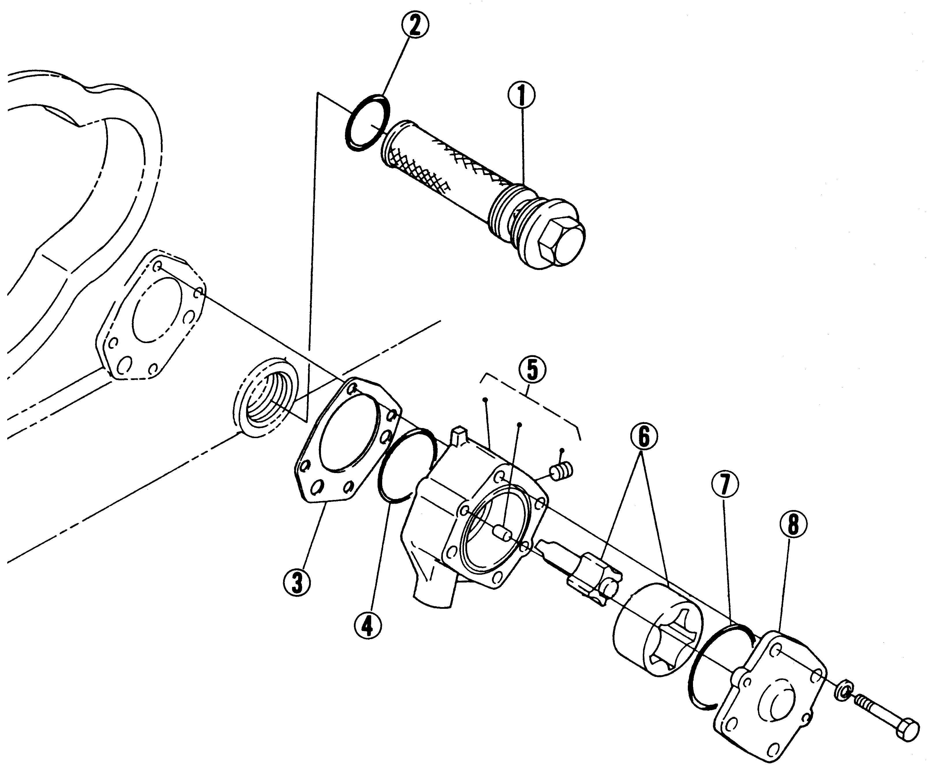
(1) Oil Filter
(2) O’ring
(3) Oil Pump Gasket
(4) O’ring
(5) Oil Pump Body
(6) Oil Pump Rotor
(7) O’ring
(8) Oil Pump Cover
(1) Filtro de aceite
(2) O’Ring
(3) Junta bomba de aceite
(4) O’ring
(5) Cuerpo de la bomba de aceite
(6) Rotor de la bomba de aceite
(7) O’ring
(8) Cubierta de la bomba de aceite
Oil Filter
1. Remove the oil filter
(When reassembling)
• Install the oil filter, noting O’ring (Hs70, P38).
Filtro de aceite
1. Sacar el filtro de aceite.
(Cuando se re-arma)
• Instalar el filtro de aceite, cuidando el O’Ring (Hs70, P38).
Oil Pump
1. Remove the oil pump assembly
2. Remove the oil pump cover to pull out the rotor
(When reassembling)
• Align the alignment marks on the inner rotor and outer rotor
• Apply the engine oil to the oil pump parts.
Bomba de aceite
1. Remover el conjunto de la bomba de aceite.
2. Remover la cubierta de la bomba de aceite para sacar el rotor
(Cuando se re-arma)
• Alinear las marcas de alineación del rotor interno a las del rotor externo.
• Aplicar aceite de máquina a las partes de la bomba de aceite.
SERVICING / MANTENIMIENTO
Clearance butween Inner Rotor and Outer Rotor
1. Use a feeler gauge to measure the inner rotortoouter rotor clearance between a high point on the inner rotor, and high point on the outer rotor
If the clearance exceeds the allowable limit, replace the inner and outer rotor assembly
Luz entre el rotor interno y el externo
1. Usar un medidor para medir la luz del rotor interno al externo entre un punto elevado sobre el rotor interno, y un punto elevado sobre el rotor externo.
Si la luz excede el límite permitido, cambiar el conjunto de rotor interno y externo.
Valor de referencia
Límite permitido
Clearance between Outer Rotor and Pump Body
1. Measure the clearance between the outer rotor and pump body with a feeler gauge.
If the clearance exceeds the aflowable limit, replace pump body or oil pump rotor (inner, outer).
Luz entre el rotor externo y el cuerpo de la bomba
1. Medir la luz entre el rotor externo y el cuerpo de la bomba con un medidor
Si la luz excede el límite permitido, cambiar el cuerpo de la bomba o el rotor de la bomba de aceite (interno, externo).
If the clearance exceeds the allowable limit, replace the oil pump rotor
Luz entre el rotor y la cubierta
1. Poner un medidor de presión en el rotor.
2. Instalar la cubierta y apretar el bulón.
3. Remover la cubierta cuidadosamente, y medir la depresión de la válvula de medición con una hoja de válvula.
Si la luz excede el límite permitido, cambiar el rotor de la bomba de aceite.
FUEL SYSTEM / SISTEMA DE COMBUSTIBLE [1] INJECYTION PUMP / BOMBA INYECTORA CHECKING AND ADJUSTING / CONTROL Y AJUSTE
Adjusting Injection Timing
1. Connect the injection pipe to the injection pump as shown in the photo.
2. Set the speed control lever to the maximum speed position.
3. Rotate the flywheel clockwise to check that fuel comes out from the tip of the injection pipe.
4. Rotate the flywheel so that the F I mark on the flywheel circumference reaches near below the casting mark “V” on the hopper. Slowly rotate the flywheel counterclockwise from that position, and stop it immediately when the fuel level at the tip of the injection pipe begins rising. At this time, check that the F I mark on the flywheel circumference aligns with the hopper's casting mark. “V”.
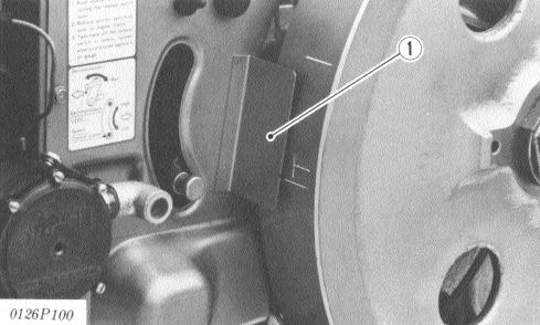
5. If the timing is incorrect, adjust it with shims.
6. After adjustment, apply liquid gasket to the both sides of the shim thinly before reassembling.
Ajustando el tiempo de inyección
1. Conectar el conducto de inyección a la bomba de inyección, como se muestra en la foto.
2. Colocar la palanca de control de velocidad a la posición de máxima velocidad.
3. Rotar el volante en el sentido de las agujas del reloj, para comprobar que el combustible sale por la punta del conducto de inyección.
(Reference)
• Reducing one shim 0.15 mm (0.0059 in.) advances the crank angle by approx. 0.026 rad., 1.5˚. Increasing one shim 0.15 mm (0.0059 in.) delays the crank angle by approx. 0.026 rad., 1.5°.
4. Rotar el volante de modo tal que la marca FI sobre la circunferencia del mismo se acerca por debajo de la marca “V” que está sobre el tanque de agua. Lentamente girar el volante en el sentido de las agujas del reloj desde esa posición, y detenerse inmediatamente cuando el nivel de combustible en la punta del conducto de inyección, comienza a aumentar. En este momento, controlar que la marca FI sobre la circunferencia del volante se alinea con la marca “V” grabada sobre el tanque de agua.
5. Si los tiempos son incorrectos, ajustarlos con calces.
6. Después del ajuste, aplicar una capa delgada de líquido de junta a ambos lados del calce antes del re-armado.
(Referencia)
• Al reducir un calce de 0.15 mm (0.0059 pulgadas), avanza el ángulo de la manija en aproximadamente 0.026 rad., 1.5˚. Al aumentar un calce 0.15 mm (0.0059 pulgadas), demora el ángulo de la manija
0.026 rad., 1.5˚.
Pump Element Fuel Tightness
1. Install the injection pump pressure tester (for 700 kgf/cm2) to the injection pump. (For the injection pump pressure tester, see page S-52).
2. Set the speed control lever to the maximum speed position.
3. Turn the engine ten times or more with the start handle to increase the pressure up to 39 MPa (400 kgf/cm2, 5689 Pa). (Use the decompress.)
4. Measure the time requ ired for the pressure to drop from 39 MPa (400 kgf/cm2, 5689 Pa) to 34 MPa (350 Kgf/cm2, 4978 psi). If the measurement is less than the allowable limit or the pressure does not reach 39 MPa (400 kgf/cm2, 5689 Pa), replace the pump element or injection pump.
Densidad del combustible del elemento bombante
1. Instalar el probador de la presión de la bomba inyectora (para 700 kgf/cm2) a la bomba inyectora. (Para el probador de presión de bomba inyectora, ver página S-52).
2. Colocar la manija de control de velocidad en la posición de máxima velocidad.
3. Girar el motor diez veces o más con la manija de arranque para aumentar la presión a 39 Mpa (400 kgf/cm2, 5689 Pa). (Usar el descompresor).
4. Medir el tiempo requerido para que la presión baje de 39 Mpa (400 kgf/cm2, 5689 Pa) a 34 Mpa (350 Kgf/cm2, 4978 psi). Si la medida es menor que el límite permitido o la presión no llega a 39 MPa (400 kgf/cm2, 5689 Pa), cambiar el elemento bombante o la bomba inyectora.
Delivery Valve Fuel Tightness
1. Set the injection pump pressure tester (for 29 MPa, 300 kgf/cm2 ,4300 psi) to the injection pump.
2. In the same way as to check the pump element fuel tightness, turn the engine ten times or more with the start handle so that the pressure is increased to 18.6 MPa (220 kgf/cm2, 2700 psi).
3. Position the plunger at the bottom dead center to reduce the delivery chamber pressure to zero. (To set the plunger at the bottom dead center, return the FI mark on the flywheel circumference 90° clockwise from the hopper's casting mark “s”.)
4. Measure the time required for the pressure to drop from the initial 21.6 MPa (220 kgf/cm2, 3129 psi) to 20.6 MPa (210 kgf/cm2, 2987 psi).
If the measurement is less than the allowable limit, replace the delivery valve or injection pump.
0104P106 Reference 21.6 Mpa Ô 20.6 220 kgf/cm2 Ô 210 kgf/cm2 3129 psi Ô 2987 psi 10 seconds or more valve value Allowable limit
Densidad del combustible de la válvula de envío
1. Colocar el tester para la presión de la bomba inyectora (para 29 MPa, 300 kgf/cm2 ,4300 psi) a la bomba inyectora.
2. En la misma forma como para controlar la densidad del combustible del elemento bombante, girar el motor diez veces o más con la manija de arranque de modo que la presión se incrementa a 18.6 Mpa (220 kgf/cm2, 2700 psi).
3. Posicionar el vástago en el centro muerto inferior, para reducir la presión de la cámara de envío a cero. (Para colocar el vástago en el centro muerto inferior, retornar la marca Fl sobre la circunferencia del volante 90º en el sentido de las agujas del reloj desde la marca fundida “s” del tanque de agua).
4. Medir el tiempo requerido para que la presión baje desde al inicial de 21.6 Mpa (220 kgf/cm2, 3129 psi) a 20.6 MPa (210 kgf/cm2, 2987 psi).
Densidad del combustible de la válvula de envío
Límite permitido
Disassembly And Assemble Desarmado Y Armado
Injection Pump
For removing the injection pump. (See page S-70).
n Important:
• Do not loosen the tappet guide screw at the injection pump control rack. (This causes improper fuel limiting, resulting in overrunning.)
1. Remove the delivery valve holder (1). Pull out the pump element (5), delivery valve (4), spring (3) and gasket (2).
2. Remove the clamp pin (13). Pull out the tappet (12), spring under seat (11), spring (10), spring upper seat (9), and control sleeve (8).
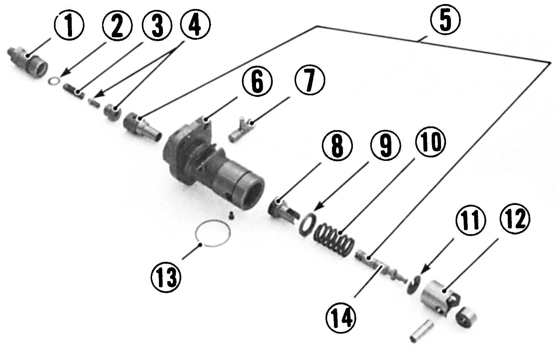
(1) Delivery Valve Holder
(2) Gasket
(3) Spring
(4) Delivery Valve
(5) Pump Element
(6) Pump Body
(7) Control Rack
(8) Control Sleeve
(9) Spring Upper Seat
(10) Spring
(11) Spring Under Seat
(12) Tappet
(13) Clamp Pin
(14) Plunger
(1) Soporte de la válvula de envío
(2) Junta
(3) Resorte
(4) Válvula de envío
(5) Elemento bombante
(6) Cuerpo de la bomba
(7) Cremallera de control
(8) Manga de control
(9) Asiento superior del resorte
(10) Resorte
(11) Asiento inferior del resorte
(12) Botador
(13) Grampa
(14) Vástago
(When reassembling) n Important:
• Install the plunger, correctly aligning the alignment marks on the plunger (14) and the control sleeve.
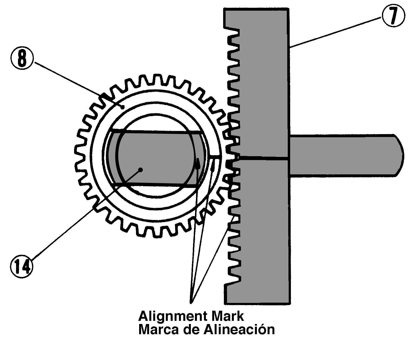
• Install the control sleeve, correctly aligning the alignment marks on the control sleeve and rack as shown in figure.
Bomba inyectora n Importante:
Para remover la bomba inyectora. (Ver página S-70).
• No aflojar el tornillo de la guía del botador en la cremallera de control de la bomba de inyección. (Esto causa una limitación inapropiada de combustible, resultando en sobre funcionamiento).
1. Remover el soporte de la válvula de envío (1). Empujar hacia fuera el elemento bombante (5), la válvula de envío (4), resorte (3) y la junta (2).
2. Remover el gancho de la grampa (13). Empujar el botador hacia afuera (12), asiento inferior del resorte (11), resorte (10), asiento inferior del resorte (9), y la manga de control (8).
(Cuando se re-arma) n Importante:
• Instalar el vástago, alineando correctamente las marcas de alineación sobre el vástago (14) y la manga de control.
• Instalar la manga de control, alineando correctamente las marcas de alineación sobre la manga de control y la cremallera como se muestra en la figura.
[2] INJECYTION NOZZLE TOBERA DE INYECCIÓN CAUTION
• Check the nozzle after confirming that there is nobody standing in the direction the fume goes. If the fume from the nozzle directly contacts the human body, cells may be destroyed and blood poisoning may be caused.
• Controlar la tobera después de confirmar que no hay nadie en la dirección en que salen los gases. Si los gases de la tobera tocan directamente el cuerpo humano, las células pueden ser destruidas y se puede producir envenenamiento de la sangre.
Fuel Injection Pressure
1. Set the injection nozzle to the nozzle tester (Code No.: 07909-31361).
2. Slowly move the tester handle to measure the pressure at which fuel begins jetting out from the nozzle. If the measurement is not within the reference values, remove the mounting. nut of the nozzle holder and adjust with the adjusting screw
(Reference)
• Pressure change per 1/4 turn of adjusting screw Approx. 6.08 MPa (62 kgf/cm2, 882 psi).
Presión de la inyección de combustible
1. Colocar la tobera de inyección al probador de tobera (Código Nº 07909-31361).
2. Mover la manija del probador lentamente para medir la presión a la cual el combustible comienza a dispararse desde la tobera.
Si la medida no está dentro de los valores de referencia, remover la tuerca de montaje del soporte de tobera y ajustar con el tornillo de ajuste.
(Referencia)
• La presión cambia cada 1/4 de giro del tornillo de ajuste. Aproximadamente 6.08 Mpa (62 kgf/cm2, 882 psi).
0104F043
Nozzle Spraying Condition
1. Check the nozzle spraying condition.
2. If the spraying direction and pattern are different from those shown in the figure, replace the nozzle piece.
Estado del aerosol de la tobera
1. Controlar el estado del aerosol de la tobera.
2. Si el estado del aerosol y el patrón son diferentes de los mostrados en la figura, cambiar la pieza de la tobera.
Fuel Tightness of Nozzle Needle Valve Seat
1. Set the nozzle to the nozzle tester, and adjust the pressure to 17.7 MPa (180 kgf/cm2, 2560 psi). The valve seat is normal if fuel will not leak from the nozzle 10 seconds after
Fuel tightness of nozzle needle valve seat
Reference value No fuel shall leak at 17.7 MPa (180 kgf/cm2, 2560 psi)
Densidad del combustible de la aguja del asiento de válvula de la tobera
1. Colocar la tobera en el tester para tobera, y ajustar la presión a 17.7 MPa (180 kgf/cm2, 2560 psi). El asiento de válvula está normal si la tobera no pierde combustible 10 segundos más tarde.
Densidad del combustible de la aguja del asiento de la válvula de la tobera
Valor de referencia No habrá pérdida de aceite a 17.7 MPa (180 kgf/cm2, 2560 psi)
0104P005
Disassembly And Assemble Desarmado Y Armado
Nozzle Piece n Important:
1. Secure the nozzle holder body with a vise, and remove the nozzle holder (1) and cap nut (10).
2. Take out parts in clean light oil.
3. Check the surfaces of the nozzle piece for flaw.
• Since the nozzle piece is precision finished, wood piece must be used to remove carbon deposit. Do not use metal pieces.
4. After removing carbon, clean the nozzle piece in light oil. Insert the needle valve into the nozzle body from the top and check that it drops smoothly
If the valve stops midway, replace the nozzle piece.
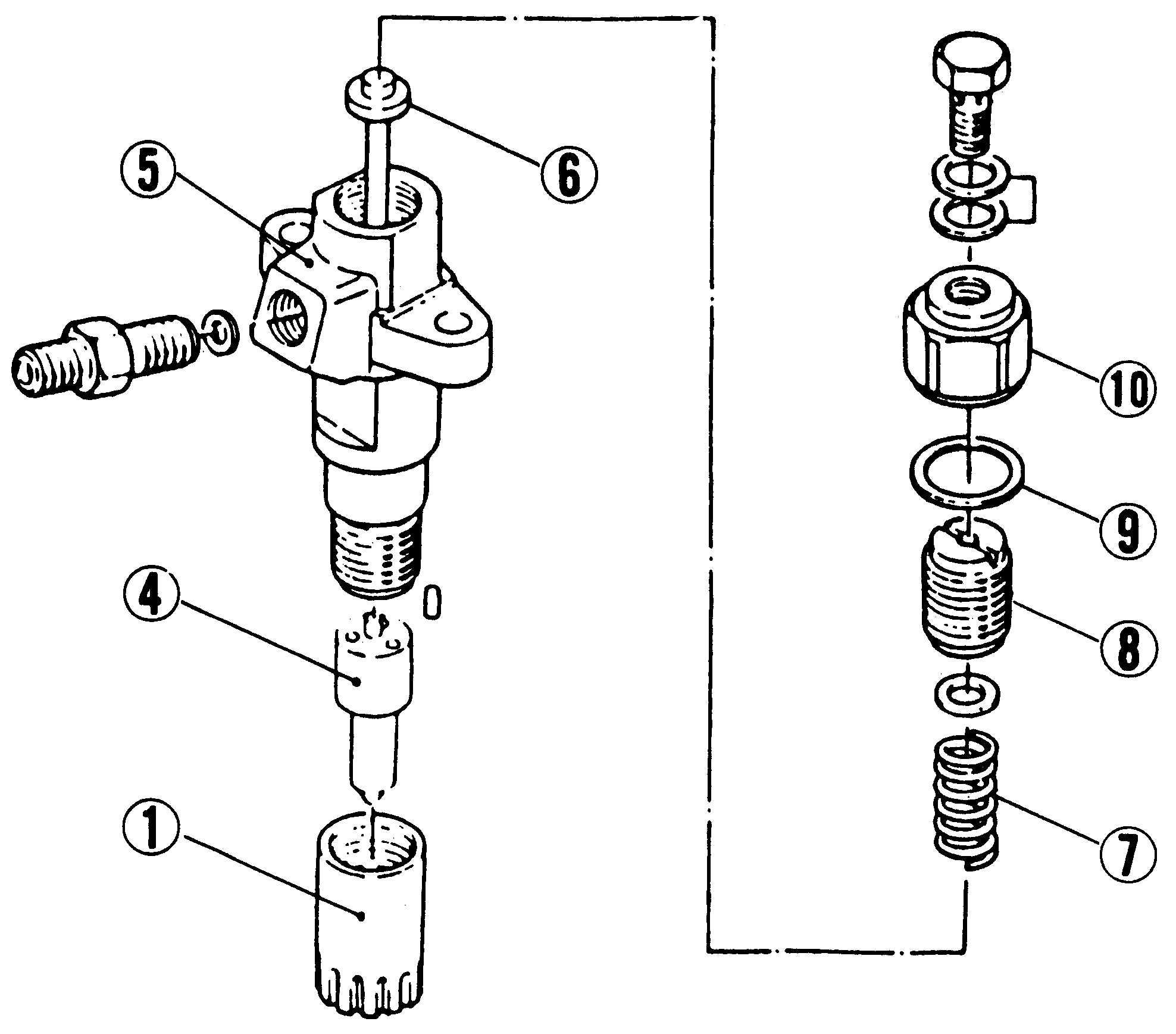
(1) Nozzle Holder
(2) Nozzle Body
(3) Needle Valve
(4) Nozzle Piece
(5) Nozzle Holder Body
(6) Push Rod
(7) Spring
(8) Adjusting Screw
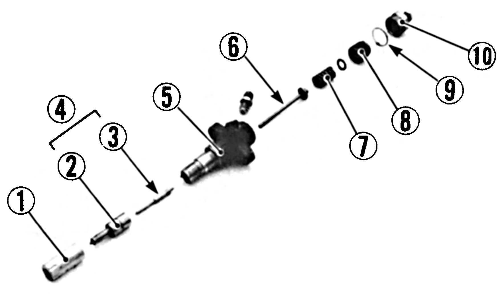
(9) Gasket
(10) Cap Nut
C057P058 0104F091
1) Soporte de tobera
2) Cuerpo de la tobera
3) Aguja de válvula
4) Parte de la tobera
5) Soporte del cuerpo de la tobera
6) Varilla de empuje
7) Resorte
8) Tornillo de ajuste
9) Junta
10) Tuerca de la tapa
(When reassembling) n Note: n Important:
• Assemble the nozzle in clean light oil.
• Install the push rod, noting its mounting direction.
• After assembly, adjust the fuel injection pressure. (See page S-120).
Parte de tobera n IMPORTANTE
1. Asegurar el cuerpo del soporte de la tobera con una prensa, y remover el soporte de tobera (1) y la tuerca de la tapa (10).
2. Sacar las partes en aceite liviano.
3. Controlar las superficies de la parte de tobera por hendiduras o imperfecciones.
• Dado que la parte de tobera está terminada con precisión, la parte de madera debe ser usada para remover el depósito de carbón.
4. Luego de remover el carbón, limpiar la parte de tobera en aceite liviano. Insertar la aguja de la válvula dentro del cuerpo de la tobera desde la parte superior y controlar que este caiga suavemente. Si la válvula se detiene a mitad de camino, cambiar la parte de tobera.
(Cuando se re-arma) n NOTA: n IMPORTANTE:
• Ensamblar la tobera en aceite limpio y liviano.
• Instalar la varilla de empuje, vigilando su dirección de montaje.
• Después del ensamblaje, ajustar la presión del combustible de inyección. (Ver página S-120).


