15 minute read
Messages / Warnings

Information Screens
The JCB Digital Control Panel can be used to display information about the status of the engine, alternator and complete generation system. Depending on the application the JCB Digital Control Panel has a varying number of information ‘screens’. To access these screens use the scroll button as follows.
NOTE
While scrolling Information screens user can scroll up (to access previous screen) as well as down (Accessing the next screen). Additional features are accessible in some of the screens, indicated by icons beside the soft keys.
Top Level Screen
¾
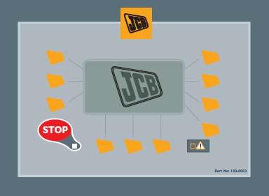
The sub menu, information screens are accessed through scrolling from the top level screen. Top level screen provides an overview of the generating set and is the starting point for accessing other information screens.
Mains Overview Screen (only when enabled)
¾
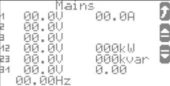
This screen provides the mains voltage information; user can change the method of voltage measurement for the mains reading see
‘Changing method of voltage calculations’, also displayed are mains frequency, kW and phase current. ½
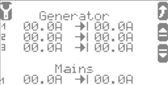
Generating Set Overview Screen
¾
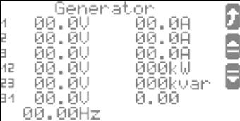
All parameters monitored from the Genset are displayed here.
Generator voltages line-line and line-neutral; generator currents for each phase; generator frequency; generator real/reactive power, power factor and engine RPM.
½ ) Return to ‘Top Level’
Mains Values Details
All mains parameters measured are displayed on this screen. Mains voltages line-line and line-neutral; Mains current; Mains frequency; Mains real/reactive power and power factor.
¾
Generator Peak Currents
½
Return to ‘Top Level’
Displays the peak (maximum), generator and mains currents per phase.
¾ )
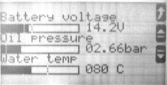
Analogue Inputs
½ )
Return to ‘Top Level’ Configure
This screen displays the information from the analogue inputs. Feedback is provided about the status of battery voltage, oil pressure and coolant temp.
¾ ½
Digital Inputs and Outputs Return to ‘Top Level’
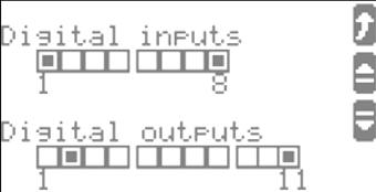
Information is provided about the digital inputs and outputs. An input / output is set if the corresponding block is seen as shaded.
¾ ½
Return to ‘Top Level’
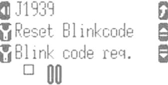
J1939 & Blink Screen (only available on selected models)
¾ )
Real Time Clock

Allows for access to Engine Information through the J1939 data link (see acquiring Engine information). Also allows for service level access to Blink code configuration, not a user accessible feature.
½ )
Return to ‘Top Level’ )
Configure
Displays time and date information.
¾
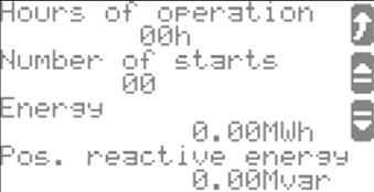
Counters
½
Return to ‘Top Level’
Displays the total hours run for the machine, the number of successful starts during this time and total generator real / reactive energy produced.
¾
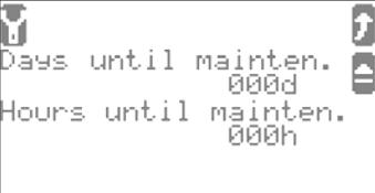
Maintenance Call
½
Return to ‘Top Level’
Displays the days and running hours remaining until a maintenance call will be activated. Configuration only accessible with commissioning password.
½
Return to ‘Top Level’ Configure
Main Menu
The Main menu provides access to the factory set parameters that can be configured by the user. To access the basic main menu from the top level screen, press soft key
Access Main Menu
Basic Main Menu
The basic main menu is the entry level menu, accessible by all users and requires no password. Use the scroll up and down soft keys to highlight different items in the menu list, a highlighted item will appear as follows;

To enter a highlighted items submenu use the exit the current menu.
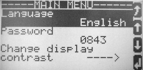
Basic Main Menu List
key; while use of the key will

Allows for changing the unit language, press to enter, and then use the soft key to scroll through the available options, using to accept a change and soft key to exit to the previous menu (main menu).

This option is for factory use to configure system parameters/defaults and also for commissioning/service.

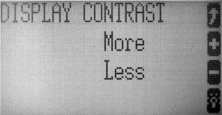
This option allows for changing the contrast of the LCD display on the JCB Digital Control Panel. Press soft key to enter, to increase or decrease contrast press or accordingly. If the contrast has been set too low that the screen is not visible push the STOP button for at least five seconds and contrast will be reset to standard value. Pressing at any time will exit the contrast menu without making changes.

The configure monitoring menu, enables the user to make changes to ‘time until horn reset’ parameter. This setting determines how long the horn will sound after an alarm has been raised before automatically resetting (Default 180s).
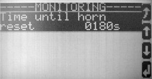
To make changes enter configure monitoring screen, and then enter the ‘time until horn reset’ parameter. To adjust the value use the right arrow key to scroll between digits (thousands – hundreds – tens – units), while using the up key to scroll values 0-9 for each of the digits. When finished pressing enter key will save any changes, while exit key will exit to the previous menu without changes.

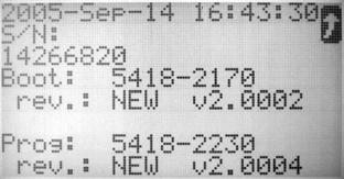
The system parameter submenu contains information on the password system, clock set and version. The ‘password system’ is a factory adjusted parameter and is not of use to the user. To change the clock settings refer to section ‘setting the clock’ while the ‘Version’ menu when entered displays manufacturing information on the JCB Digital Control Panel panel, including serial number and Firmware version.
Setting the Clock
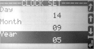
The real-time clock on the JCB Digital Control Panel is factory set to GMT, however adjustment of the clock values (Hour-Second-Minute-Day-Month-Year) can be made by following the steps.
Access Main Menu
(from the ‘Top Level’ screen)
Scroll Down to Highlight ‘System Parameter’
Enter the System Parameter Menu
Scroll Down to Highlight ‘Clock Set’ and Enter )
Scroll to and Enter Value Requiring Change
(repeatedly)
OR ) THEN )
To Highlight Specific Digits
Accept Changes Made
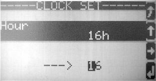
To Scroll 0-9 for that Digit
Exit without Making Changes )
Acquiring Engine Information
If the Genset has an electronic engine control unit (ECM) with J1939 communication enabled, then it is possible for the user to browse information from the Engine. This information is extremely useful in diagnosis of any engine issues or faults. To enter the J1939 (Scania Engine example) menu scroll from the top level, screen through the information screens. Then to enter the J1939 Information list push the soft key (corresponding to the J1939 text)
Enter J1939 List )

The J1939 Messages can be browsed by using the UP and DOWN arrows, and the list exited at any time by utilizing the return to previous menu key . Depending on the application the J1939 parameter list provides a host of information from the engine control unit (ECU), this can include, oil temperatures, pressures, fuel rate and various other engine parameters.
Scania Specific Fault Codes
For Generating sets utilising the Scania electronic engine the user can request blinkcodes (for engine diagnostics) and reset them. To request a blinkcode while viewing the above screen press the ‘Blink code req’ - soft key, repeated pressing will scroll through all logged & active fault codes. While viewing blinkcodes they can be cleared by pressing the ‘Reset Blinkcode’ soft key causing the code to be reset as long as the fault is not active.
Appendix 1 Possible Alarms
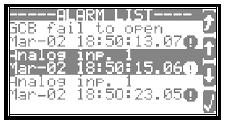
This appendix lists all the possible alarms displayed in the JCB Digital Control Panel ‘Alarm List’ screen
Overspeed 1
Overspeed 1 Indicates that the engine has experienced / is currently in an overspeed condition (above the first overspeed set limit).
Over Speed 2
Overspeed 2 Indicates that the engine has overspeed past the second overspeed limit value, this error will cause generating set shutdown.
Underspeed 1
Underspeed 1 indicates that the engine has experienced an underspeed condition (fallen below speed limit 1).
Underspeed 2
Underspeed 2 indicates that the engine speed has fallen below the second threshold point, and will cause shutdown of the generating set.
Gen. Underfreq.1
Under frequency Indicates that the generated frequency has gone below the minimum allowed value typically 90% of rated frequency. Can be a result of overloading the generating set.
Gen. Overfreq.1
Over frequency indicates that the generated frequency has gone beyond the maximum allowed value typically 110% of rated frequency.
Oil.Temp.1
Oil Temperature Level 1 warning Indicates that engine oil temperature of the generating set has reached an abnormally high value.
Oil.Temp.2
Indicates that the Oil Temperature has increased beyond threshold level 2 and will cause generating set shutdown.
Water.Temp.1
Water Temperature Level 1 Warning indicates that the engine coolant temperature has reached an abnormally high value.
Water.Temp.2
Water Temperature Level 2 warning indicates that the coolant temperature has increased beyond the second limit point, and will cause a generating set shutdown.
Water Temp Sw
Water Temperature Switch indicates that the coolant temperature has been/is abnormally high.
Stop Pressed
Stop Pressed / Emergency Stop Indicates that the machine has been manually shutdown by use of the STOP switch on the panel, or other external emergency stop buttons (warning must be acknowledged before restart can take place).
Unintended Stop
Unintended Stop indicates that the JCB Digital Control Panel is expecting to see generated frequency and voltage but none is present. This can happen for example if the engine runs out of fuel and stops without Control panel commanding it to stop.
Batt.Undervolt.1
Battery Undervoltage alerts the user to the fact that the generating set-starting battery voltage is below the expected level. This can indicate that the charging alternator / static battery charger are not functioning correctly /have been disconnected. Could also be activated if the system is 24V but has been incorrectly connected to a 12V battery.
Batt.Undervolt.2
Indicates that the battery voltage has fallen below a second threshold point
Batt.Overvolt.1
Battery Over Voltage alerts the user to the fact that the generating set-starting battery voltage is above that expected by the Control panel. This can point towards a fault in the static battery charger or charging alternator. Could also indicate that a 12V system has been incorrectly connected to a 24V battery.
Batt.Overvolt.2
Indicates that the battery voltage has increased beyond the second threshold point.
CAN-Fault J1939
CAN Fault J1939 Indicates that connection to the Engine CAN Bus has failed and no data can be transmitted over the bus. This could be cause by incorrect, faulty or loose CAN wiring.
Shutdown Malfct
Shutdown Malfunction indicates that the engine has failed to shutdown when commanded. When stop is pressed the JCB Digital Control Panel intelligently monitors the engine to see if the STOP command has been fulfilled. Most common cause would be incorrect / faulty wiring to the fuel solenoid.
Mainten. Days Exceeded
Maintenance Days Exceeded, the generating set has exceeded the configured number of days since the last maintenance period.
Mainten. Hours Exceeded
Maintenance Hours Exceeded, the generating set run time has exceeded the configured number of days since the last maintenance period
GCB Fail to Close
Generating set Circuit Breaker fail to close, the JCB Digital Control Panel controller has attempted to close the Generator Circuit Breaker the configured number of times, and the attempts have failed. Depending on the system configuration the JCB Digital Control Panel will continue to try and close the GCB while the conditions are fulfilled.
GCB Fail to Open
The JCB Digital Control Panel is still seeing the GCB closed signal after it has commanded it to open, and after the configured period of time.
MCB Fail to Close
The JCB Digital Control Panel has attempted to close the Main circuit breaker the configured number of times, depending on the system configuration the Control panel will continue to attempt closing of the MCB as long as the conditions are right.
MCB Fail to Open
The JCB Digital Control Panel is still receiving the MCB closed signal after it has commanded it open and the monitoring time has expired.
Emergency Stop
Either the Canopy (if fitted) or the panel mounted emergency stop switch has been pressed. In order to reset the ESTOP button must be released and the alarm acknowledged before restarting is possible.
Appendix 2 Status Messages
This appendix contains the list of status messages that the JCB control panel can flag up to indicate various conditions.
Preglow
Indicates that the Diesel engine is heating in preparation for starting.
Start
Indicates that the engine start sequence is active, appears after any prerun auxiliary operation (preglow). JCB Digital Control Panel activates the start relay and/or CAN message is sent to engine to demand starting.
Start Pause
If the engine does not start after cranking, ‘Start Pause’ is displayed during which time the controller will pause for a period before attempting another start. If the engine fails to start after three attempts then the routine stops and the Control panel displays alarm ‘Fail to Start.
Crank Protect
This message is displayed if the engine is running or has just been stopped and the START button is pressed. The JCB Digital Control Panel protects the starter by stopping its operation if the engine is rotating (can be stopped and still turning or actually running).
Cool Down
The JCB Digital Control Panel allows the engine to run for a predetermined period after a stop signal has been received, to promote engine cool down before it mechanically stops. Cool down is not entered if emergency stop is pressed or if STOP soft key is pressed twice (immediate stop requested).
Stop Engine
Engine will be stopped, a restart will not be allowed (crank protect) until controller observes the absence of speed and frequency for a period of time.
GCB Dead Bus Close
The Generator Circuit Breaker is closed unto a de-energised busbar. This is activated by either the absence of a MCB or by reply ‘MCB is open’. During commission ensure that no other sources are energizing the busbar, if this information is unknown check busbar status by another means.
MCB Dead Bus Close
The Mains Circuit Breaker is closed unto a de-energised busbar, actuated by the JCB Digital Control Panel receiving GCB is open signal. During commissioning ensure that the busbar is de-energised, if unknown check busbar status using another means.
Emergency Run
The JCB Digital Control Panel detects that a mains fault has occurred and starts the engine after a pre determined delay period. The MCB is opened and GCB closed, the generating set accepts the load. When mains power returns, The JCB control panel goes into ‘Mains settling’ mode
Mains Settling
In Emergency Run when the JCB Digital Control Panel determines that the Mains power has returned, it monitors the Mains for a pre determined time to ensure that the mains is stable, before opening the GCB, closing the MCB and passing the load back to the mains.
Index
A Accept Changes ........................................17
Access Alarms
...........................................10 Access Main Menu ....................................15 Access Mains Overview Screen ................11 Acknowledge an Alarm ..............................10 Acquiring Engine Information ....................18 Alarm List...................................................10 Alarms........................................................19 Analogue Inputs.........................................13 Application Modes .......................................6 ATP7 Operation...........................................6 Automatic Mode...........................................9 B Basic Main Menu .......................................15 Battery Over Voltage .................................20 Battery Undervoltage.................................20 C CAN ...........................................................20 Change 3 Phase Voltage Calculations ......11 Changing Method of Voltage Calculations 11 Circuit Breaker Closed .................................8 Circuit Breaker Open ...................................8 Circuit Breaker Status..................................8 Cool Down .................................................22 Coolant temperature..................................19 Counters ....................................................14 Crank ...........................................................7 Crank Protect.............................................22 crank symbol................................................7 Current Mode of Operation..........................5 D Dead Bus Close.........................................22 Digital Inputs and Outputs ...................13, 14 E Emergency Run.........................................22 Emergency Stop ..................................20, 21 Emergency stop button................................7 Engine Information.....................................18 Engine Status ..............................................5 Enter AUTO Mode .......................................9 G GCB open/Closed....................................... 8 Generated Output Power............................ 5 Generator Circuit Breaker......................... 21 Generator Circuit Breaker Status ( ............. 5 Generator Overview Screen ..................... 12 Generator Peak Currents.......................... 13 Generator Voltage....................................... 5 H Highlight Specific Digits ............................ 17
I Immediate Stopping
.................................... 7 Information Screens.................................. 12 J J1939 ........................................................ 18 J1939 parameter....................................... 18 M Main circuit breaker................................... 21 Main Menu ................................................ 15 Main Menu List.......................................... 15 Mains Overview Screen............................ 12 Mains Settling ........................................... 22 Mains Values Details ................................ 13 Mains/utility supply Circuit Breaker Status . 5 Maintenance Call ...................................... 14 Maintenance Hours Exceeded.................. 21 Manual ATP7 Operation ............................. 8 Manual Start ............................................ 7, 8 Manual starting ........................................... 7 Manual Starting and Stopping .................... 7 Manual stopping.......................................... 7 MCB open/Closed....................................... 8 Messages / Warnings ................................. 5 N Navigate Up Or Down Through Alarm List 10 Normal Stopping ......................................... 7
O Oil Temperature........................................ 19 Over frequency ......................................... 19 Overspeed ................................................ 19 P Phase Current Monitoring........................... 5 Preglow ..................................................... 21
R Real Time Clock ........................................14 Reset an Acknowledged Alarm .................10 Return to ‘Top Level Screen ......................10
S Scroll
..........................................................17 Setting the Clock........................................17 Shutdown Malfunction ...............................20 soft key ........................................................4 Standard operation ......................................6 Start - .........................................................21 Start Pause................................................22 Status Messages .......................................21 Stop button.................................................. 4 Stop Engine .............................................. 22 STOP LED .................................................. 5 Stop Pressed ............................................ 20 System Frequency...................................... 5 T Top Level screen ........................................ 3 Top Level Screen.................................. 5, 12 U Under frequency ....................................... 19 Underspeed .............................................. 19 Unintended Stop ....................................... 20 W Water Temperature................................... 19