2 minute read
SERVICE MANUAL FOR TC213F


II.BRAKE COMPONENTS
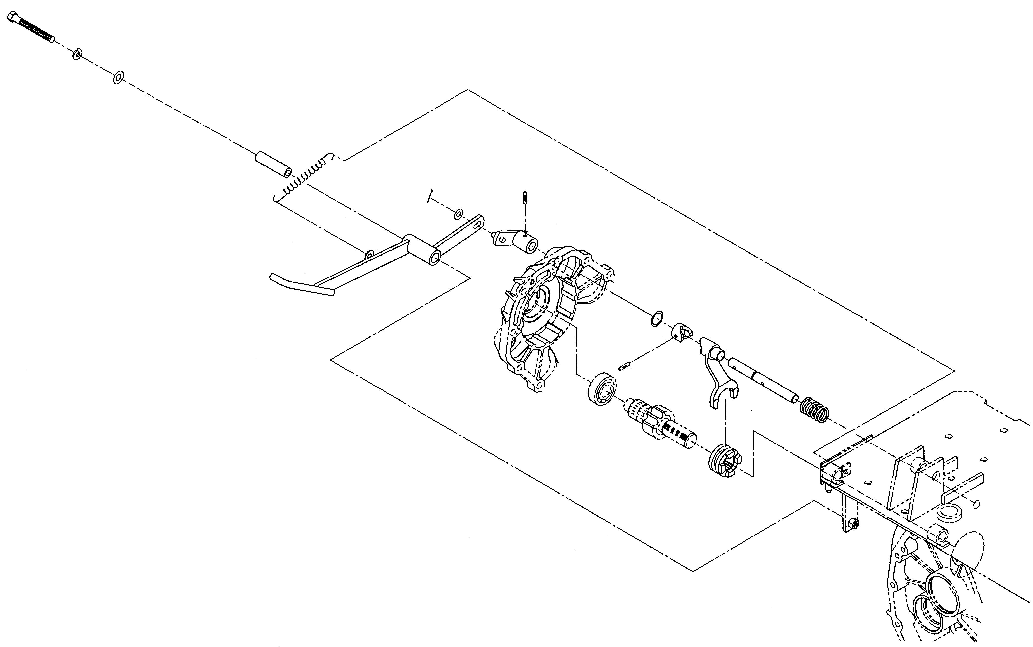
III.DIF-LOCK LINKAGE COMPONENTS
CHAPTER 5. HYDROSTATIC TRANSMISSION
II.REAR AXLE HOUSING AND DIFFERENTIAL GEARS
1.DISASSEMBLY
1.1.REAR AXLE HOUSING
a.Drain the transmission oil.
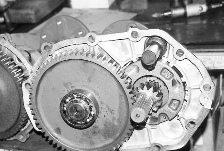
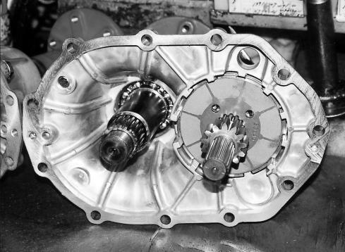
b.Remove the rear transmission cover.
1.2.DIFFERENTIAL GEARS
d.Remove the right and left dif-case metal. Note: e.Remove the differential assembly. f.Remove the bearings from both sides of the differential assembly. g.The differential assembly can be disassembled by removing the dif-pinion shaft.
When the dif-case metal is fitted too tightly in the rear transmission case to be removed manually, use push bolts. The push bolts should be screwed in evenly and gradually.
Note:
The lock pin should be removed ahead of time.
2.INSPECTION
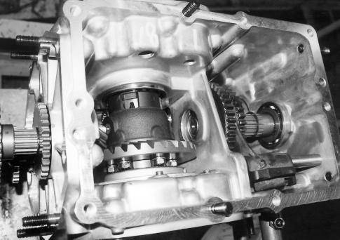
a.Check each gear and shaft for damage, tooth bearing, etc.
b.Check the bevel pinion for the differential and pinion thrust collar for wear.
c.Check to see that each bearing turns smoothly without hitching.
d.Make sure that the oil seal lips and lip contact surfaces on shafts have no flaws.
3.PRECAUTIONS FOR RE-ASSEMBLY AND ADJUSTMENT
a.Backlash adjustment between the drive pinion and ring gear i.As drive pinion and ring gear make a pair, take care not to interchange either of them with one of the other pairs. ii.Adjust the backlash to be 0.1 to 0.2 mm by shimming
Standard shimming thickness0.4 mm iii.After adjustment, tap the outer circumference with a copper hammer and make sure that the backlash does not change. Check backlash at four points 90 degrees apart from each other. b.After reassembling, each gear and related part should move smoothly.
Tooth Bearings
Correct bearing
When the drive pinion and the ring gear are meshed correctly with each other, and their backlash is within the specified range (0.1 - 0.2 mm), the bearing trace is positioned at the middle of the ring gear tooth and is approximately three fourths of the total tooth width.
Face bearing
This indicates that the drive pinion and the ring gear are meshed too shallowly and their backlash is too great. This will result in rapid wearing of the tooth tops. This bearing must be repaired by shifting some the left dif-case metal shims to the left-hand side.
Flank bearing
This indicates too deep a meshing of the drive pinion and the ring gear and too small a backlash. This will cause stepped tooth wear. Repair this in the reverse way of repairing the face bearing.
Precautions For Disassembling And Reassembling Rear Axle
Grooved pin Shift arm
O-ring groove
Standard shimming: 0.4 mm for each side (0.2-mm shim: one piece; 0.1-mm shim: two pieces)
Rear transmission case
Rear axle sub-assembly Never fail to install the spring.
When installing or removing the grooved pin, move the shift arm so that the Oring groove receives no load. Install the gear in right direction.
Rear transmission case
Be sure to apply grease to the ball before installation. Differential case metal (support)
Take care not to allow the ball to fall.
Apply screw locking agent: Chemiseal L324. Tightening torque: 26.5 N m (270 kgf m)
Apply grease. Dimension A should be secured when gear meshing is tested. Each pinion bears respective allowance. Oil drain holes in brake discs should be aligned and brake discs and separator plates should be installed in right sequence.
Preset components: they have the same ID number.
Backlash: 0.1 –0.2 mm, which should be adjusted by shimming at dif-case metal (support).
Install the pressure plate bearing the letter R in relief.
Apply adhesive: Three Bond 1901. A
•Each sub-assembled gear should turn smoothly without hitching by hand.
•The brakes should work properly.
Number of standard shims: 0.2 mm: 1 piece;0.1 mm: 2 pieces
•Make sure that the dif-lock works (except for type S).
•Sub-assembled wheel shafts should turn smoothly.
Apply grease. Apply adhesive to the contact surfaces of axle housing and rear transmission case: Three Bond 1208E or Chemiseal 1000HM.
Never fail to install the snap ring. Apply grease.
Install the arm aligning the matching marks.
The dif-pinion should turn smoothly. Backlash: 0.1 to 0.2 mm Install the pressure plate bearing the letter L in relief.
Install the oil seal using a jig which is designed to bear load only on the hatched part. Apply grease.


