12 minute read
CHAPTER 2. ATTACHING AND DETACHING MOWER DECK

from Iseki Front Mower SF224 & SF235 Mower Decks SCMA54 SCMB60 SSM54 Collector SBC950 Operator's Manual

WARNING: When attaching or detaching the mower deck to the front mower:
・Place the front mower on level, hard ground.
・Apply the parking brake securely.
・Do not start the engine except for operating the mower lift lever.
1. ATTACHING THE MOWER DECK
Attach the mower deck first to the front mower and then connect the drive shaft.
■ INSTALLATION OF MOWER DECK
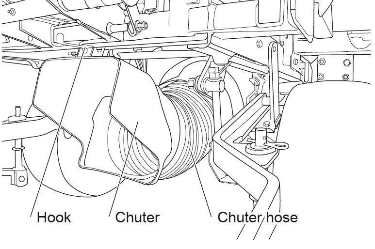
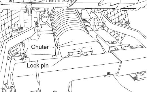
a. Start the engine and shift the mower lift lever to “UP” position to lift up the lift arm, then stop the engine. Insert the chuter hose into the blower hall, hook the chuter on lower frame.
b. Put the mower deck in front of the front mower, shift the mower lift lever to “DOWN” position, then lift down the lift arm.
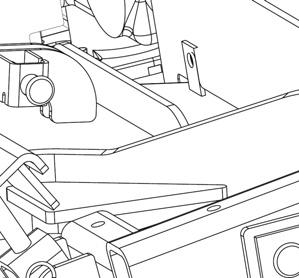
c. Assemble the right-hand and left-hand lift arms to the mower deck, with pin.
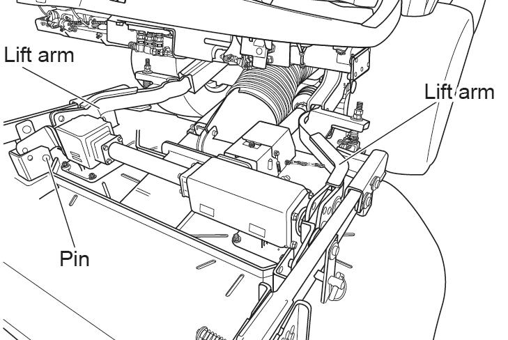
IMPORTANT: When it is difficult to align the hole in the lift bracket and the hole in the link ball, never attempt to insert the pin forcibly. But sway the mower deck right and left and the pin can be inserted easily.
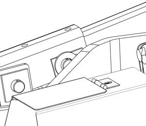
d. Attach the chuter on mower deck, fix it by lock pin.
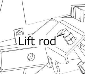
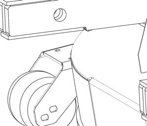
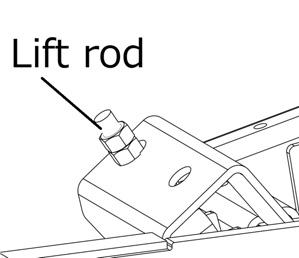
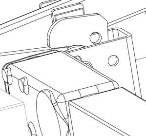
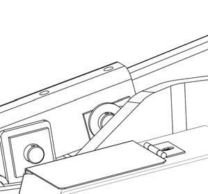
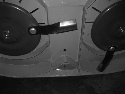
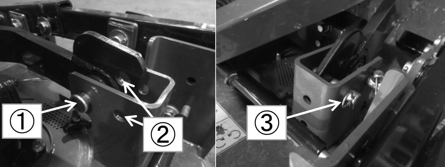
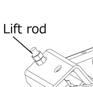
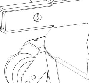
e. Start the engine and lift up the mower deck. Stop the engine and fix the fulcrum plate in the back of the mower deck to the folk under the lift rod by inserting pin and hair pin. Lower the mower deck onto the ground.
2. ADJUSTMENT OF LINKAGE
2.1. ADJUSTMENT OF MAXIMUM LIFTING HEIGHT
Be sure to adjust the lifting height of each side.
Max.height:A =575mm ± 10mm
4. DETACHING THE MOWER DECK
Detach the mower deck in reverse order of attaching: Remove the drive shaft first and then the mower deck.
CAUTION: Be sure to disconnect the universal joint on the PTO shaft of the front mower.
IMPORTANT: Be sure to keep the removed parts.
CAUTION: Incorrect adjustment may lead hitting between the step and gear box of mower deck or shortening of the minimum ground clearance.
3. ATTACHING THE UNIVERSAL JOINT
Hold the ring of the universal joint pressed in one side the joint onto the PTO shaft while aligning the splines. Fix the chain for universal joint to the linkage.
CHAPTER 3. MOWER OPERATION
1. BEFORE OPERATION
CAUTION :
・Become familiar with how to operate the front mower and understand safety instructions by reading this manual carefully.
・Make sure that all safety covers and guards are installed in position.
・Make sure that the blade bolts are tightened securely.
・Before moving the front mower into the working site, check the whole area and get rid of all obstacles such as stones, wood, empty tins, bottles, wires, etc to assure safe operation.
・Make sure that the mower operation will not cause any injury to children, animals, bystanders, or damage to trees, buildings, etc.
・Check the place to mow for bumps, ditches, mounds, steps, slopes, inclination, softness, water pools, etc. beforehand to avoid accidents such as turnover, fall, side-sliding of the front mower.
2-1. CUTTING HEIGHT ADJUSTMENT (SCMA54)
a. Depress the brake pedal and then start the engine.
b. Raise the mower with the lift by shifting the mower lift lever. Then stop the engine.
c. Remove the pin from the front gauge wheel. Remove the pin while holding the gauge wheel with the other hand.
d. Select one of the setting holes to get the required cutting height, insert the pin, and retain it with the pin. The label that is showing the relationships between the setting holes and cutting heights is stuck on the mower deck.
e. Also set the cutting height of the lift rod by resetting the setting hole for the setting pin with the spring clip removed.
f. The right and left-hand side of lift rods should be set to the same cutting height.
g. Shift the mower lift lever to the DOWN position to lower the mower deck.
CAUTION : Before operating the mower lift lever, be seated in the operator's seat and make sure of the safety conditions when lowering the mower deck.
a. Depress the brake pedal, and then start the engine.
b. Raise the mower with the lift. Then stop the engine.
c. Remove the pin from the front gauge wheel. Set the pin while holding the gauge wheel with the other hand.
d. Select one of the setting holes to get the required cutting height, insert the pin, and retain it with the spring clip. The label that is showing the relationships between the setting holes and cutting heights is stuck on the mower deck.
CHAPTER 3. MOWER OPERATION
f. The right and left gauge wheels should be set to the same cutting height.
g. Shift the mower lift lever to the DOWN position to lower the mower deck.
CAUTION : Before operating the mower lift lever, be seated in the operator’s seat and make sure of the safety conditions when lowering the mower deck.
e. Also set the cutting height of the rear gauge wheels by re-setting the setting hole for the setting pin with the ring clip removed.
3. STARTING MOWING OPERATION
CAUTION : a. Start the engine and turn the throttle lever (5) to the intermediate position between the low speed and high speed positions. b. Shift the mower lift lever (4) to the up position to raise the mower deck. c. Release the parking brake. d. Depress the HST forward travel pedal gradually to drive the front mower into the working site. e. Release the HST pedal gradually to stop the front mower. f. Shift the mower lift lever (4) to the down position to lower the mower on the ground. g. Select the MOWER AND BLOWER SWITCH from (A1) to (A3) for proper operation. h. Slide and push BOTTOM button(B2) of PTO ROTATION Switch.
・Read the contents of this manual thoroughly and carefully and keep safe operation in mind.
・Before moving the front mower into the working site, investigate the whole site and get rid of all obstacles such as stones, wood, empty tins, bottles, wires, etc for operation safety.
・Investigate the site for pits, mounds, steps, slope angles, ground softness, water pools, etc to avoid turning over, falling down, and side-shifting.
・Also make sure there is no danger of hurting children, animals, by-standers. and damaging nearby trees, buildings, etc.
NOTE: In order to operate blower PTO or mower PTO, PTO ROTATION SWITCH (PTO ON/OFF SWITCH) to be set ON position by sliding(B3) and push Top button(B1).
Push Top button of PTO ROTATION SWITCH, when stopping PTO operation.
A:MOWER AND BLOWER SWITCH
(1) Mower PTO switch (Forward/TOP)
(2) Blower PTO switch (Rearward/BOTTOM)
(3) For Mower and Blower (Center)
NOTE: When blower and mower PTO are operating, both blower and mower PTO will stop by pushing the blower PTO switch.
NOTE: When the collector is lifted, mower and blower PTO cannot be operated.
NOTE: When this switch is in center position, both mower and blower can be operated, if the PTO ON/OFF switch is in ON position.
(4) Mower lift lever (5) Throttle lever
B:PTO ROTATION Switch
(1) TOP button
(2) BOTTOM button
(3) Sliding Direction
*Please also refer to P38 1.5 MOWER AND BLOWER SWITCH section and 1.6 PTO ROTATION SWITCH.
CAUTION :
・PTO restriction mechanism works only while the PTO is working.
・Before starting to mow, make sure that this mechanism works properly. Be sure to detach the drive shaft before checking the PTO restriction mechanism.
・Be restricted from lift up the mower deck excessively while the mower blades are rotating.
・ When you want to lift up the mower deck high, switch off the PTO switch. Never attempt to switch on the PTO switch while the mower deck is lift up high.
・Before starting to mow, make sure that the lift cylinder is set properly.
・Whenever you encounter with any trouble of the front mower, ask your dealer for repair immediately
・Be sure to start moving at sufficiently low speeds and increase travelling speed gradually.
WARNING: i Turn the throttle lever to the high speed position to raise engine speed. j. As the HST forward travel pedal is depressed gradually, the front mower starts to travel. k The front mower is equipped with a system called "Up-stop" device, which stop the mower blades when the mower deck is lifted up while the front mower is travelling on rugged terrain with the mower PTO.
・As soon as the PTO switch is pushed to the ON position, the mower blades start rotating and eject cut grass or stones through the discharge opening. Consequently, before operating the PTO switch, make sure that there is no people, animals, or physical properties like buildings, cars, etc. within a range where ejected grass or stones may reach.
・The mower blades should be turned only on turf or grassland with the mower deck lowered.
IMPORTANT: The radiator screen should be kept clean. Never keep on operating with clogged screens, or the engine may be overheated, which may result in engine seizure.
DANGER:
・The up-stop device is installed to prevent accidents. Never attempt to activate the system by operating the mower lift lever.
・The mower blades of the mower deck stopped by this device are subject to turning very slowly even when the mower deck is lifted up, which is very dangerous and may shorten the service life of the drive shaft.
4. CLEANING A MOWER DECK CLOGGED WITH GRASS
When mowed grass is not ejected from the mower deck, the inside of the deck is most probably clogged with grass. Stop operation immediately and remove clogging grass.
(1) Mower deck
a. Push the mower and blower PTO switch to the OFF position and shift the mower lift lever backward to raise the mower deck in the highest position.
b. Stop the engine.
c. Remove clogged grass completely.
CAUTION : Exercise sufficient cares not to be cut by the blades.
d. Check the blades for deformation or damage and make sure that the blades turn smoothly by hand.
e. Referring to the paragraph for blade replacement, turn back the mower deck.
5. CLEANING A MOWER DECK AND CHUTER CLOGGED WITH GRASS
When mowed grass is not ejected from the mower deck or clogs the mower chuter, stop operation immediately and remove clogged grass.
7. STOPPING MOWING OPERATION
a. Release the HST pedal.
b. Turn the throttle lever to the low speed position to reduce engine speeds.
(1) Lock pin
When the discharge chuter is clogged: a. Push the mower and blower PTO switch to the OFF position and lift down the mower deck on the ground. b. Stop the engine. c. Pull out the lock pin of chuter, remove the chuter from mower deck. d. Scrape the grass clogged in the mower chuter with a scraper.
6. EMERGENCY STOP
・When any of the following abnormalities is encountered, stop the front mower and mower deck immediately.
- Abnormal noise
- Abnormal vibration
- Abnormal smell
- Blade hitting an obstacle
- The front mower hitting an obstacle
・The cause of trouble should be found and corrected immediately, and consult your dealers. Never attempt to keep on operating the front mower without finding and correcting the cause of trouble.
・When the operator leaves the seat, the safety system automatically stops the engine. When leaving the front mower to remove obstacles such as twigs, pebbles, etc., the PTO switch must be OFF position and the parking brake applied, and then the engine keeps on running.
(1) Throttle lever
c. Depress the brake pedal fully and apply the parking brakes.
CAUTION : Park the front mower on level, hard ground and make sure that the parking brake is applied securely. In order to maximize the performance of the parking brake, depress the brake pedal, and then apply the parking brake.
d. Switch off the blower switch.
NOTE: When blower and mower PTO are operating, both blower and mower PTO will stop by pushing the blower PTO switch. When mower deck with mulching plates is equipped, do not use blower PTO. Change fuse in fuse box.
e Switch off mower PTO switch(Only mulching operation) f. Turn the key switch to the STOP position to stop the engine.
IMPORTANT: f. Remove the starter key.
・Never attempt to stop the engine abruptly when it is running at high speeds.
・Be sure to let the engine idle for about 5 minutes after long operation to cool down engine sufficiently and then stop the engine. Abrupt engine stopping may lead to overheating causing seizure.
・ A slower travelling speed will result in improved mowing. Avoid selecting such a travelling speed that causes the front mower to bounce.
・ Quick and fast turns will damage turf. Slow down sufficiently when turning.
A. For mowing tall grass a. Mow grass twice. b. When trying to finish in one pass, select a sufficiently slow travelling speed. It may also be required to set the cutting width to half or one-third of that for normal operation.
First, mow the grass to a height low enough for the next finishing pass. Then finish to the desired grass height.
The second travelling pass should be shifted side ways by 20 cm (8 in.) or so, or travel perpendicular to the first passes, which will result in a beautiful even finish.
B. For mowing highly moist grass or mowing on wet ground
8.
CAUTION : When you leave the front mower, be sure to stop the engine and remove the starter key to prevent the front mower from being started unexpectedly by children or unauthorised people.
Efficient Mowing
IMPORTANT: a. If the turf could be damaged by the tyres, wait until the grass and land have dried sufficiently. b. Wet grass requires a higher grass cutting height setting than when mowing dry grass, as the cutting height is often lower than expected during operation because the front mower sinks. c. Select a sufficiently slow travelling speed and avoid sudden starts, turns, and stops. If not, the turf may be damaged.
・Be sure to mow at full throttle.
・Choose an adequate travelling speed in accordance with the height or other conditions of grass to be cut.
・When the radiator screens is clogged with dust, clean them at once. Never go on operating with clogged screens.
・Mowing is desirable when the grass is dew-free: in the afternoon or late afternoon, this preventing the mower from heavy clogging.
・Always keep the mower deck clean.
・Check the blade ends for damage.
・Repeated mowing is recommended before the grass grows too high.
・ Cutting grass too short may damage the grass. To maintain a green lawn, never mow more than onethird off the height of the grass in one mowing.
C. For mowing low moist content grass or when there is a lot of dead grass a. Drive in a direction so that the dust does not hit the operator by taking the direction of the wind into consideration. b. When the radiator screens are clogged, clean them at once.
IMPORTANT:
・When operating the front mower in dusty circumstances, keep on paying attention to the coolant temperature warning lamp.
・Never continue operating when screens are clogged, or an engine breakdown may result.
9. FLIPPING UP OF MOWER DECK a. Fold up the left-hand side and right-hand side mirror ASSY. b. Lift up the mower deck in the highest position by shifting the mower lift lever. Separate the lift rod by moving pin and the fulcrum plate in the rear of the mower deck. Remove the chain of the universal joint.
CAUTION : When swinging the mower deck, take care to prevent it from hitting you.
10. INSTALLATION OF MULCHING GUIDE (SCMA54, SCMB60) a. Lift up front side of mower deck for flipping up. Lock the mower deck by inserting the pin into the hole in the lift arm. c. Lower the mower deck. Change the pin for flipping up position as follow (On both side). b. Assemble the mulching guide. Set the rear side of the mulching guide to chuter side in the rear of the mower deck. c. Fix the mulching guide, with bolt (M10x20). d. Lift up the mower deck in the highest position by shifting the mower lift lever. e. Lift up front side of mower deck, and then lock the mower deck by inserting the pin (use removed pin from the lift rod) into the hole. f. Swing the mower deck. Then insert the link pin of rear rod to the stopper on bracket of lift arm. This should be done on both sides.

CHAPTER 4. INSPECTION AND MAINTENANCE OF MAJOR PARTS
CAUTION:
・When servicing the front mower, place it on level, hard ground.
・ Stop the engine and remove the starter key.
・Apply the parking brake securely.
・ Shift the mower lift lever to lower the mower to the ground.
・Service the front mower after the engine has cooled down sufficiently.
With these items in mind,confirm the safety conditions for maintenance operation without failing beforehand.
1. INSPECTION AND REPLACEMENT OF BEVEL GEAR CASE OIL
・Inspection of oil level in the bevel gear case a. Bevel gear case (LH) and (RH) : Remove the level plug located on the back side of the bevel gear case.
IMPORTANT: Check the oil level after every 50 hours of operation.
(1) Bevel Gear case (RH) (3) Oil filler plug
(2) Level plug b. Check to see if a small amount of oil overflows through the level plug hole. If so, the level is normal. If not, replenish with gear oil SAE80 through the filler hole using an oil feeder or the like.
IMPORTANT: Before installing the level plug, be sure to wrap the threads with sealing tape without fail, or oil may leak through the plug.
・Replacement of oil
IMPORTANT: Replace oil after the initial 50 hours of operation and then after every 200 hours of operation.
(1) Bevel Gear case (LH) (3) Oil filler plug
(2) Level plug