3 minute read
SF224,235

from Iseki Front Mower SF224 & SF235 Mower Decks SCMA54 SCMB60 SSM54 Collector SBC950 Operator's Manual

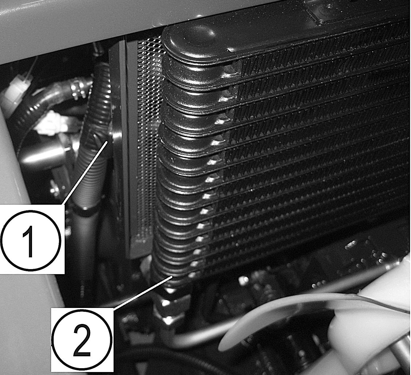
20. RADIATOR
IMPORTANT: a. Wipe off the dust by using a piece of cloth or the like. b. The clogged radiator fins should be cleaned by applying compressed air or water from both sides alternatively. c. Re-install the radiator screen.
・The radiator screen(2) and radiator clogged with dust or dirt causes overheating of the engine due to reduced cooling efficiency of the radiator.
・The radiator and radiator screen should be checked for clogging everyday before operation.
・When mowing dead grass or operating under extremely dusty conditions, check the radiator screen and radiator several times a day to avoid clogging.
The radiator is located at the middle of right hand side of the front mower. .
IMPORTANT:
・Avoid using excessively compressed air or water, which may deform the cooling fin.
・Avoid applying water directly to the wiring and electric parts.
・After washing the radiator using water, let it dry by natural drying.
(1) Radiator net
21. COOLANT REPLACEMENT
WARNING: Never attempt to remove the radiator cap during or just after operation, or pressurized vapor and hot water will gush out, which may cause burns. So wait until the engine cools down sufficiently.
The drain plug of the engine coolant is located on the right hand side rear part of the front mower.
a. Place a coolant receiver under the drain hose, 1. Remove the bolt,2. Disconnect the radiator hose.
(1) Drain plug
FIG. 83
FIG. 84 b. Remove the radiator cap, 2, and the drain plug to let all coolant drain out of the radiator and engine cylinder block. c. When all coolant completely drained out, wash the inside of the radiator and tighten the drain plug securely. d. Pour the coolant which has a specified antifreeze concentration until it starts overflowing through the coolant filler. Retighten the radiator cap securely.
Radiator2.5 liters
Reserve tank1.0 liters
WARNING: Be sure to tighten the radiator cap securely, or boiling coolant may shoot out, which is very dangerous.
IMPORTANT: e. After filling, start the engine and let it idle for 5 minutes or so. Then check the coolant level. If the level is low, replenish the reserve tank with coolant in referring to "4. COOLANT LEVEL".
・Frozen coolant may damage the engine.
・ Mixing ratio of water and antifreeze is different by antifreeze manufacturers and atmospheric temperatures.
・ Water and antifreeze should be blended sufficiently beforehand.
IMPORTANT: Never attempt to run the engine without coolant, or the engine will seize, leading to its complete damage.
IMPORTANT: When replacing coolant (at the engine cool down), remove the air plug and bleed air, otherwise it may result in engine broken. When coolant is full, tighten plug, and replenish coolant from the radiator cap, 2.
22. FUSES AND WIRING
The fuse box, 2, is located under the seat, 1. Ref Fuse capacity Function
A5AGlow1
B5AGlow2
C5APump relay
D5ASolenoid relay
E5ATimer relay
F15AController
G10AMater panel
H15ATurn lamp (ACC)
I20AMotor
J15ATurn lamp (B)
K10APosition horn
L20AHead lamp
M10ABrake lamp
N10ABeacon lamp
O20AOption (B)
P10AStarter relay
CAUTION: Never replace blown fuses or slow-blow fuse with wire.
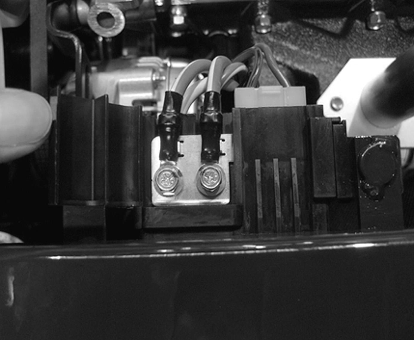
The slow-blow fuse boxes are located at left hand side of radiator.
To replacing 60A and 50A slow blow fuse, follow the steps:
1. Open the fuse box cover,1, from top side of fuse box.
2. Loosen the bolt.
Bolt for 60A - 2
Bolt for 50A - 3
IMPORTANT:
・When a fuse or a slow-blow fuse is blown, be sure to find the trouble and correct it. When the cause is not clear, consult your dealer.
・Be sure to use specified fuses. Larger-capacity fuses will cause burn-out of electric accessories and wiring.
(3) Slow-blow fuse (60A)
(4) Slow-blow fuse (50A)
(5) Slow-blow fuse (40A)
IMPORTANT: When a slow-blow fuse has been blown out, use genuine slow-blow fuse.
Slow - blow fuseParts code
40A1650-650-222-00
50A1832-690-203-00
60A 3829-260-303-00
WARNING: Damaged wire covers should be mended with insulation tape immediately.
CAUTION:
・The wiring of the front mower should be checked every year at your dealer to avoid electrical fires.
・Grass and dust around the battery, wiring, muffler and engine should be removed. Otherwise they may catch fire.
IMPORTANT: When a wire harness has come off its clamp, it should be re-clamped immediately.
Harness coupler for beacon lamp, is located in the behind of the oil cooler.
23. HYDRAULIC SYSTEM PARTS
When hydraulic system parts such as the HST unit, hydraulic pump, control valve, hydraulic cylinder, piping, etc. are required to be adjusted or repaired, consult your ISEKI dealers. Users are advised not to adjust or repair hydraulic system parts by themselves.
24. SAFETY SWITCHES
Safety devices are installed for safe operation. Make sure that each device works properly before operation following procedures.
CAUTION: When the engine does not start due to a defective safety switch or does not stop when the operator has left the operator's seat, consult your dealer.
Inspection 1
a. Be seated in the operator's seat.
b. Turn the starter switch to the START position without depressing the brake pedal. Make sure that the engine is not cranked.
INSPECTION 2 a. Be seated in the operator's seat. b. Depress the brake pedal fully. c. Turn the starter switch to the START position. Make sure that the engine is cranked and started. d. Leave from the operator's seat. Make sure that the engine should stop.