INTRODUCTION GENERAL This section has the description of the frame and some connected parts. See FIGURE 1. Procedures for the removal and installation of the counterweight, hood, overhead guard, and engine (including the transmission) are under REPAIRS. Checks for the operator restraint system and procedures for the repair of tanks and replacement of safety labels are also included.
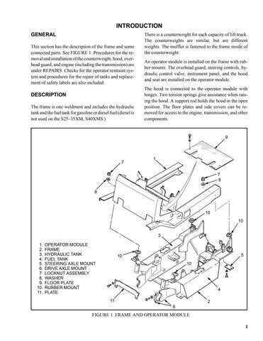
DESCRIPTION The frame is one weldment and includes the hydraulic tank and the fuel tank for gasoline or diesel fuel (diesel is not used on the S25–35XM, S40XMS.)
There is a counterweight for each capacity of lift truck. The counterweights are similar, but are different weights. The muffler is fastened to the frame inside of the counterweight. An operator module is installed on the frame with rubber mounts. The overhead guard, steering controls, hydraulic control valve, instrument panel, and the hood and seat are installed on the operator module. The hood is connected to the operator module with hinges. Two torsion springs give assistance when raising the hood. A support rod holds the hood in the open position. The floor plates and side covers can be removed for access to the engine, transmission, and other components.
9
7
1
7 8 8
10 10 3 1. 2. 3. 4. 5. 6. 7. 8. 9. 10. 11.
OPERATOR MODULE FRAME HYDRAULIC TANK FUEL TANK STEERING AXLE MOUNT DRIVE AXLE MOUNT LOCKNUT ASSEMBLY WASHER FLOOR PLATE RUBBER MOUNT PLATE
5
10 10
4 11
2 6
FIGURE 1. FRAME AND OPERATOR MODULE 1
