INTRODUCTION GENERAL This section has the description, operation, checks and adjustments for the parts of the electric power steering (EPS) system. The system electrically controls a motor to turn the master drive unit for steering. This section is NOT for lift trucks that have the wire guidance system. See the sections WIRE GUIDANCE, DESCRIPTION, 2200 SRM 317, section to adjust or WIRE GUIDANCE, REPAIR, 2200 SRM 321, to repair the parts of the EPS system used on lift trucks with wire guidance.
to turn the drive sprocket. The drive sprocket moves the chain to turn the MDU on the spindle. The steering potentiometer is turned by a gear on the MDU spindle. The potentiometer tells the ECM the position of the MDU.
DESCRIPTION (See FIGURE 1.) The electric power steering system has no cables or hydraulic lines between the steering wheel and the Master Drive Unit (MDU). The system uses electrical signals to control an electric motor and gear box to turn the MDU. An electrical signal generated by turning the steering wheel is an input to a control module that operates the motor. Other inputs are also used for correct steering control. The following parts are in the system: a. Steering wheel, gears and steering generator b. Two wires in an 18 conductor cable between the steering generator and electrical compartment c. The Electronic Control Module (ECM) d. The electric motor, worm reduction gear and chain to the MDU e. The steering potentiometer f. The automatic shut–off card. The speed and direction of rotation of the steering wheel sets the voltage and polarity of the generator signal. The generator signal varies from zero to a plus voltage and from zero to a minus voltage to indicate steering rate and direction. The steering wheel and gears turn the shaft of the signal generator. The ECM uses the inputs from the steering generator and steering potentiometer to control the power to the steering motor. The ECM is fastened to the electrical compartment door or panel. The door or panel is a heat sink for the module. The steering motor is a permanent magnet motor. The steering motor turns the worm reduction gear
11028
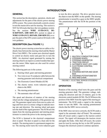
1. 2. 3. 4. 5. 6. 7. 8. 9. 10.
MULTIPLE CONDUCTOR CABLE STEERING WHEEL STEERING GENERATOR TRACTION CIRCUIT AUTOMATIC SHUT–OFF CARD ELECTRONIC CONTROL MODULE BATTERY STEERING MOTOR AND GEAR BOX STEERING POTENTIOMETER MDU AND CHAIN
FIGURE 1. ELECTRIC POWER STEERING PARTS
OPERATION Rotation of the steering wheel turns the gears and the steering generator shaft. The generator voltage, indicating the direction and rate of rotation, goes to the electronic control module (ECM). The ECM knows the position of the MDU from the signal of the steering potentiometer. The ECM sends a signal to the steering motor to turn the MDU. The steering potentiometer checks that the MDU moves correctly. If the MDU does not move correctly, the ECM sends a signal to the automatic shut–off board. The automatic shut–off circuit sends a signal to the traction control circuit. The signal will deenergize the traction circuit and apply the brake. After shut–off occurs, the system must be reset by moving the key to the OFF position. Energize the electrical system to continue operation. 1
