9 minute read
090 - Chassis

from Gehl AL550 Mustang AL508 Manitou MLA 5-60 Articulated Loader Service Manual 50940658 - PDF DOWNLOAD
ROPS/FOPS Mounting
38CAB ENCLOSURE/AL550
Advertisement
38 OPEN CANOPY/SPLITABLE
46SHEET/FRONT COVER
104 BHFSCS M6-1.00x16 C10.9 BO ISO7380-2
110M20-2.50X130 C10.9 BOLT
120 CS M12-1.75X25 C8.8 ZY DIN933
252NUT/M6X1.0 CLIP 10
ROPS/FOPS Removal
NOTE: Label all hoses, tubes, and electrical connections. Note their locations before disconnecting to ensure correct installation.
NOTE: Cap and plug all exposed coolant/ hydraulic system openings to prevent contamination.
IMPORTANT: Park the machine where the ROPS/FOPS cab/canopy can be removed with a suitable lifting device.
Warning
The ROPS/FOPS weighs approximately 454 kg (1000 lbs.). Do NOT use any lifting attachments (slings, chains) that are damaged or of inadequate rated capacity. Lifting the ROPS/ FOPS without proper equipment could result in serious personal injury or equipment damage. Keep clear of suspended loads.
Never lift with anyone in, on, or under the ROPS/ FOPS.
1.Park the machine where the ROPS/FOPS cab/ canopy can be removed with a suitable lifting device.
2.Complete the Mandatory Safety Shutdown Procedure. See “Mandatory Safety Shutdown Procedure” on page24.
Caution
The air conditioning system must be serviced only by trained staff in authorized workshops. Some localities may require HVAC certification. Check state and local regulations for requirements.
3.On machines equipped with air conditioning, recover the refrigerant from the air conditioning system. See “Air Conditioning Refrigerant Recovery” on page108.
4.Open the engine cover.
5.Turn the battery disconnect switch to the OFF position.
6.On machines equipped with an enclosed cab, drain the cooling system according to the Operator’s Manual.
IMPORTANT: Dispose of waste coolant according to environmental laws. DO NOT pour coolant onto the ground or down a drain.
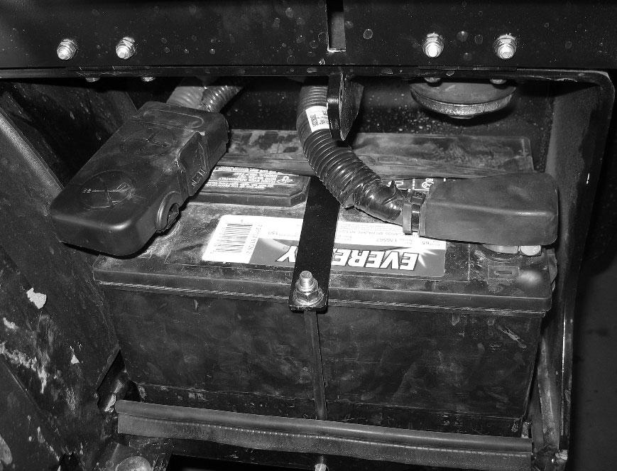
7.Disconnect the negative battery cable from the negative (-) battery terminal (A, Fig. 217).
8.Disconnect the positive battery cable from the positive (+) battery terminal (B).
9.Remove the fasteners (C) securing the battery tie-down (D). Remove the battery from the machine.
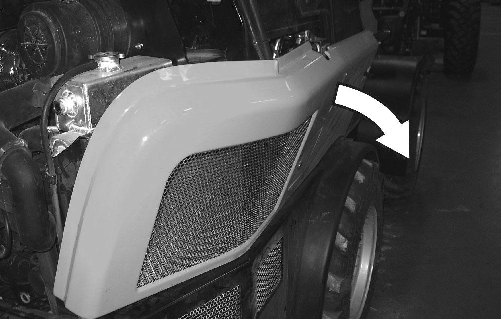
10.Remove the side panels according to “Side Panel Removal/Replacement” on page237.
NOTE: The fasteners described in the following step may vary from what is shown.
11.On machines with air conditioning: a.Remove the fasteners and hose clamps (E, Fig. 218) securing the air conditioning condenser hose guard (F) at the right rear corner of the ROPS/FOPS. Remove the hose guard (F). b.Remove the fasteners (G, Fig. 219) that secure the AC condenser cover (H). Remove the condenser cover from the machine. d.Disconnect the HVAC electrical connection (K, Fig. 221) [C-HRF-138-2] at the bottom right rear corner of the ROPS/FOPS. c.At the top rear right corner of the ROPS/ FOPS, disconnect the air conditioning hoses (I, Fig. 220) from the condenser (J). Cap/ plug openings to prevent contamination.


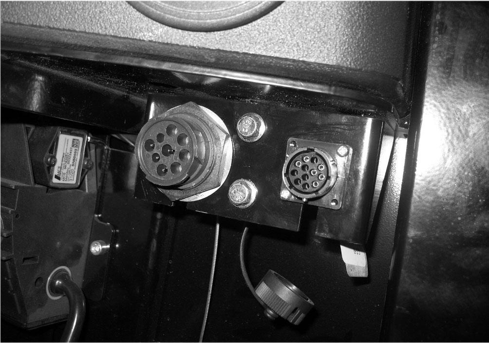
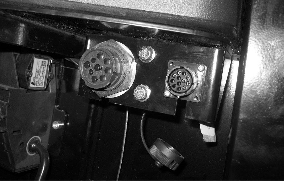
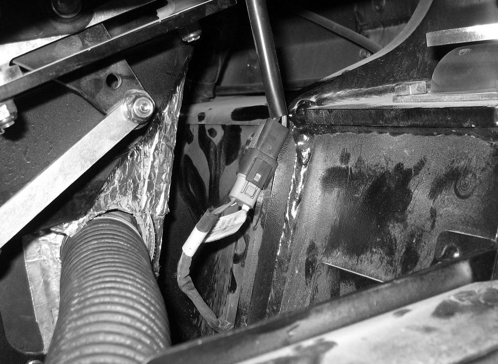
12.Disconnect the ROPS electrical connection (L) at the bottom right rear corner of the ROPS/ FOPS.

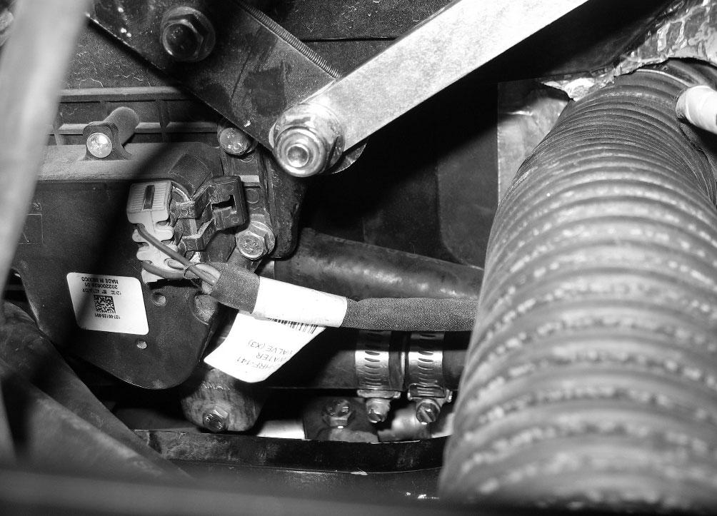
13.On machines equipped with heat/air conditioning, on the left side of the machine: a.Disconnect the electrical connection (M, Fig. 222) at the heat/air conditioning unit. b.Loosen the hose clamps fastening the heater hoses (N) to the heat/air conditioning unit. Remove the heater hoses from the unit. c.Disconnect the hose (O, Fig. 223) from the back of the cab air filter box (P).
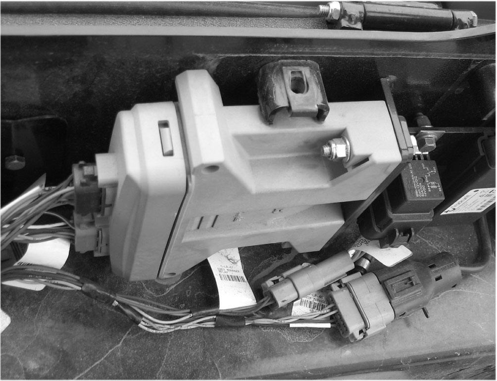
14.Disconnect the parking brake electrical connection (Q, Fig. 224) [C-RF-100] on the left side of the machine.


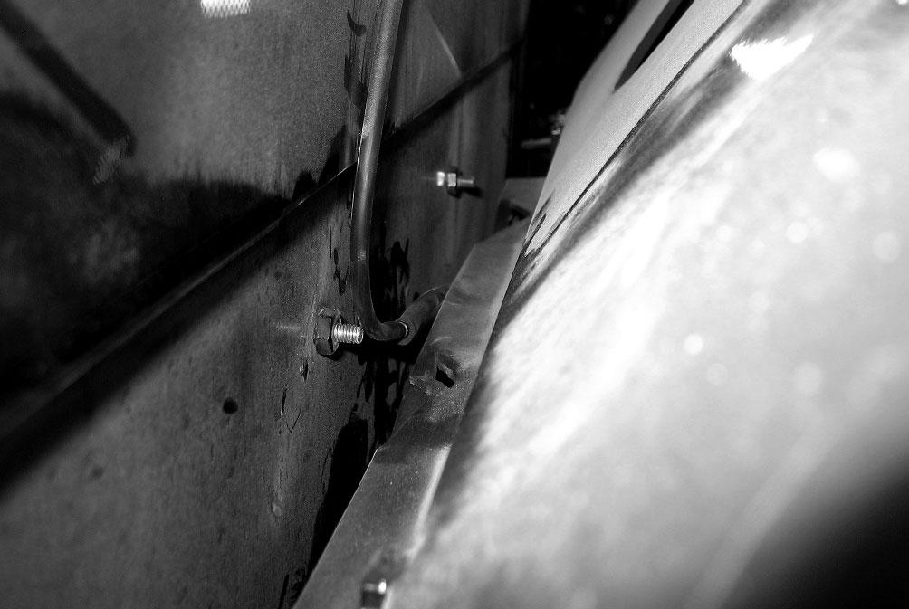
17.Remove the fastener (U, Fig. 226) securing the ROPS/FOPS ground cable (V) to the ROPS/ FOPS.

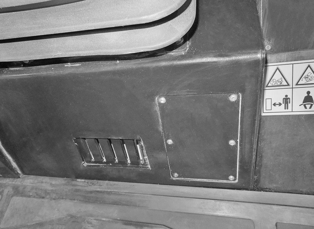
19.At the front of the ROPS/FOPS, disconnect the electrical connections (Y, Fig. 228):
18.At the front of the ROPS/FOPS, remove the screws (W, Fig. 227) fastening the steering valve access panel (X).


•Steering column connection [C-RF-40A]
•Steering column connection [C-RF-11A]
•Control stalk connection [C-RF-9] (On machines equipped with optional road lights).
20.If the ROPS is equipped with a front windshield wiper, disconnect the windshield washer hose (Z, Fig. 229).
NOTE: Some hydraulic oil and brake fluid will leak when removing hoses. Use an appropriate sized container for catching leaking fluids.
21.Label and disconnect the five hydraulic hoses (A, Fig. 230) from the steering valve. Cap/plug openings to prevent contamination.


22.Label and disconnect the brake hose (B, Fig. 231) from brake master cylinder. Cap/ plug openings to prevent contamination.
24.On machines with air conditioning: a.Disconnect the air conditioning lines (E, Fig. 233) from the air conditioning unit. Cap and plug openings to prevent contamination. b.Disconnect the electrical connection (F) for the HVAC blower [C-HRF-145] from the chassis harness.

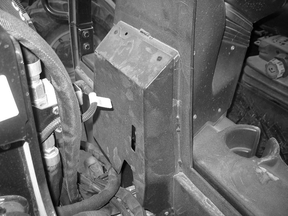
23.On machines equipped with heat/air conditioning, remove the fasteners (C, Fig. 232) securing the kick plate access panel (D).
090 - Chassis
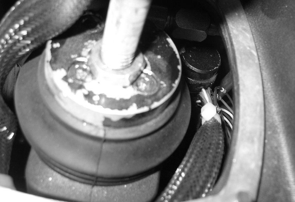
25.Lift the rubber boot (G, Fig. 234) around the joystick to allow access to the joystick mount.

26.Loosen the joystick locking nut (I, Fig. 235).
Warning
The ROPS/FOPS weighs approximately 454 kg (1000 lbs.). Do NOT use any lifting attachments (slings, chains) that are damaged or of inadequate rated capacity. Lifting the ROPS/ FOPS without proper equipment could result in serious personal injury or equipment damage. Keep clear of suspended loads.
Never lift with anyone in, on, or under the ROPS/ FOPS.
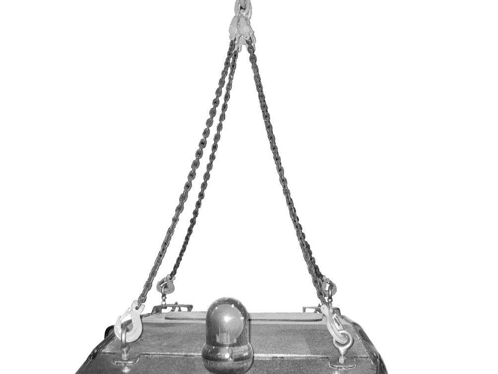
30.Install M16 lifting eyebolts (L, Fig. 237) into each of the threaded holes in the corners on top of the ROPS/FOPS.
27.Disconnect the joystick wire connector from the chassis harness [C-LR-70].
28.Loosen and remove the joystick from the control valve (J).
29.If the ROPS is equipped with a rear window wiper, disconnect the rear window washer hose at the splice (K, Fig. 236).

31.Attach a suitable lifting device (M, Fig. 238) to the lifting eyebolts.
33.Slowly and carefully remove the ROPS/FOPS from the machine. Carefully set the ROPS/FOPS on jack stands or wood blocks.
Warning
Position the ROPS/FOPS so it will not tip over. Serious injury and damage can occur if the ROPS/FOPS tips over.
ROPS/FOPS Installation
Warning
32.Remove the nuts, screws, and flat washers (W, Fig. 239) securing the ROPS/FOPS to the chassis.
The ROPS/FOPS weighs approximately 454 kg (1000 lbs.). Do NOT use any lifting attachments (slings, chains) that are damaged or of inadequate rated capacity. Lifting the ROPS/ FOPS without proper equipment could result in serious personal injury or equipment damage. Keep clear of suspended loads.
Never lift with anyone in, on, or under the ROPS/ FOPS.
1.Install M16 lifting eyebolts (L, Fig. 240) into each of the threaded holes in the corners on top of the ROPS/FOPS.
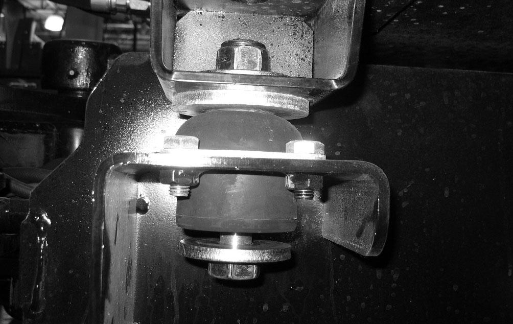
NOTE: The left front ROPS/FOPS mounting point is shown. The remaining mounting points are similar.
IMPORTANT: Lift the ROPS/FOPS slowly and carefully. Check all disconnection points to ensure all necessary hoses, tubes, wires, and cables have been disconnected and will not be damaged during ROPS/FOPS removal.
2.Attach a suitable lifting device (M, Fig. 241) to the lifting eyebolts.
7.Tighten the fasteners and nuts (E) to 370 Nm (273 ft.-lbs.).
8.Remove the lifting device and lifting eyebolts from the ROPS/FOPS.
9.If the ROPS/FOPS is equipped with a rear window wiper, connect the rear window washer hose at the splice (K, Fig. 243).
3.Make sure all wires, hoses, etc. are positioned for connection once the ROPS/FOPS is positioned onto the chassis.
4.Position the flat washers (C, Fig. 242) onto the ROPS/FOPS mounts.
10.Thread the joystick all the way onto the control valve (J, Fig. 244).
5.Slowly and carefully lower the ROPS/FOPS onto the mounts. Make sure all harnesses, hoses, lines and cables are not pinched or binding.
6.Secure the ROPS/FOPS at all four mounting points with screws, nuts (E) and flat washers (D).
NOTE: The left front ROPS/FOPS mounting point is shown. The remaining mounting points are similar.
11.Rotate the joystick as necessary so the trigger button is pointing to the front of the machine.
12.Tighten the joystick locking nut (I) to secure the joystick in position.
13.Plug the joystick wire connector into the chassis harness [C-LR-70].

14.Pull the rubber boot (G, Fig. 245) down around the joystick. Tuck the edges of the boot under the joystick boot retainer plate (I).
16.Remove the caps/plugs and connect the brake hose (B, Fig. 248) to the brake master cylinder. Tighten securely.
15.On cab-equipped machines: a.Connect the electrical connection for the HVAC blower (F, Fig. 246) under the ROPS/ FOPS to the chassis harness [C-HRF-145]. b.Remove the caps/plugs and connect the air conditioning hoses (E) to the air conditioning unit. Tighten securely. c.On machines with air conditioning, fasten the kick plate access panel (D, Fig. 247) using the screws (C). Tighten securely.
17.Remove the caps/plugs and connect the hydraulic hoses (A, Fig. 249) to the steering valve. Tighten securely.
18.If the ROPS is equipped with a front windshield wiper, connect the windshield washer hose (Z, Fig. 250).
•Steering column connection [C-RF-40A and C-S-40B]
•Steering column connection [C-RF-11A and C-S-11B]
•On machines equipped with optional road lights: control stalk connection [C-RF-9 and control stalk wiring connector]
20.Secure the ROPS/FOPS ground cable (V, Fig. 252) to the bottom of the ROPS/FOPS using the fastener (U). Tighten securely.
19.Connect the electrical connections (Y, Fig. 251) between the steering column and the chassis harnesses at the front of the ROPS/FOPS:
21.Fasten the parking brake clevis (T, Fig. 253) on the parking brake cable to the parking brake bellcrank (S).
25.On machines equipped with heat/air conditioning: a.Plug the HVAC harness electrical connector (M, Fig. 255) [C-HRF-145] into the heat/air conditioning unit. b.Connect the heater hoses (N) to the heat/air conditioning unit. Fasten the heater hoses with the hose clamps. Tighten securely. c.Slide a hose clamp onto the cab filter hose (O, Fig. 256) before performing the next step. d.Connect the cab air filter hose (O) to the back of the cab air filter box (P). Fasten the hose (O) with the hose clamp. Tighten securely. b.Secure the air conditioning condenser cover (H, Fig. 259) onto the condenser enclosure using the fasteners (G).
22.Insert the parking brake cable adjuster (T) into parking brake cable mount (W).
23.Adjust the parking brake cable using the adjuster (T). Tighten the adjuster (T) to lock the cable adjustment.
NOTE: Adjust so the parking brake cable becomes slack only when the parking brake lever is all the way down.
24.Connect the parking brake electrical connection (Q, Fig. 254) to the chassis harness [C-RF-100].
26.Connect the ROPS electrical connection (L, Fig. 257) at the bottom right rear corner of the ROPS/ FOPS.
NOTE: The fasteners described in the following two steps may vary from what is shown.
27.On machines equipped with heat/air conditioning, connect the HVAC electrical connection (K) [C-HRF-138-2] at the bottom right rear corner of the ROPS/FOPS.
28.On machines with heat/air conditioning: a.At the top rear left corner of the ROPS/ FOPS, remove the caps/plugs and connect the air conditioning hoses (I, Fig. 258) to the condenser (J). Tighten securely. c.Attach the hose guard (F, Fig. 260) and the air conditioning condenser hoses at the left rear corner of the ROPS/FOPS using the fasteners and hose clamps (E).
29. Position the battery inside the battery compartment. Secure the battery with the tiedown (D, Fig. 261) and the fasteners (C).
Warning
NEVER use your hands to search for hydraulic oil leaks when the machine is running. Use a piece of cardboard or paper if necessary to check for leaks when the machine is running. Escaping oil under pressure can be invisible and penetrate the skin causing serious injury. If any oil is injected into your skin, get medical attention immediately. Injected fluid MUST be surgically removed by a doctor familiar with this type of injury or gangrene may result.

Warning
30.Connect the positive battery cable to the positive (+) battery terminal (B). Tighten securely.
31.Connect the negative battery cable to the negative (-) battery terminal (A). Tighten securely.
32.Check the hydraulic oil level and if necessary add hydraulic oil according to the Operator’s Manual.
33.Fill the cooling system as necessary with the proper amount and grade of coolant according to the Operator’s Manual.
34.Bleed the brake system according to “Bleeding the Brake System” on page 103
35.Adjust the parking brake according to “Parking Brake Adjustment/Service” on page 104.
36.Turn the battery disconnect switch to the ON position.
37.Start the engine and operate the machine for a minute or two.
38.Stop the engine. Check for hydraulic/coolant leaks. Tighten/repair as required.
ALWAYS wear safety glasses when checking for hydraulic fluid leaks when the machine is running. Escaping fluid under pressure can be invisible and can cause permanent eyesight damage if safety glasses are not worn.
39.Check the hydraulic oil and coolant levels. Add fluids if necessary.
Caution
The air conditioning system must be repaired, serviced, and filled with refrigerant only by trained staff and in a workshop authorized in air conditioning maintenance.
40.Charge the air conditioning system according to “Air Conditioning System Charging” on page108.
41.Fasten the steering valve access panel (X, Fig. 262) to the front of the ROPS/FOPS using the screws (W).

Engine Cover Removal/Replacement
Caution
Engine cover removal/replacement requires two people. Use care during removal to prevent damaging the engine cover.
Engine Cover Removal
1.Open the engine cover and support it with an appropriate lifting device.
2.Remove the nut (A, Fig. 263) securing the pneumatic strut (B) to the bracket (Z) on the engine cover. Remove the strut (B) from the bracket (Z).
42.Replace the side panels according to “Side Panel Removal/Replacement” on page237.
43.Close the engine cover.
3.Carefully close the engine cover.
IMPORTANT: Do not remove/loosen the engine cover hinge brackets. Changing the hinge bracket location will put the engine cover latch out of adjustment. This can prevent the engine cover from closing properly.
4.Remove the nuts (C, Fig. 264) securing the hinge pin screws (D) in the engine cover hinge brackets. Slide the screws (D) out of the hinge brackets.

5.Insert the pneumatic strut (B, Fig. 266) into the bracket (Z) on the underside of the engine cover. Secure the strut (B) using the nut (A). Tighten securely.
5.With an assistant, carefully remove the engine cover. Store the cover in a clean, safe location.
Engine Cover Replacement
1.With an assistant, carefully position the engine cover in place on the machine.
2.Align the hinge halves and slide the screws (D, Fig. 265) through the hinges.
6.Remove the support and close the engine cover.
3.Secure the screws (D) in the hinges using the nuts (C).
4.Open the engine cover and support it with an appropriate lifting device.
Articulation Joint Components
2RETAINER/BEARING
3BEARING/SPHERICAL
4CAP/BEARING
5 WASHER/BEARING SHIELD
6RING RETAINING
13 BEARING/SPHERICAL PIVOT
17
24
CS M20-2.5X40 C10.9 ZY DIN933
CS M10-1.5x25 C8.8 ZY DIN933
34RING/RETAINING
35 HOUSING/BEARING PIVOT
36FITTING/GREASE M10X1
37FITTING/GREASE M6X1