1 minute read
090 - Chassis

from Gehl AL550 Mustang AL508 Manitou MLA 5-60 Articulated Loader Service Manual 50940658 - PDF DOWNLOAD

Chassis General Information
The chassis consists of the front and rear frame, the articulation steering joint in the center of the machine and the cab/canopy.
Advertisement
Side Panel Removal/Replacement
The left and right panels on the side of the machine can be removed for inspection and service.
To remove the side panels:
1.Open the engine cover.
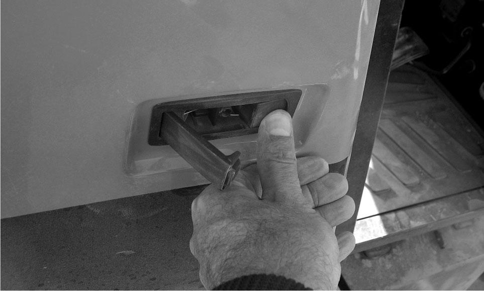
2.On the right side panel, press the release (F, Fig. 208) as shown to open the front latch.

4.Lift the panel off of the machine and store it in a clean, safe location.
To replace the side panels:
1.Insert the catches (T, Fig. 210) on the bottom inside of the side panel fully into the slots (U) on the chassis.
090 - Chassis
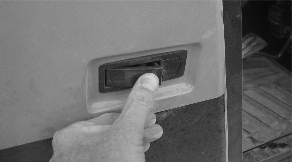
3.On the right side panel, push the front of the panel tightly against the machine and push the front latch (G, Fig. 211) closed until it clicks.

4.Close the engine cover.
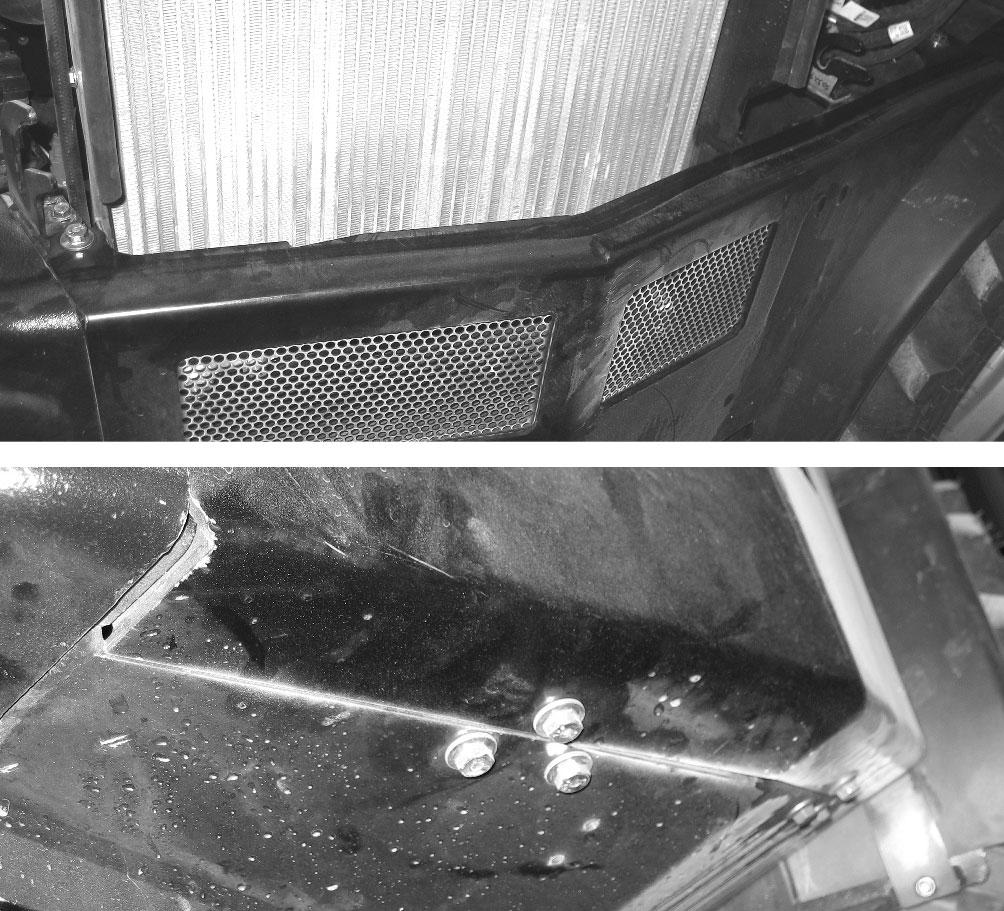
Removing the right panel provides access to (Fig. 212):
•HVAC fuse box (Y)
•Parking brake lever linkage (Z).
•Hydraulic oil filler neck (A)
•Hydraulic oil filter (B)
•Hydraulic oil level sight gauge (C)
•Radiator (D).
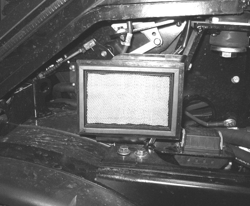
Removing the left panel provides access to:
•HVAC cab filter (E, Fig. 213)
Rear Cover Removal/Replacement
Caution
The service covers (B, Fig. 214 and Fig. 215) weigh approximately 22 kg. (50 lbs.). Have an assistant help when removing/replacing the service covers.
1.Have an assistant support/position the rear cover (B).
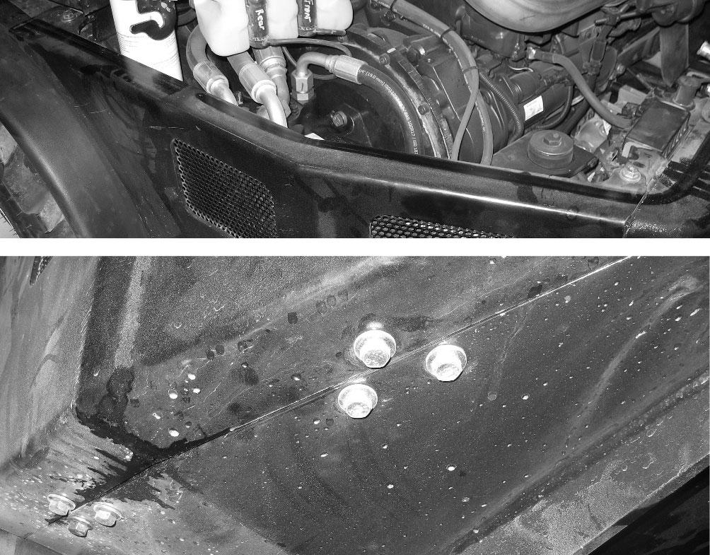
Service Cover Removal/Replacement
The service covers (X, Fig. 216) are located under the machine at the rear. They can be removed for inspection, maintenance and service.

Caution
The service covers (X) weigh approximately 11 kg. (25 lbs.). Use care when removing the service covers. Injury can result from a falling service cover.
Service cover (X) removal:
1.Support the service cover (X).
2.Remove/attach the rear cover using the two screw on top (A) and the two on the bottom (C).
2.Loosen and remove the fastener (P) securing the service cover (X).
3.Carefully lower and remove the service cover (X).
NOTE: The lip at the front service cover hooks onto the chassis.
Service cover (X) replacement:
1.Lift the service cover (X) in place under the machine.
NOTE: The lip at the front service cover hooks onto the chassis.
2.Have an assistant hold the service cover in place on the (X) machine and secure it using the fastener (P).
3.Tighten the fastener (P) securely.