CHAPTER 9 SERVICE GENERAL INFORMATION
Valves Internal component service on any of the hydraulic valves should only be performed by (or under the direction of) an authorized GEHL dealer. Access to the hydraulic valves is gained by unbolting the access covers. After the hydraulic connections and mechanical linkages are carefully marked and removed, remove the valve and take it to your dealer for service or replacement.
CAUTION BEFORE servicing the loader, unless expressly instructed to the contrary, exercise the MANDATORY SAFETY SHUTDOWN PROCEDURE (page 8). After service has been performed, BE SURE to restore all guards, shields and covers to their original positions BEFORE resuming loader operation.
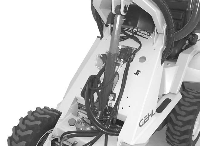
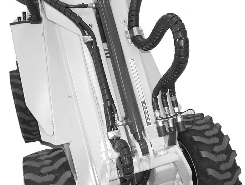
Cylinders All hydraulic cylinders used on the loader are appropriately designed with particular strokes, diameters and hose connection provisions unique to the loader application requirements. In addition, internal cylinder component service and replacement requires special know-how and tools. Any of the hydraulic cylinders can be removed from the loader and taken to the dealer for service or replacement. To remove a cylinder from the loader, proceed as follows: 1. Be sure that the lift arm is lowered and in contact with the loader frame. 2. Exercise the MANDATORY SAFETY SHUTDOWN PROCEDURE (page 8). 3. Relieve ALL pressure in the lines by moving the drive and lift/tilt controls in all directions. 4. Disconnect the hydraulic hose connections at the desired cylinder. 5. Remove the rod-end anchor pin first. 6. Lastly, remove the cylinder-end anchor pin. Cylinder replacement is in reverse order of removal.
IMPORTANT: Whenever service is performed on hydraulic components, (valves, cylinders, hoses, etc.) transmissions or engines care must be taken to prevent discharging fluids onto the ground. Catch and dispose of fluids per local waste disposal regulations. This Service chapter details procedures to follow for making routine maintenance checks, adjustments and replacements. For engine related adjustments and servicing procedures, BE SURE to refer to the separate Engine Operator’s Manual provided.
DEALER SERVICES The following areas of internal components service, replacement and operating adjustments should only be performed (or under the direction of) an authorized GEHL dealer.
OPERATOR SERVICES Check Engine Oil Level (Fig. 24)
Hydraulic Components The hydraulic pumps are coupled directly to each other (in tandem) and to the engine crankshaft. All service routines related to the internal components of the pumps are precise and critical to proper operation. The hydraulic drive motors are complex devices that require special know-how and tools for servicing.
Unlatch and remove the engine access cover. Pull out the dipstick, located on the left side of engine, and check the oil level. Markings on the dipstick represent both full and low (add oil) levels. Refer to the separate Engine Operator’s Manual for the proper location and procedures for adding/changing engine oil. Also, refer to the separate Engine Operator’s Manual for oil requirements information. A hole in the loader bellyplate gives access to the engine oil drain.
NOTE: If a hydraulic pump or drive motor is suspected of faulty operation, contact your GEHL dealer for further information and directives.
918024/BP0207
34
Printed in U.S.A.