4 minute read
CHAPTER 1 INTRODUCTION

from Gehl AL20DX Series II Articulated Compact Utility Loader Operator's Manual 918024 - PDF DOWNLOAD

This Operator’s Manual gives the owner/operator information about maintaining and servicing the AL20DX Series II articulated compact utility loader. More importantly, this manual provides an operating plan for safe and proper use of the machine. Major points of safe operation are detailed in the Safety chapter of this manual.
We ask that you read and understand the contents of this manual completely and become familiar with your new machine before operating it. See your authorized Gehl dealer if you have any questions concerning information in the manual, require additional manuals or for information concerning availability of manuals in other languages.
Throughout this manual, information is provided which is set in italic type and introduced by the word NOTE or IMPORTANT. BE SURE to read carefully and comply with the message it will improve your operating and maintenance efficiency, help avoid breakdowns and damage, and extend your machine’s life.
A manual storage box behind the operator’s seat holds the Operator’s Manual and AEM Safety Manual. Please return the manuals to this box and keep them with the unit at all times. If this machine is resold, we recommend that these manuals be given to the new owner.
If this machine was purchased ‘‘used,” or if the owner’s address has changed, please provide your Gehl dealer or Gehl Company Service Department with the owner’s name and current address, along with the machine model and serial number. This will allow the registered owner information to be updated, so that the owner can be notified directly in case of an important product issue, such as a safety update program.
The attachments and equipment available for use with this machine have a wide variety of potential applications. Read the manual provided with the attachment to
Typical Model & Serial Number Plate
learn how to safely maintain and operate the equipment. BE SURE the machine is suitably equipped for the type of work to be performed.
DO NOT use this machine for any applications or purposes other that those described in this manual or applicable for approved attachments. If the machine is to be used with special attachments other than those approved by Gehl, consult your Gehl dealer. Any person using non-approved attachments is responsible for the consequences.
The Gehl dealership network stands ready to provide you with any assistance you may require, including providing genuine Gehl service parts. All service parts should be obtained from your Gehl dealer. Give complete information about the part and include the model and serial numbers of your machine. Record the serial number in the space provided above as a handy record for quick reference.
The model and serial numbers for this unit are on a tag located on a panel behind the right front wheel.
‘‘Right’’ and ‘‘left’’ are determined from a position sitting on the seat and facing forward. From this position, the hand throttle and hydraulic controls are on the ‘‘right’’.
Please be aware that Gehl Company strives to continuously improve its products and reserves the right to make changes and improvements in the design and construction of any part without incurring the obligation to install such changes on any unit previously delivered.
Chapter 2 Specifications
All Dimensions are in Inches (Millimeters) Unless Otherwise Noted
Model & Description
AL20DX Series II . . . . . . . . . . . .
Articulated Compact Utility Loader
Engine20 hp (14.9 kW) Kubota Diesel Liquid Cooled
Overall Length88 (2226)
Overall Width40 (1016)
Overall Height (to top of ROPS)78 (1901)
Ground Clearance8 (206)
Weight - approximate2,006 lb (910 kg) . . . . . . . . . . . . .
Steering Wheel2.7/4.2 turns stop-to-stop
Turning Radius Inside34-5/8 (880)
Outside78-3/4 (2000)
Lift Height (Telescopic Boom)94-1/2(2400)
Max. Pulling Force1799 lb (8500 N)
Max. Drive Speed6.8 mph (10.9 km/h)
Hydraulic Flow and Pressure Loader Hydraulics5.3 or 10.6 gpm @ 2900 psi . . . . (20 or 40 L/min @ 20000 kPa)
Drive18.1 gpm @ 3990 psi (68 L/min @ 27500 kPa)
R.O.P.S.
Deluxe Suspension Seat Seatbelt, Armrests
Controls:
Steering Wheel
Single Joystick Boom and Bucket Tilt
Hand Throttle
Foot-operated Directional Control
Battery 12-Volt
Electric Start
4-Wheel Drive
Auxiliary Hydraulics Flat-faced Couplers
Lift Arm Support Device
Steering Frame Lock
Hydraulic Oil Cooler
Quick Attachment System - Avantage attachments
Operator’s Manual Storage Box
Telescoping Load Arm
Hand Brake
Optional
(straight lift, 175 lb. (80 kg) driver and 66 lb. (30 kg) counterweight, on flat even surface.)
Volumetric
Displacement44 cu. in. (719 cm3)
Valve Clearance (suction)(0.145-0.185)
Valve Clearance (exhaust)(0.145-0.185)
Sound Pressure Level (LPA)89
Standard
Multi-purpose (4-in-1) Bucket
Counterweight Rear
Work Light Front
F.O.P.S.
See your dealer for other available attachments, accessories and trailer packages.
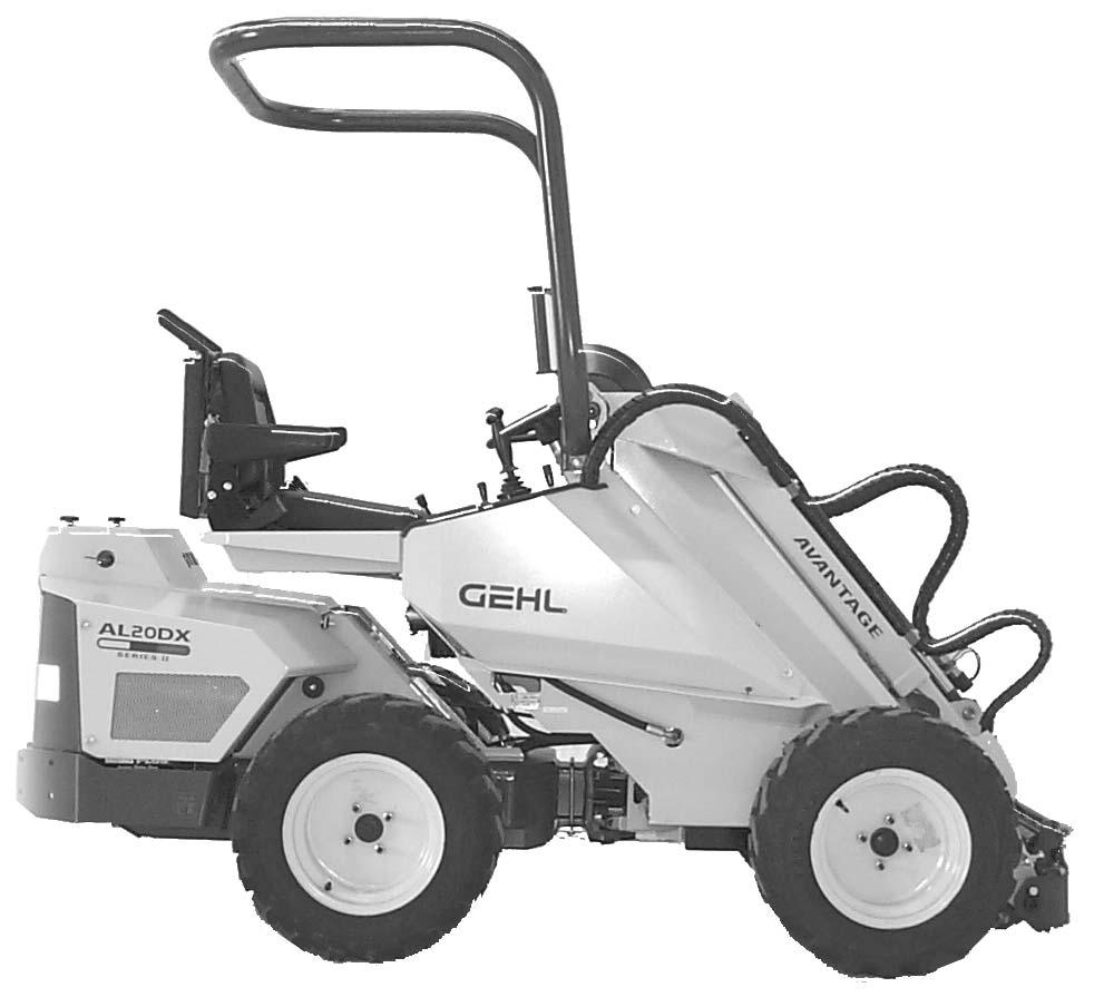
1.FRONT FRAME
This part of the loader is located in front of the articulation joint. On the front frame the following are mounted: driver’s seat, operating controls, hydraulic control valves, hydraulic oil tank, auxiliary hydraulics outlet, front wheels, hydraulic motors and the loader boom with attachment coupling plate.
2.BACK FRAME
This part of the loader is located behind the articulation joint. On the back frame the following are mounted: engine with accessories, hydraulic pumps, rear wheels, hydraulic motors, parking brake mechanism, battery disconnect switch, and drive release solenoid valve.
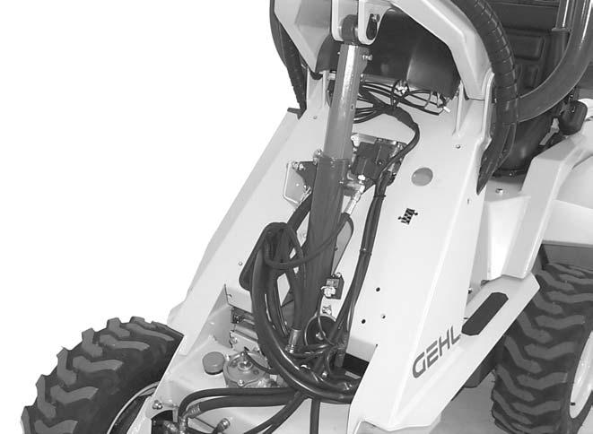
3.ARTICULATION JOINT
This part of the loader connects the front and back frame. The loader is steered hydraulically by the steering cylinder which is mounted between the front and back frames. Hydraulic hoses, electric wires, parking brake wire and drive cable are conducted through the articulation joint
4.LOADER BOOM
This part of the loader is mounted on the front frame with two pivot pins. The attachment coupling plate is mounted on the lower end of the boom. The telescopic boom (standard) extends 20 inches (500 mm) hydraulically.
5.ATTACHMENT COUPLING PLATE
Attachments are mounted on the attachment coupling plate.
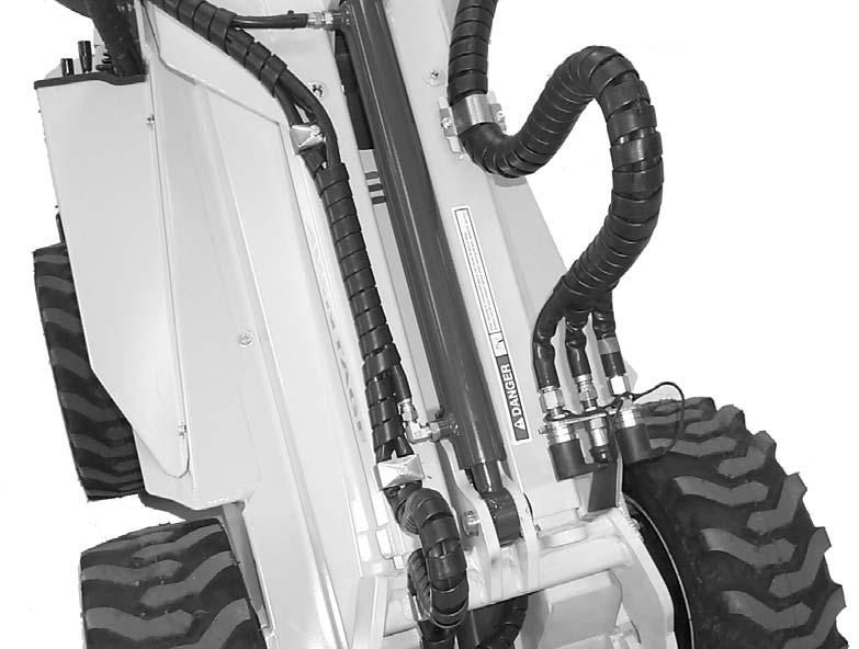
6.AUXILIARY HYDRAULICS OUTLET
The hydraulic hoses of hydraulically operated attachments are mounted on this outlet with quick couplers. The outlet is double acting: it has two pressure lines and one return line.