16 minute read
CHAPTER 9 SERVICE

from Gehl AL20DX Series II Articulated Compact Utility Loader Operator's Manual 918024 - PDF DOWNLOAD
General Information Caution
BEFORE servicing the loader, unless expressly instructed to the contrary, exercise the MANDATORY SAFETY SHUTDOWN PROCEDURE (page 8). After service has been performed, BE SURE to restore all guards, shields and covers to their original positions BEFORE resuming loader operation.
IMPORTANT: Whenever service is performed on hydraulic components, (valves, cylinders, hoses, etc.) transmissions or engines care must be taken to prevent discharging fluids onto the ground. Catch and dispose of fluids per local waste disposal regulations.
This Service chapter details procedures to follow for making routine maintenance checks, adjustments and replacements. For engine related adjustments and servicing procedures, BE SURE to refer to the separate Engine Operator’s Manual provided.
Dealer Services
The following areas of internal components service, replacement and operating adjustments should only be performed (or under the direction of) an authorized GEHL dealer.
Hydraulic Components
The hydraulic pumps are coupled directly to each other (in tandem) and to the engine crankshaft. All service routines related to the internal components of the pumps are precise and critical to proper operation. The hydraulic drive motors are complex devices that require special know-how and tools for servicing.
NOTE: If a hydraulic pump or drive motor is suspected of faulty operation, contact your GEHL dealer for further information and directives.
Valves
Internal component service on any of the hydraulic valves should only be performed by (or under the direction of) an authorized GEHL dealer.
Access to the hydraulic valves is gained by unbolting the access covers. After the hydraulic connections and mechanical linkages are carefully marked and removed, remove the valve and take it to your dealer for service or replacement.
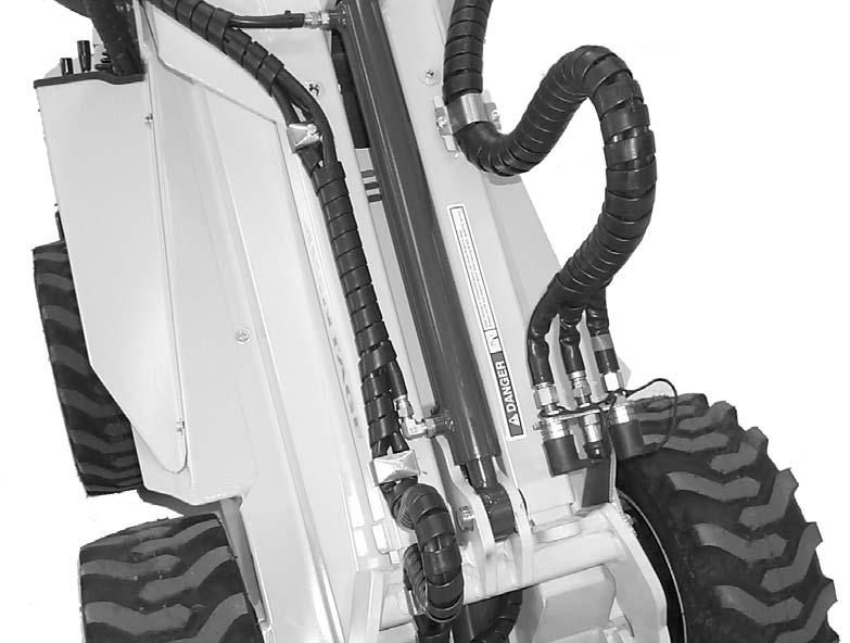
Cylinders
All hydraulic cylinders used on the loader are appropriately designed with particular strokes, diameters and hose connection provisions unique to the loader application requirements. In addition, internal cylinder component service and replacement requires special know-how and tools.
Any of the hydraulic cylinders can be removed from the loader and taken to the dealer for service or replacement. To remove a cylinder from the loader, proceed as follows:
1.Be sure that the lift arm is lowered and in contact with the loader frame.
2.Exercise the MANDATORY SAFETY SHUTDOWN PROCEDURE (page 8)
3.Relieve ALL pressure in the lines by moving the drive and lift/tilt controls in all directions.
4.Disconnect the hydraulic hose connections at the desired cylinder.
5.Remove the rod-end anchor pin first.
6.Lastly, remove the cylinder-end anchor pin. Cylinder replacement is in reverse order of removal.
Operator Services
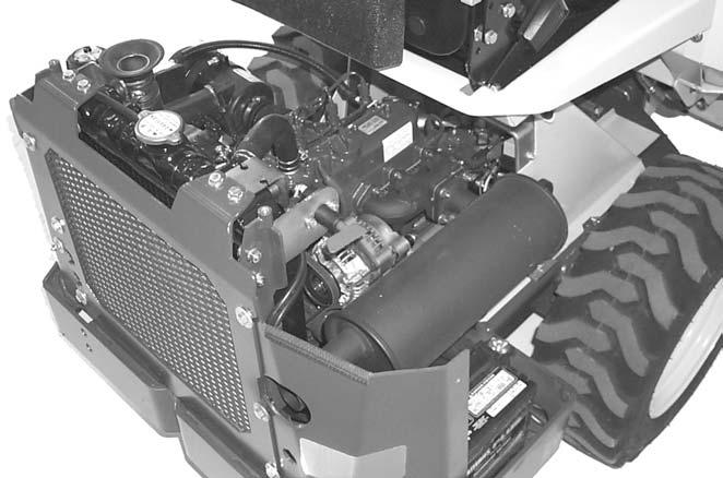
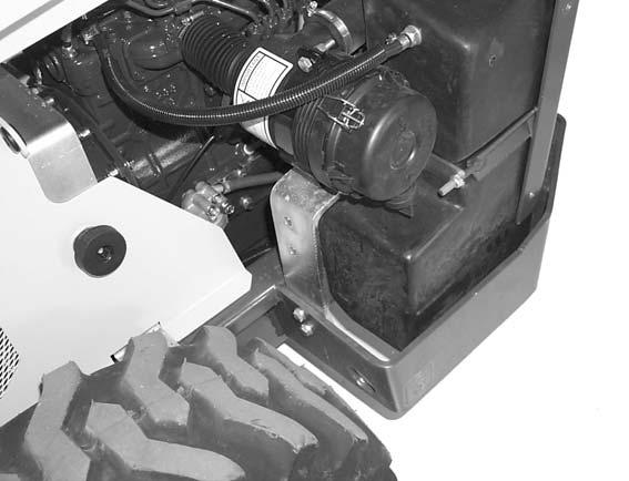
Check Engine Oil Level (Fig. 24)
Unlatch and remove the engine access cover. Pull out the dipstick, located on the left side of engine, and check the oil level. Markings on the dipstick represent both full and low (add oil) levels. Refer to the separate Engine Operator’s Manual for the proper location and procedures for adding/changing engine oil. Also, refer to the separate Engine Operator’s Manual for oil requirements information. A hole in the loader bellyplate gives access to the engine oil drain.
Check Radiator Coolant Level (Fig. 25)
Access to the radiator is obtained by unlatching and removing the engine access cover. Refer to the engine manual for anti-freeze recommendations.
A loader’s engine coolant level is checked and filled by removing the radiator cap. Fluid level should be just below the neck of the filler hole. ALWAYS check the fluid level when the engine is cool.
Warning
DO NOT remove the radiator cap when the engine is HOT or overheated. Coolant is extremely HOT and under pressure and it can burn your skin. Wait for the engine to cool BEFORE relieving the pressure and removing the radiator cap.
Check Engine Air Cleaner (Fig. 25)
Loaders require a daily check of the air cleaner outlet hose and clamps and the mounting bracket hardware to ensure they are secure. The air filter should be changed every 100 hours of operation.
Check Hydraulic Oil Level
The loader is provided with a dipstick on the hydraulic reservoir cap. Markings on the dipstick represent both full and low (add oil) levels. Refer to the Lubrication chapter for oil recommendations. The hydraulic oil should be changed every 500 hours (or one year). Refer to details in the Lubrication chapter.
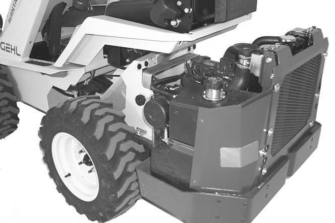
Tighten Wheel Lug Nuts (Fig. 25)
Wheel lug nut torque should be checked after every 50 hours of operation. Tighten the lug nuts, which secure the wheels to the loader axles, to a torque of 70 ft-lbs (95 Nm).
Lubrication
Perform lubrication procedures as detailed in the Lubrication chapter.
Check Alternator/Fan Belt Tension & Condition
Refer to the separate engine manual for setting proper belt tension. If the belt is worn, cracked or otherwise deteriorated, replace the belt following the procedure in the separate engine manual.
Check Battery Electrolyte Level
The battery furnished on the loader is a 12-volt, wet-cell battery. The top of the battery MUST always be kept clean. Clean the battery with a brush dipped in an alkaline solution (ammonia or baking soda and water). After the foaming has stopped, flush the top of the battery with clean water. If the terminals and cable connection clamps are corroded or have a build-up, disconnect the cables and clean the terminals and clamps with the same alkaline solution.
Handling Battery Safely WARNING
Explosive gas is produced while a battery is in use or being charged. Keep flames or sparks away from the battery area. Make sure battery is charged in a well-ventilated area.
NEVER lay a metal object on top of a Battery as a short circuit can result.
Battery acid is harmful on contact with skin or fabrics. If acid spills, follow these first aid tips:
1.IMMEDIATELY remove any clothing on which acid spills.
2.If acid contacts the skin, rinse the affected area with running water for 10 to 15 minutes.
3.If acid contacts the eyes, flood the eyes with running water for 10 or 15 minutes. See a doctor at once. NEVER use any medication or eye drops unless prescribed by the doctor.
4.To neutralize acid spilled on the floor, use one of the following mixtures: a.1 Pound (0.5 kg) of baking soda in 1 U.S. Gallon (4 liters) of water b.1 Pint (0.4 liters) of household ammonia in 1 U.S. Gallon (4 liters) of water
5.Acid from the battery can damage the paint and metal surfaces of the machine. Avoid overfilling the battery cells.
Whenever battery is removed from the unit, BE SURE to disconnect the negative (-) battery terminal connection cable first.
Jump-starting
If the loader battery becomes discharged or does not have enough power to start the engine, use jumper cables and the following procedure to jump-start the loader engine.
Warning
The ONLY safe method for jump-starting a discharged battery is for TWO PEOPLE to carry-out the following process. The second person is needed for removing the jumper cables so that the operator does not have to leave the operator’s compartment while the engine is running. NEVER attempt to make the jumper cable connections directly to the starter solenoid of either engine. DO NOT start the engine from any position other than the operator’s seat and then ONLY after making sure ALL controls are in “neutral.”
Closely follow the procedure, in the order listed, to avoid personal injury. In addition, wear safety glasses to protect your eyes and avoid leaning over the batteries while jump-starting.
DO NOT attempt to jump-start the loader battery if it is frozen, because this may cause it to rupture or explode.
NOTE: BE SURE that the jumper battery is also a 12-volt D.C. battery.
1.Turn the keyswitches of both vehicles to OFF and make sure that both vehicles are in “Neutral” and NOT touching each other.
2.Connect one end of the positive (+) jumper cable to the positive (+) battery terminal on the disabled loader first. DO NOT allow the jumper’s positive cable clamps to touch any metal other than the positive (+) battery terminals. Connect the other end of the positive jumper cable to the jumper battery positive (+) terminal.
3.Connect one end of the negative (-) jumper cable to the jumper battery negative (-) terminal.
4.Make the final negative (-) jumper cable connection to the disabled loader’s engine block or loader frame (ground) -- NOT to the disabled battery’s negative post. If making the connection to the engine, keep the jumper clamp away from the battery, fuel lines or moving parts.
NOTE: Twist jumper cable clamps on the battery terminals and ground connection to ensure a good electrical path for conducting current.
5.Proceed to start the loader. If it does not start immediately, start the jumper vehicle engine to avoid excessive drain on the booster battery.
6.After loader is started and running smoothly, have second person remove the jumper cables (negative (-) jumper cable first) from jumper vehicle battery and then from disabled loader, while making sure not to short the two cables together.
Allow sufficient time for the loader alternator to build up a charge in the battery before attempting to operate the loader or shut off the engine.
Check Tire Pressures
Check the tire pressures after every 50 hours of operation. Tires should be inflated according to the following chart.
Warning
Tire mounting, repairing and replacing should ONLY be performed by a qualified tire manufacturer’s representative, or by properly trained personnel following the tire manufacturer’s instructions. If you do not have such instructions, contact your tire dealer or our Company.
Warning
Inflating or servicing tires can be dangerous. Whenever possible, trained personnel should be called to service and mount tires. To avoid possible death or serious injury, follow the safety precautions below:
• BE SURE the rim is clean and free of rust.
• Lubricate both the tire beads and rim flanges with a soap solution. DO NOT use oil or grease.
• Use a clip-on tire chuck with a remote hose and gauge, which allows you to stand clear of the tire while inflating it.
• DO NOT place your fingers on the tire bead or rim during inflation.
• NEVER inflate beyond 35 PSI (240 kPa) to seat the beads. If the beads have not seated by the time the pressure reaches 35 PSI, deflate the assembly, reposition the tire on the rim, relubricate both parts and re-inflate it. Inflation pressures beyond 35 PSI with unseated beads may break the bead or rim with explosive force sufficient to cause death or serious injury.
• After seating the beads, adjust the inflation pressure to the recommended operating pressure listed.
• DO NOT weld, braze, or otherwise attempt to repair or use a damaged rim.
Tire Inflation Pressures
Proper tire pressure should be maintained equally for all four tires to enhance operating stability and extend tire life. Refer to the chart for the proper inflation pressure. When installing tires on the loader, BE SURE that the tires are of the same size and style on the same side of the loader. ALWAYS replace tires with the same size furnished as original equipment; replacement tires MUST be purchased locally.
Check Radiator Hoses and Clamps
Check for coolant leaks and/or deteriorated hoses.
Oil and Tighten All Linkage Ball Joints
Ball joint style pivoting connectors may used for coupling some controls. The metal to metal type ball joints should be lubricated with a couple of drops of oil to help maintain freedom of movement. At the same time the ball joints are lubricated, all linkage locking nuts should be tightened.
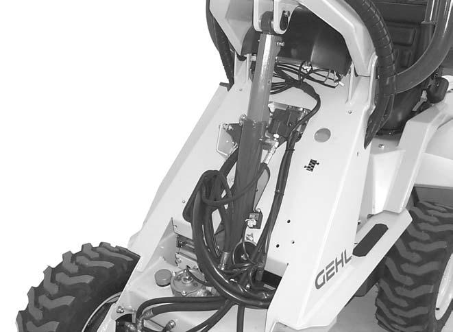
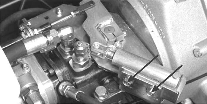
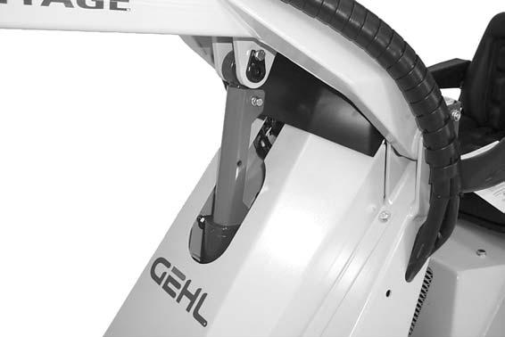
DRIVE CONTROL CABLE (Fig. 26)
The drive control cable needs to be centered after the dable has been replaced. The cable centering is adjusted from the plate located on top of the variable displacement pump. Loosen the bolts marked with the black arrows, gently tap the spring holder cylinder of the centering mechanism until the machine does not move. Afterwards, tighten up the bolts. (It is recommended that this work is performed by an experienced technician).
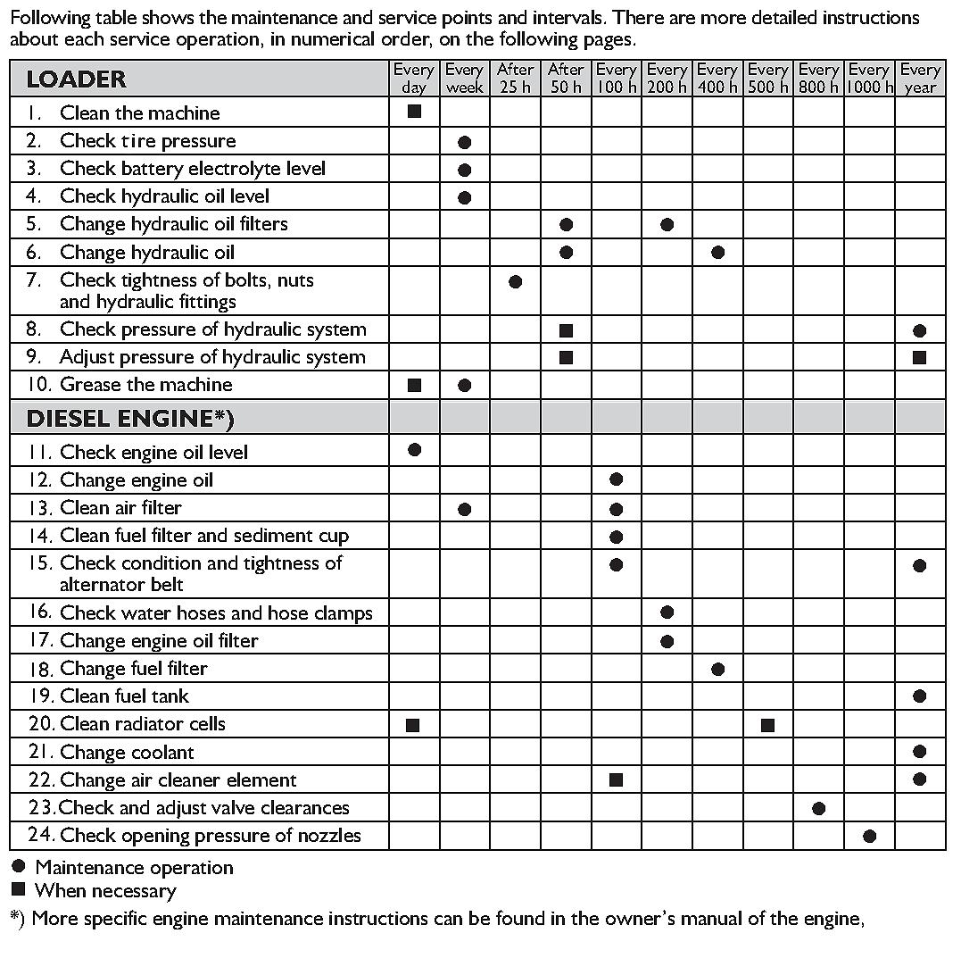
Maintenance Schedule
Chapter 10 Troubleshooting
NOTE: This Troubleshooting guide presents problems, causes and suggested remedies beyond the extent of loose, worn or missing parts. It was developed with the understanding that the machine is in otherwise good operating condition. Refer to the Index at the back of this manual for chapter and topic page references. For additional assistance, contact your GEHL dealer.
Electrical System
Problem Cause Remedy
Starter will not crank. Main fuse is blown. Replace fuse. If it blows again, contact dealer for assistance.
Battery connections are loose or corroded or starter solenoid is defective.
Battery will not recharge.
Entire electrical system does not function.
Indicator lights do not work.
Engine will not turn over.
Engine turns over but will not start.
Clean battery terminals and cables and retighten them or replace solenoid. Check wiring connections.
Electrolyte level is low. Add distilled water to replenish electrolyte.
Terminals or cables are loose or corroded, battery is defective or alternator (or regulator) is defective.
Clean battery terminals and cables and retighten them. If required, have battery tested and/or contact your dealer for testing alternator output, if necessary.
Main fuse is blown. Replace fuse. If it blows again, contact dealer for assistance.
15 ampere fuse is blown. Replace fuse. If it blows again, contact dealer for assistance.
ENGINE (See also separate Engine Manual)
Battery terminals or cables are loose or corroded.
Clean battery terminals and cables and tightly secure them.
Battery is discharged or defective. Recharge battery (refer to battery topic in Service chapter) or replace it.
Starter or pinion is faulty. Contact dealer for directives.
Keyswitch wire connections are loose, broken or disconnected.
Inspect wiring for poor connections or broken leads and repair wiring or connections, as necessary.
Battery is weak or drained. Check battery charge; if battery does not hold a charge, replace it.
Engine cranking speed is too slow. Battery requires recharging or, in cold temperatures, pre-warm engine and hydraulic oils.
Fuel tank is empty. Refill fuel tank; check for faulty fuel gauge.
Fuel shutoff solenoid is not energizing pump.
Check electrical connections to and voltage at fuel shutoff solenoid.
Fuel pump is not working. Refer to Engine Manual or contact your nearest Engine Service center.
Auxiliary hydraulics control lever is in locking position. Turn the lever in center (neutral) position.
ENGINE (Continued)
Problem Cause Remedy
Engine overheats. Crankcase oil is low or too full. Add or remove oil, as required. Engine is overloaded. Operate at half to full throttle. Coolant level is too low. Add coolant, as necessary.
Fan air circulation is restricted by a plugged radiator. With engine off, safely remove restriction.
Exhaust is restricted. Allow exhaust system to cool and then remove restriction.
Engine oil is of the improper grade or is excessively dirty.
Drain and replace oil with proper grade.
Air cleaner filter is restricted. Replace filter.
The machine moves after parking brake has been engaged.
The pins of the parking brake mechanism have not locked properly in the wheels.
Hydrostatic Drive
Drive slowly forward or backward in order to lock the parking brake. When releasing the parking brake, do this in the opposite order.
Problem Cause Remedy
Traction system overloaded. Improve efficiency of operation. overheating.
Hydrostatic drive overheating
Lift and tilt system overloaded. Improve efficiency of operation.
Internal pump or motor leakage. Repair or replace pump or motors; contact dealer for assistance.
Unit being operated in high temperature area with little or no air circulation.
Reduce duty cycle and improve air circulation.
NO response from either the Drive or Lift/Tilt systems.
Hydraulic oil is too heavy. Allow longer warm-up or replace existing oil with proper oil.
Oil supply is too low. Check for low oil level in reservoir. Add oil, as necessary.
Reservoir strainer is plugged. Remove reservoir cover and clean strainer. Also, inspect reservoir for any debris plugging the system.
Wheels turn with servo in neutral.
Neutral centering spring mechanism needs adjustment. Contact dealer for assistance.
Traction drive will not operate in either
Hand brake on.
Disengage hand brake. direction. Oil supply is too low. Check for low oil level in reservoir. Add oil, as necessary.
Control linkage disconnected. Check linkage connection. Reconnect linkage, if necessary. Contact dealer for adjustment assistance.
Low or no drive pump charge pressure. Contact dealer for assistance.
Gear pump not pumping oil. Contact dealer for assistance.
HYDROSTATIC DRIVE (continued)
Problem Cause Remedy
Hydrostatic (drive) system is noisy.
Oil is too heavy. Allow longer warm-up. Replace existing oil with proper weight oil.
Air in system. Check for low oil level in reservoir.
Loose connection to charge inlet. Contact dealer for assistance.
Internal pump or motor damage. Contact dealer for assistance. Neutral is difficult to maintain. Control linkage out of adjustment. Contact dealer for assistance.
Sluggish response to acceleration. Air in system. Check for low oil in reservoir. Add oil, as necessary
Internal motor or pump damage. Contact dealer for assistance.
Engine not responding to load. Troubleshoot/adjust engine per Engine Manual; contact dealer for assistance.
HYDRAULIC CYLINDERS & CONTROLS
NO response to lift arm or bucket.
Lift arm does not raise but bucket operates properly.
Hydraulic cylinder action is slow.
Tilt cylinder leaks down.
Hydraulic attachment does not work when the auxiliary hydraulics control lever is moved.
Gear pump is damaged. Contact dealer for assistance.
Oil flow to pump blocked. Inspect suction hose and reservoir.
Valve not actuated or is leaking. Check connection to valve. Contact dealer for assistance as necessary.
System pump is worn and pressure is low.
Oil is leaking past the cylinder packing or the system valve spool is leaking.
Attachment hoses are not coupled or they are coupled wrongly in the quick couplers.
Check pressure and oil flow. Contact dealer for assistance as necessary.
Contact dealer for assistance.
Make sure that the hoses are properly connected into the quick couplers, change the place of the hoses if necessary. Auxiliary hydraulics have double acting pressure couplers (female) and a return line (male coupler). Operating direction of the attachment depends on how the hoses are connected in the quick couplers.
Attachment hoses will not go into the quick couplers of the machine
Faulty or damaged quick couplers (will restrict or stop oil flow)
There is back pressure in the auxiliary hydraulics line.
Replace quick couplers.
Release the pressure by moving the auxiliary hydraulics control lever in both directions.
Chapter 11 Decal Locations
General Information
Decal location information is provided to assist in the proper selection and application of new decals, in the event the original decals become damaged or the machine is repainted. Refer to the listing for the illustration reference number, part number, description and quantity of each decal provided in the kit. Refer to the appropriate illustrations for replacement locations. To insure proper selection of the correct replacement decals, compare all of the various closeup location drawings to your machine before starting to refinish the unit. Then circle each shown decal (applicable to your machine) while checking off its part number in the listing. After you have verified all the decals needed for replacement, place any extra unnecessary decals aside for disposal.
NOTE: Refer to the SAFETY Chapter of the Operator’s Manual for the specific information provided on all of the various safety decals furnished in the decal kit(s).
New Decal Application
Surfaces MUST be free from dirt, dust, grease and other foreign material before applying the new decal. To apply, remove the smaller portion of the decal backing paper and apply this part of the exposed adhesive backing to the clean surface while maintaining proper position and alignment. Peel the other portion of the backing paper off slowly while applying hand pressure to smooth out the decal surface.
Caution
ALWAYS follow safety precautions on decals. Replace the decals if they are damaged, or if the unit is repainted. If repainting, BE SURE all applicable decals are affixed to your unit.
Paint Notice
Use this list to order paint for refinishing:
906213One Gal. Construction Yellow
906323One Qt. Charcoal Grey
906317One Gal. Charcoal Grey
9062146 (12 oz. Spray Cans) Yellow
9063186 (12 oz. Spray Cans) Grey
The decal kit number for the AL20DX Series II Loader is 140544. The kit includes the following:
Ref.Part
No.No.Description & Quantity
1093476WARNING - Fasten Seat Belt
2122718WARNING - Attachment Lock Pin
3137545Red Reflector (2 Places)
4137628WARNING - Avoid Injury or Death
5137637DANGER - Lift Arm Lock
6137639WARNING - Avoid Injury or Death
7137657WARNING - Avoid Injury or Death
8137660IMPORTANT - Do Not Use Ether When Starting
9137661Tiedown Location (4 Places)
10137842Read Operator’s Manual (pictorial)
11140513AL20DX SERIES II (2 Places)
12155724GEHL (4 Places)
13155729 AVANTAGE (2 Places)
14156139Control Panel
15156306WARNING - Personal Injury Hazard
Chapter 12 Maintenance Log
SERVICE EVERY 10 HOURS
COMPONENT and SERVICE REQUIRED
PROCEDURE and/or CHAPTER TOPIC REFERENCE (Check Page No. in Index)
Check engine oil and radiator coolant level. Refer to Service chapter.
Lubricate grease fittings. Refer to Lubrication chapter.
Check air cleaner and hydraulic fluid level. Refer to Service chapter.
SERVICE EVERY 50 HOURS
Check tire pressure and wheel nut torque. Refer to Service chapter.
Date of Service
SERVICE EVERY 100 HOURS
COMPONENT and SERVICE REQUIRED
PROCEDURE and/or CHAPTER TOPIC REFERENCE (Check Page No. in Index)
Change engine oil and filter. Refer to Engine Operator’s manual.
Check alternator belt tension. Refer to Engine Operator’s manual.
Clean air filter. Refer to Engine Operator’s manual.
Change fuel filter and clean sediment bowl. Refer to Engine Operator’s manual.
Date of Service
Service Every 500 Hours
Change engine coolant. Refer to Engine Owner’s manual.
Change hydraulic fluid. Refer to Service chapter.
Date of Service
Adjustments, 31
Air Cleaner, service check, 35
Alternator Belt, service, 35
Attachment Mountings, 19
Attachments, changing, 23
Auxiliary 12-v DC outlet, 18
Auxiliary Hydraulics, 20
Battery Indicator, 18
Servicing, 35–38
Jump-starting, 36
Battery Switch, 17
Buckets, operating techniques, 27–29
Capacities, 3
Checklists, delivery, 5–7
Controls & Safety Equipment, 15–20
Cylinders
Lift Arm Support Device, 19
Servicing, 34
Troubleshooting, 41
Dealer, Services, 34
Decal Locations, 42–43
Differential Lock, operation, 16
Directional Control Pedal, operation, 16
Drive Control Cable, Service, 38
Dumping, with a Bucket, 28
Electrical System, troubleshooting, 39
Engine
Adjustments, 31
Oil Pressure Indicator, 18
Starting, 21
Troubleshooting, 39–41
Engine lubrication, 32
Engine Oil, check level, 34
Engine temperature gauge, 18 F
Falling Object Protective Structure (FOPS). See Rollover protective structure
Fan Belt. See Alternator Belt
Fuse Block, 18
Glow Plug, Indicator, 18
Greasing, 32
Guards, 15
Hand Brake. See Parking Brake
Highway Travel, 29
Horn Button, 18
Hourmeter, 18
Hydraulic Fluid Overheat, Indicator, 18
Hydraulic Oil, check level, 35
Hydraulic Pump, servicing, 34
Hydraulic Resevoir, 32
Hydraulic Valves, servicing, 34
Hydrostatic Drive, troubleshooting, 40–43
Identification numbers, 2, 5
Ignition Switch. See Keyswitch
Indicator Lights, 18
Instrument and Control Panel, contents, 18
Introduction, 2
Keyswitch, 18
Leveling, with a Bucket, 29
Lift Arm Support Device. See Cylinders
Lift/Tilt, operation, 16
Linkage Ball Joints, tighten, 37
Loader
Moving, 22
Operation, 26
Practice running, 22
Starting operation, 21
Stopping, 22
Loader tipping capacity chart, 26
Lubrication, 32–33
Maintenance, 44–45
MANDATORY SAFETY SHUTDOWN PROCEDURE, 8
Material Density, 24
Moving materials with a bucket, 24 O
Operation, 21–30
Operator, required services, 34–38
Operator’s Manual, storing, 2
Overhead Guard. See FOPS
Pallet Forks, 29
Parking Brake, operation, 15, 23
Pump Control, operation, 16
Radiator, check coolant, 35
Radiator Hoses and Clamps, check, 37
Rollover protective structure, 17
ROPS. See Rollover protective structure
Safety, 8
Scraping, with a Bucket, 28
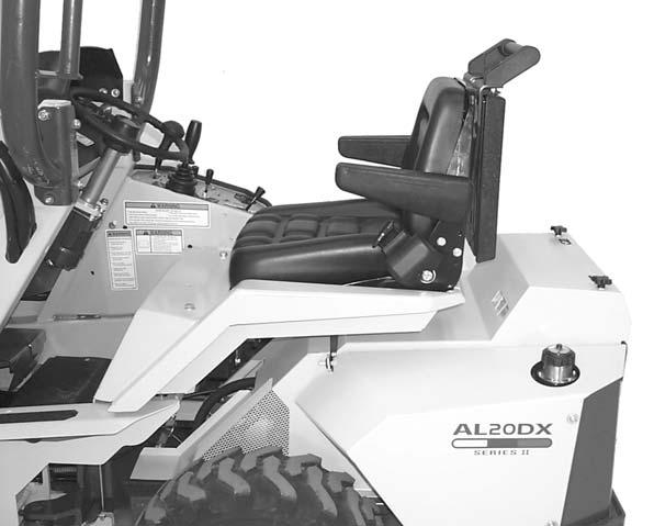
Seat, Operator’s, positioning, 17
Service, 34–38
Shields, 15
Specifications, 3
Starter Switch. See Keyswitch
Tables
Material Densities, 25
Tire Inflation Presures, 37
Telescopic Boom Control, operation, 16
Throttle, operation, 16
Tie-downs, for transporting Loader, 29
Tires, servicing, 37
Transporting Loader, 29
Troubleshooting, 39–41
Warranty, 2
Wheel Lug Bolts, tighten, 35
Torque Specifications
NOTE: Use these torque values when tightening GEHL hardware (excluding: Locknuts and Self-tapping, Thread Forming and Sheet Metal Screws) unless specified otherwise.
All torque values are in Lb-Ft except those marked with an * which are Lb-In (For metric torque value Nm, multiply Lb-Ft value by 1.355 or Lb-In value by 0.113)