ASSEMBLY INSTRUCTIONS DEALER SET-UP INSTRUCTIONS Assembly of this Box Blade is the responsibility of the Frontier dealer. It should be delivered to the owner completely assembled and adjusted for normal conditions. The Box Blade is shipped partially assembled. Assembly will be easier if components are aligned and loosely assembled before tightening hardware. Recommended torque values for hardware are located on page 18.
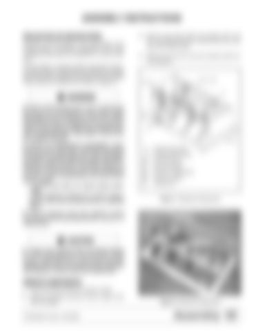
3. Remove cap screws (28), lock washers (27), and hex nuts (26) that secure A-frame bars (6) to the rear of box blade frame. 4. Remove hex nuts (31) and lock washers (30) from mounting pins.
26, 27, 28
30, 31
6
Before dismounting power unit or performing any service or maintenance, follow these steps: disengage power to equipment, lower the 3-point hitch and all raised components to the ground, operate valve levers to release any hydraulic pressure, set parking brake, stop engine, remove key, and unfasten seat belt. NEVER GO UNDERNEATH EQUIPMENT. Never place any part of the body underneath equipment or between moveable parts even when the engine has been turned off. Hydraulic system leak-down, hydraulic system failures, mechanical failures, or movement of control levers can cause equipment to drop or rotate unexpectedly and cause severe injury or death. • Service work does not require going underneath. • Read Operator's Manual for service instructions or have service performed by a qualified dealer.
8
CD6163-2
6. 8. 26. 27. 28. 30. 31.
A-frame bars (set) A-frame support bars 3/4 NC Hex nut 3/4 Lock washer 3/4 NC x 2 Cap screw 7/8 Lock washer 7/8 Hex nut
Figure 7. Shipping Configuration
Keep all persons away from operator control area while performing adjustments, service, or maintenance.
Always wear relatively tight and belted clothing to avoid entanglement in moving parts. Wear sturdy, rough-soled work shoes and protective equipment for eyes, hair, hands, hearing, and head; and respirator or filter mask where appropriate.
REMOVE COMPONENTS 1. Remove banding holding box blade to pallet. 2. Remove lag bolts securing A-frame support bars (8) to the pallet. 5WPMAN0178 (Rev. 4/25/2008)
DP4
Figure 8. Shipping Configuration
Assembly 13


