3 minute read
ASSEMBLY INSTRUCTIONS


DEALER SET-UP INSTRUCTIONS
Assembly of this Box Blade is the responsibility of the Frontier dealer. It should be delivered to the owner completely assembled and adjusted for normal conditions.
The Box Blade is shipped partially assembled. Assembly will be easier if components are aligned and loosely assembled before tightening hardware. Recommended torque values for hardware are located on page18.
Before dismounting power unit or performing any service or maintenance, follow these steps: disengage power to equipment, lower the 3-point hitch and all raised components to the ground, operate valve levers to release any hydraulic pressure, set parking brake, stop engine, remove key, and unfasten seat belt.
NEVER GO UNDERNEATH EQUIPMENT. Never place any part of the body underneath equipment or between moveable parts even when the engine has been turned off. Hydraulic system leak-down, hydraulic system failures, mechanical failures, or movement of control levers can cause equipment to drop or rotate unexpectedly and cause severe injury or death.
•Service work does not require going underneath.
•Read Operator's Manual for service instructions or have service performed by a qualified dealer.
Keep all persons away from operator control area while performing adjustments, service, or maintenance.
3. Remove cap screws (28), lock washers (27), and hex nuts (26) that secure A-frame bars (6) to the rear of box blade frame.
4. Remove hex nuts (31) and lock washers (30) from mounting pins.
Always wear relatively tight and belted clothing to avoid entanglement in moving parts. Wear sturdy, rough-soled work shoes and protective equipment for eyes, hair, hands, hearing, and head; and respirator or filter mask where appropriate.
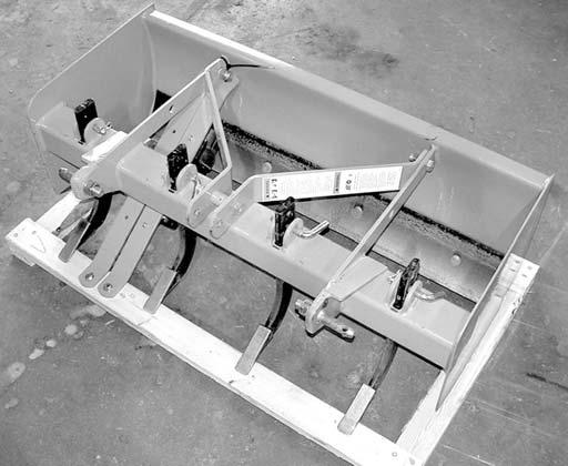
Remove Components
1. Remove banding holding box blade to pallet.
2. Remove lag bolts securing A-frame support bars (8) to the pallet.
Assemble Box Blade
2. Secure with lock washers (30) and hex nuts (31) previously removed from mounting pins.
3. Attach A-frame support bars (8) to the box blade frame and secure with cap screws (28), lock washers (27), and hex nuts (26) previously removed.
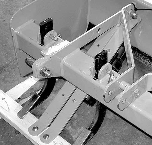
4. Remove cap screw (29), sleeve (7), lock washer (27), and hex nut (26) that secure the A-frame bars together.
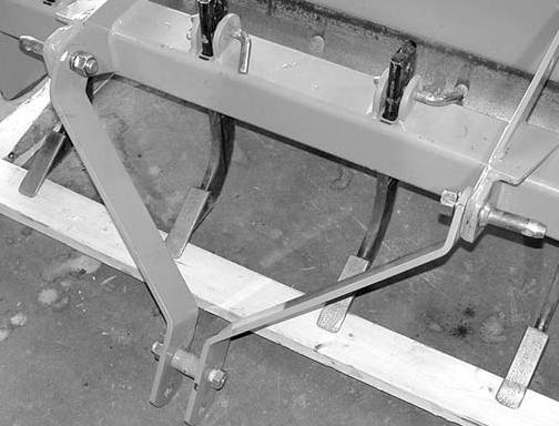
5. Align A-frame support bars with the lower hole on A-frame bars and secure with cap screw, sleeve, lock washer, and hex nut previously removed. NOTE: A-frame support bars must be on the outside of the A-frame bars as show in Figure 12.
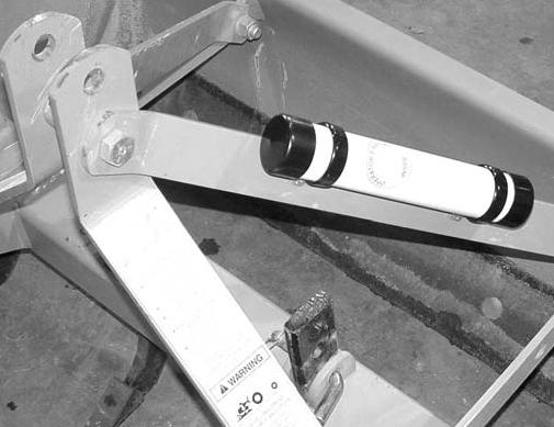
QUICK HITCH BUSHING KIT #5WP1004653 (OPTIONAL)
Install sleeve (1) over lower 3-point pin and secure with Klik pin (2). The sleeve already installed for Category 1 hitch will work for top link.
(Other parts included in kit are not required for this application.)
Dealer Check Lists
PRE-DELIVERY CHECK LIST (DEALER’S RESPONSIBILITY)
Inspect the equipment thoroughly after assembly to ensure it is set up properly before delivering it to the customer.
The following check lists are a reminder of points to inspect. Check off each item as it is found satisfactory or after proper adjustment is made.
___Check that all safety decals are installed and in good condition. Replace if damaged.
___Properly attach implement to tractor and make all necessary adjustments.
___Check all bolts to be sure they are properly torqued.
___Check that all cotter pins and safety pins are properly installed. Replace if damaged.
DELIVERY CHECK LIST (DEALER’S RESPONSIBILITY)
___Show customer how to make adjustments.
___Point out the safety decals. Explain their meaning and the need to keep them in place and in good condition. Emphasize the increased safety hazards when instructions are not followed.
___Present Operator's Manual and request that customer and all operators read it before operating equipment. Point out the manual safety rules, explain their meanings and emphasize the increased safety hazards that exist when safety rules are not followed.
___Explain to customer the potential crushing hazards of going underneath raised equipment. Instruct customer that service work does not require going underneath unit and never to do so.
___Show customer the safe, proper procedures to be used when mounting, dismounting, and storing equipment.
___For mounted units, add wheel weights, ballast in front tires, and/or front tractor weight to enhance front end stability. A minimum 20% of tractor and equipment gross weight must be on front tractor wheels. When adding weight to attain 20% of tractor and equipment weight on front tractor wheels, you must not exceed the ROPS weight certification. Weigh the tractor and equipment. Do not estimate!