22 minute read
Adjustment, Repair and Replacement


Do not add cold coolant to a hot engine. This can cause engine casting damage. Allow the engine to cool to below 50°C (120°F) before adding coolant.
Remove the radiator or fill cap and check the coolant level. Refer to the OEM service manual instructions for recommendations. Add coolant if necessary. Do not overfill.
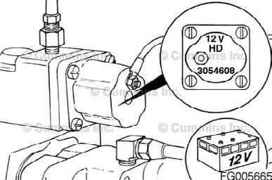
Fuel Shutoff Valve
Voltage Check
CAUTION!
To avoid damage to the ECM, connect only one wire to the fuel shut off solenoid.
Connect the wire. Make sure the shutoff valve coil is the correct voltage. The coil voltage and part number are cast into the terminal connection end of the coil. Turn the vehicle starter switch to the "ON" position. Check the voltage to the coil with a multimeter, Part Number 3377161, or equivalent.The voltage must be the same as the battery voltage.Turn the vehicle starter switch to the "OFF" position. The voltage must be the dame as the battery voltage. Turn the vehicle starter switch to the "OFF" position.
Drive Belt, Alternator
Figure 172
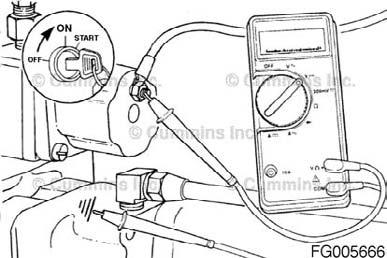
Figure 173
QSM11 Cummins Engine Page 96 QSM11CUMMINSENG
Install
Install a new belt over the pulleys while holding the tensioner back. Be careful not to damage the belt while working it over the flanged pulleys. Release the tensioner, and remove the breaker bar. Belt drive systems equipped with an automatic belt tensioner cannot be adjusted. A belt tension gauge will not give an accurate measure of the belt tension. The automatic belt tensioner is designed to maintain the proper belt tension over the life of the belt. Only inspection of the tensioner is required.
The belt tensioner is designed to operate within the limit of arm movement provided by the cast stops when the belt length and geometry are correct. If the tensioner is hitting either of the limits during operation, check the mounting brackets and belt length. Loose brackets, bracket failure, alternator movement, incorrect belt length, or belt failure can cause the tensioner to hit the limits.
Install a new belt on the water pump and alternator pulleys. To prevent damage, do not roll a belt over the pulley or pry on it with a tool. Turn the adjusting screw (1) clockwise to increase the belt tension. Use belt tension gauge, Part Number ST-1293, or equivalent, to measure the belt tension. Refer to Procedure 018-005 (Drive Belt Tension) in Section V for the correct tension value for the belt is installed. NOTE: A belt is considered used if it has been in operation for ten minutes or longer.
Tighten the adjusting screw locknut (2) against the retainer. Tighten the adjustment link locking cap screw (3). Torque Value: 80 Nm [60ftlb] Tighten the pivot cap screw (4) and nut (5). Torque Value: 47 Nm [35ftlb]
Figure 174


Figure 175
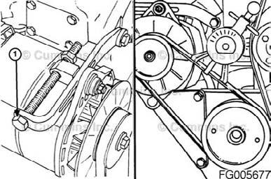
Figure 176

Figure 177
QSM11 Cummins Engine QSM11CUMMINSENG Page 97
Adjust
Adjustment Link Type Loosen the adjusting screw locknut (1) Loosen the adjustment link locking cap screw (2). Loosen the pivot cap screw and nut (3).
Use belt tension gauge, Part Number ST-1293, to measure belt tension. Turn the alternator adjusting screw (1) clockwise to tighten the belt. Refer to Procedure 018-005 (Drive Belt Tension) in Section V. NOTE: A belt is considered used if it has been in operation for ten minutes or longer.
Tighten the adjusting screw locknut (2) against theretainer.Tighten the adjustment link locking cap screw (3). Torque Value: 80 Nm [60ftlb] Tighten the pivot cap screw (4) and nut (5). Torque Value: 47 Nm [35ftlb]
Figure 178


Figure 179
Figure 180
QSM11 Cummins Engine Page 98 QSM11CUMMINSENG
Belt drive systems equipped with an automatic belt tensioner cannot be adjusted. A belt tension gauge will not give an accurate measure of the belt tension. The automatic belt tensioner is designed to maintain proper belt tension over the life of the belt. Only inspection of the tensioner is required. The belt tensioner is designed to operate within the limit of arm movement provided by the cast stops when the belt length and geometry are correct. If the tensioner is hitting either of the limits during operation, check the mounting brackets and the belt length. Loose brackets, bracket failure, alternator movement, incorrect belt length, or belt failure can cause the tensioner to hit the limits. NOTE: If the engine is equipped with a secondary alternator, reference to the vehicle manufacturer for the secondary alternator belt adjustment procedure.

Figure 181
QSM11 Cummins Engine QSM11CUMMINSENG Page 99
General Information
A new automatic tensioning single belt fan and alternator drive is the standard option for the QSM industrial engine. The design uses an eight-rib poly-vee belt with an automatic tensioner and a fixed idler. The belt tensioner is designed to operate within the limit of arm movement provided by the cast stops when the belt length and geometry are correct. If the tensioner is hitting either of the limits during operation, check the mounting brackets and the belt length. Loose brackets, bracket failure, alternator movement, incorrect belt length, or belt failure can cause the tensioner to hit the limits.
Remove
Remove the mounting cap screws and the belt tensioner from the bracket.
Use a ¾-inch drive breaker bar to hold back the tensioner and relieve the belt tension. Rotate the tensioner away from the belt until it stops. Remove the alternator belt while holding the tensioner back.
Figure 182

Figure 183

Figure 184
QSM11 Cummins Engine Page 100 QSM11CUMMINSENG
Install
Install the belt tensioner. Install and tighten cap screws. Torque Value: 47 Nm [35ftlb]
Tighten the tensioner mounting cap screw. Torque Value: 47 Nm [35ftlb]
Install the alternator belt over the pulleys while holding the tensioner back with a ¾-inch drive breaker bar. Use care in working belt over the edge of flanged pulleys. Release the tensioner and remove the breaker bar. The belt tensioner is designed to operate well within the limit of arm movement, provided by the cast stops, when the belt length and geometry are correct.
QSM11 Cummins Engine Figure 185

Figure 186
Figure 187
Figure 188
QSM11CUMMINSENG Page 101
Remove
Remove the dust seal. Remove the five water pump oil seal cap screws, clamping ring, oil seal, and gasket. Remove the dust seal as the seal carrier is removed; or use a heel bar, or similar tool, to pry the dust seal away from the seal case. Then remove the dust seal by hand. Discard the oil seal and dust seal.
The coolant flow that provides cooling to the torque converter (if equipped) is achieved in different manners. ISM and QSM Series engines use a torque converter cooler disk inside the coolant bypass hose to direct engine coolant to the inlet side of the torque converter cooler. 1. Torque converter coolant supply 2. Torque converter disk (orifice) 3. Bypass hose 4. Water pump
Loosen the EGR cooler coolant supply lower tube retaining clamp cap screw. Remove the EGR cooler coolant supply lower tube retaining clamp and tube. Remove and discard the O-ring.
Figure 189


Figure 190
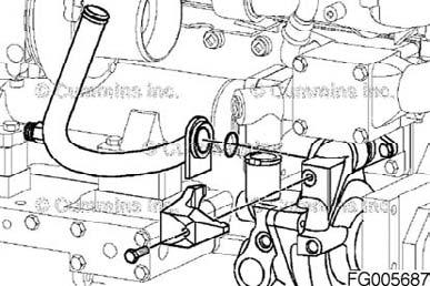
Figure 191
QSM11 Cummins Engine Page 102 QSM11CUMMINSENG
Remove the three water pump mounting cap screws. Remove the two water pump water transfer connection cap screws and push the water pump transfer connection into the water pump as far as possible to facilitate water pump removal. Remove the water pump. Twist the pump outward from the top, and angle the rear of the pump downward as it is being removed to allow the pump to pass the thermostat housing support. Remove the water pump water transfer connection from the water pump.
Check the needle bearing for damage and freedom of needle rotation. Replace the bearing if it is damaged or if it does not turn freely. If the bearing is replaced, use bearing installation tool, Part Number 3824117, along with a cup driver to remove the needle bearing from the gear housing. Gently tap the bearing out from the rear side of the housing.
Remove the pressure cap when the engine is cool.
Drain the cooling system. Refer to Procedure 008-018 (Cooling System) in Section 7.
WARNING!
Do not remove the pressure cap from a hot engine. Wait until the coolant temperature is below 50°C (120°F) before removing the pressure cap. Heated coolant spray or steam can cause personal injury.
WARNING!
Coolant is toxic. Keep away from children and pets. If not reused, dispose of in accordance with local environmental regulations. Figure 192

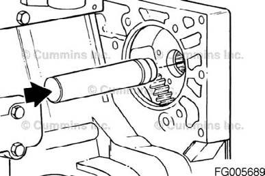
Figure 193

Figure 194

Figure 195
QSM11 Cummins Engine QSM11CUMMINSENG Page 103
NOTE: Be sure the puller cap screws are threaded all the way through the puller before applying pressure to the puller screw. Remove the alternator drive belt. Refer to Procedure 013°©005 (Drive Belt, Alternator) in Section A. Remove the water pump pulley retaining cap screw. Use the standard pulley puller, Part Number ST-647, or equivalent, and two 5/16x18x2 cap screws to remove the pulley.
Remove the alternator. Refer to a Cummins Authorized Repair Location.
NOTE: Remove the dust seal as the seal carrier is removed, or use a heel bar, or similar tool, to pry the dust seal away from the seal case. Then remove the dust seal by hand. Remove the dust seal. Remove the five water pump oil seal cap screws, clamping ring, oil seal, and gasket. Discard the oil seal and dust seal.
Loosen the coolant bypass hose clamps on both the upper and lower hoses. Remove the upper coolant hose from the thermostat housing.
Figure 196
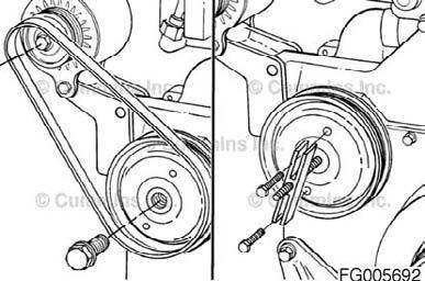

Figure 197
Figure 198

Figure 199
QSM11 Cummins Engine Page 104 QSM11CUMMINSENG
The coolant flow that provides cooling to the torque converter (if equipped) is achieved in different manners. ISM and QSM Series engines use a torque converter cooler disk inside the coolant bypass hose to direct engine coolant to the inlet side of the torque converter cooler. 1. Torque converter coolant supply. 2. Torque converter disk (orifice). 3. Bypass hose. 4. Water pump.
Remove the two water pump water transfer connection cap screws. Remove the three water pump mounting cap screws. Rotate the water pump outward so the water transfer connection can be removed from the water pump. Remove the water transfer connection from the water pump.
Remove the water pump. Twist the pump outward from the top, and angle the rear of the pump downward as it is being removed to allow the pump to pass the thermostat housing support.
Figure 200

Figure 201

Figure 202
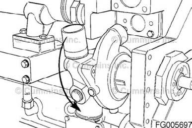
Figure 203
QSM11 Cummins Engine QSM11CUMMINSENG Page 105
Install
If the needle bearing was removed, use bearing installation tool, Part Number 3824117, to install a new needle bearing in the gear housing. The bearing must be installed with the part number side of the bearing against the installation tool to prevent damage to the bearing during the installation. Install the bearing from the front side of the gear housing until the bearing is flush with the front edge of the housing bore.
Install the water pump cover. Use a new O-ring seal. Torque Value: 47 Nm [35ftlb] Install the water pump water transfer connection into the water pump. Install a new O-ring on the water pump mounting flange. The water pump must be twisted outward from the top until the transfer outlet clears the thermostat housing support during installation Install the water pump. Twist the water pump inward and install the three water pump mounting cap screws. Torque Value: 47 Nm [35ftlb] Install a new gasket on the water pump water transfer connection. Install and tighten the water transfer connection cap screws. Torque Value: 25 Nm [18ftlb]
CAUTION!
To reduce the possibility of pinching or rolling the O-rings during assembly do not lubricate the O-rings. Lubricate the O-ring connection mating surface with clean engine coolant, soapy water, or vegetable oil. Figure 204


Figure 205

Figure 206
QSM11 Cummins Engine Page 106 QSM11CUMMINSENG
If the engine is equipped with a torque converter cooler, install the disk in the bypass hose before installing the thermostat housing. 1. Torque converter coolant supply 2. Torque converter disk (orifice) 3. Bypass hose 4. Water pump.
Install a new O-ring on the EGR cooler coolant supply lower tube. Insert the EGR cooler coolant supply lower tube into the water pump body. Install the EGR cooler coolant supply lower tube is seated completely in the water pump body before tightening the EGR cooler coolant supply lower tube retaining clamp cap screw to reduce the possibility of pinching the O-ring. Tighten the cap screw. Torque Value: 34 Nm [25ftlb] The oil seal must be installed with the lip of the seal and the shaft clean and dry. Do not lubricate. The yellow dust lip must be facing out. Install the new gasket and oil seal. Use the installation sleeve provided with the new seal to install the seal. The cap screw threads must be coated with thread sealant, Part Number 3823494, or equivalent, to prevent oil leakage. Torque Value: Step1 7 Nm [60inlb] Step2 20 Nm [180inlb]
CAUTION!
To reduce the possibility of pinching or rolling the O-rings during assembly do not lubricate the O-rings. Lubricate the O-ring connection mating surface with clean engine coolant, soapy water, or vegetable oil. Figure 207

Figure 208

Figure 209
QSM11 Cummins Engine QSM11CUMMINSENG Page 107
Place a light film of oil or antifreeze on the inside of the oil seal dust seal. Install the dust seal onto the shaft with a larger outside surface facing the engine. Push the dust seal back by hand on the shaft until the entire dust seal contacts the oil seal case.
NOTE: The water pump must be twisted outward from the top until the transfer outlet clears the thermostat housing support during installation. Install a new O-ring on the water pump mounting flange. Install the water pump.
Install a new O-ring on the water pump water transfer tube.Install the connection into the water pump. Twist the water pump inward, and install the three water pump mounting cap screws. Torque Value: 47 Nm [35ftlb] Install a new gasket on the water pump water transfer connection. Install and tighten the water transfer connection cap screws. Torque Value: 25 Nm [221inlb]
If the engine is equipped with a torque converter cooler, install the disk in the bypass hose before installing the thermostat housing. 1. Torque converter cooler coolant supply. 2. Torque converter cooler disk (orifice). 3. Bypass hose. 4. Water pump.
Figure 210


Figure 211

Figure 212
Figure 213
QSM11 Cummins Engine Page 108 QSM11CUMMINSENG
Install the thermostat in the housing. Install a new seal in the groove on the thermostat housing mounting surface.
Install the hose on the thermostat housing bypass outlet. Install the thermostat housing and four mounting cap screws. Torque Value: 54 Nm [40ftlb]
Equally space the bypass hose over the water pump connection and thermostat housing connection, and tighten the bypass hose clamps. Torque Value: 3 Nm [27inlb] Install the upper and lower coolant hoses. Refer to the OEM's specifications for the correct torque value.
The oil seal must be installed with the lip of the seal and the shaft clean and dry. Do not lubricate. The yellow dust lip must be facing out. Install the new gasket and oil seal. Use the installation sleeve provided with the new seal to install the seal. The cap screw threads must be coated with thread sealant, Part No. 3823494, or equivalent, to prevent oil leakage. Torque Value: Step1 7 Nm [62inlb] Step2 20 Nm [177inlb]
Figure 214

Figure 215

Figure 216
Figure 217
QSM11 Cummins Engine QSM11CUMMINSENG Page 109
Place a light film of oil or antifreeze on the inside diameter of the dust seal. Install the dust seal onto the shaft with the larger outside diameter facing the engine. Push the dust seal back by hand on the shaft until the entire dust seal contacts the oil seal case.
Use pulley pusher adapter (1), Part Number 3377401, or equivalent, and pulley pusher (2), Part Number 3376326, or equivalent, to install the pulley. Install the cap screw in the shaft. Torque Value: 75 Nm [55ftlb]
Install the alternator. Refer to a Cummins Authorized Repair Location. Install and adjust the alternator drive belt. Refer to 013°©005 (Drive Belt, Alternator) in Section A.
Close the cooling system drain valve, and install the lower coolant hose. Tighten the hose clamps. Refer to the manufacturer's specifications for the correct torque value.
Figure 218

Figure 219

Figure 220

Figure 221
QSM11 Cummins Engine Page 110 QSM11CUMMINSENG
The correct concentration of coolant additives must be used in the cooling system. Refer to Procedure 018-004 (Coolant Recommendation and Specifications) in Section V. Fill the cooling system. Refer to Procedure 008-018 (Cooling System) in Section 7. Operate the engine until it reaches a temperature of 71°C (160°F) and check for coolant leaks.

Figure 222
Coolant Thermostat
Remove
WARNING!
Do not remove the pressure cap from a hot engine. Wait until the coolant temperature is below 50°C (120°F) before removing the coolant system pressure cap. Heated coolant spray or steam can cause personal injury.
Remove the pressure cap when the engine is cool.
Drain the cooling system as follows: • Open the radiator drain valve. • Remove the lower radiator hose.
WARNING!
Coolant is toxic. Keep away from children and pets. If not reused, dispose of in accordance with local environmental regulations. Figure 223
Figure 224
QSM11 Cummins Engine QSM11CUMMINSENG Page 111
Remove the upper coolant hose from the thermostat housing. Loosen the coolant bypass hose clamps. NOTE: Some models could have a converter cooler disk located in the bypass hose.
Remove the four thermostat housing mounting cap screws and the thermostat housing.
Remove the thermostat from the housing.
Install
Install the thermostat in the housing. Install a new O-ring seal in the groove on the thermostat housing mounting surface.
Figure 225
Figure 226
Figure 227
QSM11 Cummins Engine Page 112 Figure 228
QSM11CUMMINSENG
Install the hose on the thermostat housing bypass outlet. Install the thermostat housing and four mounting cap screws. Tighten the mounting cap screws. Torque Value: 54 Nm [40ftlb]
Install the upper coolant hose to the thermostat housing outlet. Torque Value: 3 Nm [30inlb]
Close the cooling system drain valve, and install the lower coolant hose. Tighten the hose clamp. Refer to the OEM's specifications for the correct torque value.
The correct concentration of coolant additives must be used in the cooling system. Refer to Procedure 018-003 (Cummins Recommendations and Specifications) in Section V. Fill the cooling system. Refer to Procedure 008-018 (Cooling System) in Section 7. Operate the engine until it reaches 80°C (180°F), and check for coolant leaks.
Figure 229
Figure 230
Figure 231
Figure 232
QSM11 Cummins Engine QSM11CUMMINSENG Page 113
Remove
Wastegated Remove the four turbocharger mounting nuts. Remove the turbocharger and gasket.

Figure 233
Install
Wastegated NOTE: For wastegated turbochargers, refer to Procedure 010-050 for wastegate actuator installation. Apply a film of anti-seize lubricant, Part Number 3824879, or equivalent, to the turbocharger mounting studs.
Use a new gasket when installing the turbocharger.Install and tighten the four mounting nuts. Torque Value: 61 Nm [45ftlb]
Figure 234
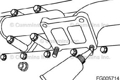

Figure 235
QSM11 Cummins Engine Page 114 QSM11CUMMINSENG
Compare the assembly number (1) on the turbocharger data tag with the turbocharger specified in the engine control parts list (CPL) number (2) listed on the engine data tag.
If the correct turbocharger was not installed, remove it, and install the correct turbocharger.
Refrigerant Compressor Drive
General Information
Industrial Applications A new refrigerant compressor drive system is offered on the QSM11 industrial. The new drive system has an accessory drive pulley, a six-rib poly-vee belt with automatic tensioning and a backside idler for use with a Sanden rotary compressor.
Remove
Industrial Applications Use a 3/8-inch drive breaker bar to hold back the tensioner and relieve the belt tension. Rotate the tensioner away from the belt. Remove the refrigerant drive belt while holding the tensioner back. Relieve the tensioner to neutral position.
QSM11 Cummins Engine Figure 236
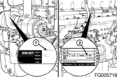

Figure 237

Figure 238
QSM11CUMMINSENG Page 115
Install
Industrial Applications Position the enclosed subassembly (idler pulley) (1) and tensioner mounting bracket (2) on the gear cover and mount with the four cap screws (3) and washers. 1. The tensioner idler pulley will be located in front of two of the mounting cap screw locations in the free state. The tensioner either will have to be removed completely for this process or the arm moved to one side to have access to all four cap screw mounting locations. 2. Install the belt tensioner (4), and tighten the mounting nut. Torque Value: 47 Nm [35ftlb] Tighten the four mounting cap screws. Torque Value: 20 Nm [177inlb] Use a 3/8-inch drive breaker bar to hold back the tensioner. Install the drive belt while holding the tensioner back. Allow the tensioner to rotate against the belt.
Figure 239

Figure 240
Figure 241
QSM11 Cummins Engine Page 116 QSM11CUMMINSENG
Remove
WARNING!
Batteries can emit explosive gases. To reduce the possibility of personal injury, always ventilate the compartment before servicing the batteries. To reduce the possibility of arcing, remove the negative (-) battery cable first, and attach the negative (-) battery cable last.
NOTE: The starting motor mounting cap screws can be metric or standard thread sizes. Make sure to install the same-size cap screws that were removed. Remove the electrical connections from the batteries. Tag and remove the electrical connections from the starting motor.
Remove the three cap screws and the starting motor.
Figure 242
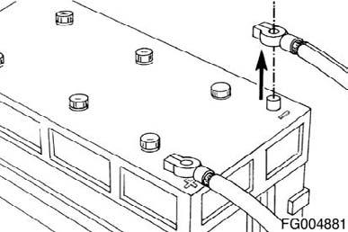

Figure 243
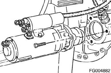
Figure 244
QSM11 Cummins Engine QSM11CUMMINSENG Page 117
Install
screws are the correct size and grade.Install the starting motor and the three mounting cap screws. Tighten the cap screws. Torque Value: 90 Nm [66ftlb]
Install and tighten the electrical connections to the starting motor.
Install and tighten the battery electrical connections.
WARNING!
Batteries can emit explosive gases. To reduce the possibility of personal injury, always ventilate the compartment before servicing the batteries. To reduce the possibility of arcing, remove the negative (-) battery cable first, and attach the negative (-) battery cable last. Figure 245
Figure 246
Figure 247
Engine Storage - Long Term
General Information
If the engine will be out of service longer than 6 months, take special precautions to prevent rust. Contact the nearest Cummins Authorized Repair Location for information concerning engine storage procedures.


