21 minute read
at 1,500 HoursMaintenance Procedures


MAINTENANCE PROCEDURES AT 1,500 HOURS
Maintenance Procedures - Overview
General Information
All maintenance checks and inspections listed in previous maintenance intervals must also be performed now, in addition to those listed under this maintenance interval.
Overhead Set
Adjust
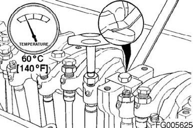
Valves and injectors must be correctly adjusted for the engine to operate efficiently. Valve and injector adjustment must be performed using the values listed in this section. The accompanying table gives the adjustment specifications. If the valves and injectors have been adjusted during troubleshooting or before this scheduled interval, adjustment is not required now.
All valve and injector adjustments must be made when the engine is cold (any stabilized coolant temperature at 60°C (140°F) or below).
Valve, Injector Adjustment Specifications mm in
Intake Valve 0.36 0.014 Exhaust Valve 0.69 0.027
Figure 105
QSM11 Cummins Engine QSM11CUMMINSENG Page 73
The valve set marks are located on the accessory drive pulley. The marks align with a pointer on the gear cover. Use the accessory driveshaft to rotate the crankshaft.
The crankshaft rotation is clockwise when viewed from the front of the engine. The cylinders are numbered from the front gear housing end of the engine. The engine firing order is 1-5-3-6-2-4.
Each cylinder has three rocker levers: • The long rocker lever (E) is the exhaust lever. • The center rocker lever is the injector lever. • The short rocker lever (l) is the intake lever. Refer to the accompanying graphic for valve rocker lever locations.
WARNING!
Do not straighten a bent fan blade or continue to use a damaged fan. A bent or damaged fan blade can fail during operation and cause personal injury or property damage. Figure 106
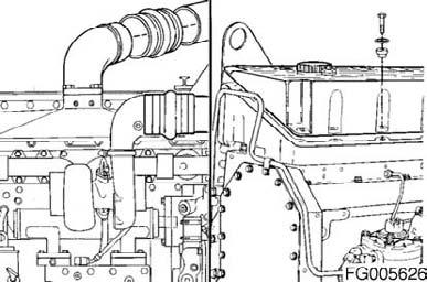

Figure 107
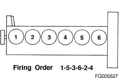
Figure 108

Figure 109
QSM11 Cummins Engine Page 74 QSM11CUMMINSENG
The valves and injectors on the same cylinders are adjusted at the same index mark on the accessory drive pulley. One pair of valves and one injector are adjusted at each pulley index mark before rotating the accessory drive to the next index mark. Two crankshaft revolutions are required to adjust all the valves and injectors. NOTE: See the example before attempting to begin the adjusting procedure. NOTE: Set the injector on the same cylinder before setting valves. .Adjust all the injectors, valves, and brakes (if equipped) to the following injector and valve adjustment sequence chart.
Injector and Valve Measurement Sequence
Bar Engine in Direction of Rotation Pulley Position Set Cylinder Injector Valve
Start A 1 1 Advance to B 5 5 Advance to C 3 3 Advance to A 6 6 Advance to B 2 2 Advance to C 4 4 Firing Order: 1-5-3-6-2-4
The adjustment can begin on any valve set mark. In the following example, the adjustment will begin on the "A" valve set mark with cylinder Number 1 valves closed and ready for adjustment. Rotate the accessory drive clockwise until the "A" valve set mark on the accessory drive pulley is aligned with the pointer on the gear cover.
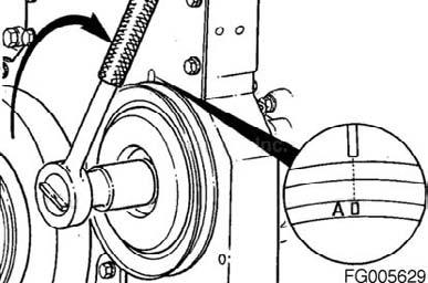
Figure 110
QSM11 Cummins Engine QSM11CUMMINSENG Page 75
When the "A" mark is aligned with the pointer, the intake and exhaust valves for cylinder Number 1 must be closed. If these conditions are not correct, cylinder Number 6 injector and valves must be ready to set. Set the injector and valves on the cylinder so both the intake and exhaust valve rocker lever arms are loose and can be moved from side to side. Both valves are closed when both rocker levers are loose and can be moved from side to side.
Injectors
Loosen the injector adjusting screw locknut. Using a screwdriver (box end wrench if equipped with engine brakes) and the adjusting screw, bottom the injector plunger three or four times to remove the fuel. Turn the adjusting screw in until you can feel it just bottom the plunger. NOTE: Do not use excessive force when bottoming the plunger. Back out the adjusting screw two flats, 120 degrees. Hold the adjusting screw, and tighten the locknut. Torque Value: 61 Nm [45ftlb] After setting the injector, set the valves on the same cylinder.
Figure 111

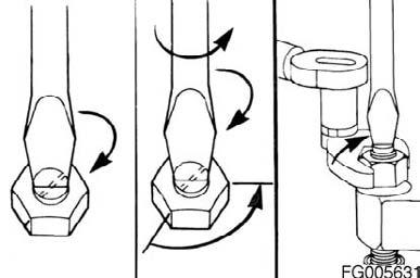
Figure 112

Figure 113
QSM11 Cummins Engine Page 76 QSM11CUMMINSENG
Valves
With the "A" valve set mark aligned with the pointer on the gear cover and both valves closed on the cylinder to be adjusted, loosen the adjusting screw locknuts on the intake and exhaust valves.
Select a feeler gauge for the correct valve lash specification. Valve Lash Specification
Insert the feeler gauge between the top of the crosshead and the rocker lever pad.
Two different methods for establishing valve lash clearance are described below. Either method can be used; however, the torque wrench method has proven to be the most consistent. It eliminates the need to feel the drag on the feeler gauge. • Torque Wrench Method: Use the inch-pound torque wrench, Part Number 3376592, normally used to set preload on top-stop injectors, and tighten the adjusting screw. Torque Value: 0.7 Nm [6inlb] • Touch Method: Tighten the adjusting screw until a slight drag is felt on the feeler gauge.
Hold the adjusting screw in this position. The adjusting screw must not turn when the locknut is tightened. Torque Value: • Without Torque 61 Nm [45ftlb] • Wrench Adapter With Torque 47 Nm [35ftlb] • Wrench Adapter, Part Number 3163196
mm in
Intake 0.36 0.014 Exhaust 0.69 0.027
Figure 114
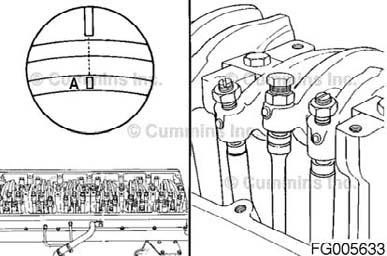
Figure 115
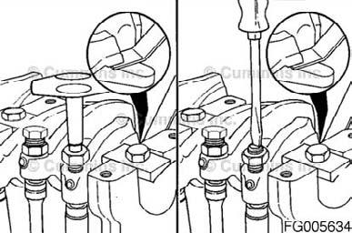
Figure 116

Figure 117
QSM11 Cummins Engine QSM11CUMMINSENG Page 77
After tightening the locknut to the correct torque value, check to make sure the feeler gauge will slide backward and forward between the crosshead and the rocker lever with only a slight drag.
If using the touch method, attempt to insert a feeler gauge that is 0.03mm [0.001 in] thicker between the crosshead and the rocker lever pad. The valve lash is not correct when a thicker feeler gauge will fit.
If the engine is equipped with an engine brake, refer to Engine Brake - Adjust following in this procedure.
After adjusting the injector, valves, and engine brakes (if equipped) on the appropriate cylinder, rotate the accessory drive pulley, and align the next valve set mark with the pointer on the gear cover.
Figure 118


Figure 119

Figure 120

Figure 121
QSM11 Cummins Engine Page 78 QSM11CUMMINSENG
If the valve cover gasket was not been damaged, it can be used again. If the gasket was damaged, it must be discarded and a new one used. Install the gasket on the cover.
Install the cover on the rocker lever housing. install the 16 isolators, spacers, and cap screws in the cover. Tighten the cap screws in the sequence shown. Torque Value: 15 Nm [130inlb]
Figure 122

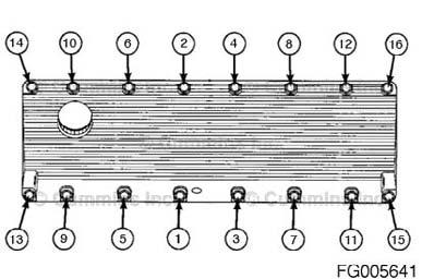
Figure 123
QSM11 Cummins Engine QSM11CUMMINSENG Page 79
MAINTENANCE PROCEDURES AT 2,000 HOURS OR 1 YEAR
Maintenance Procedures - Overview
General Information
All maintenance checks and inspections listed in previous maintenance intervals must also be performed now, in addition to those listed under this maintenance interval.
Air Cleaner Restriction
Maintenance Check
Mechanical Indicator NOTE: Do not remove the felt washer from the indicator. The felt washer absorbs moisture. A mechanical restriction indicator is available to indicate excessive air restriction through a dry-type air cleaner. This instrument can be mounted in the air cleaner outlet or on the instrument panel. The red flag (1) in the window gradually rises as the cartridge loads with dirt. After changing or replacing the cartridge, reset the indicator by pushing the reset button (2). Restriction or vacuum indicators need to be installed as close as possible to the turbocharger air inlet to obtain a true indication of restrictions.
Vacuum Indicator Vacuum switches actuate a warning light on the instrument panel when the air restriction becomes excessive.
CAUTION!
Never operate the engine without an air cleaner.Intake air must be filtered to prevent dirt and debris from entering the engine and causing premature wear. Figure 124


Figure 125
QSM11 Cummins Engine Page 80 QSM11CUMMINSENG
Maintenance Check
CAUTION!
The engine's intake air must be filtered to prevent dirt and debris from entering the engine. If any of the intake air piping is damaged or loose, unfiltered air will enter the engine, which can cause premature wear and engine failure.
Inspect the intake air piping once a week for cracked hoses, damage, or loose clamps. Replace damaged pipes and tighten loose clamps as necessary to make sure the air intake system does not leak. Torque Value: 8 Nm [71inlb] Check for corrosion of the intake system piping under the clamps and hoses. Corrosion can allow corrosive products and dirt to enter the intake system. Disassemble and clean the intake air piping as required.
Noise can be caused by an air leak from the: • Turbocharger-to-discharge-elbow connection Inspect for damage. Tighten loose clamps. Torque Value: 8 Nm [71inlb]
Figure 126


Figure 127

Figure 128
QSM11 Cummins Engine QSM11CUMMINSENG Page 81
• Turbocharger-to-exhaust-manifold mounting gasket Replace the gasket. Refer to Procedure 010-033 (Turbocharger) in Section A for turbocharger removal and installation.
• Turbine housing sealing surface exhaust leak. Tighten the turbine housing cap screws or V-band clamps. Torque Value: Cap Screws 14 Nm [120inlb] V-band 9 Nm [80inlb]
• Compressor housing sealing surface air leak. Tighten the compressor housing V-band clamp nut. Torque Value: Cap Screws 7 Nm [62inlb] V-band 9 Nm [80inlb]
Figure 129


Figure 130
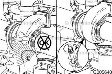
Figure 131
QSM11 Cummins Engine Page 82 QSM11CUMMINSENG
Inspect
Use an inductive charging and cranking system analyzer to loadtest the state of charge of maintenance-free batteries. If the state of charge is low, use a battery charger to charge the battery. Refer to the manufacturer's instructions. Replace the battery if it will not charge to the manufacturer's specifications or the battery will not maintain a charge.
If conventional batteries are used, remove the cell caps or covers and check the electrolyte (water and sulfuric acid solution) level.
WARNING!
Batteries can emit explosive gas. To reduce the possibility of personal injury, always ventilate the compartment before servicing the batteries. To reduce the possibility of arcing, remove the battery (-) negative cable first and attach the battery negative cable last.
NOTE: Maintenance-free batteries are sealed and do not require the addition of water. Fill each battery cell with water. Refer to the manufacturer's specifications. Refer to the accompanying table to determine the battery state of charge based on the specific-gravity readings.
Battery State of Charge Specific Gravity@ 27°C (80°F)
100% 1.260 - 1.280 75% 1.230 - 1.250 50% 1.200 - 1.220 25% 1.170 - 1.190
Discharged 1.110 - 1.130
Figure 132
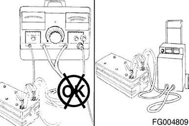

Figure 133
QSM11 Cummins Engine QSM11CUMMINSENG Page 83
Use a hydrometer to measure the specific gravity of each cell. NOTE: If the specific gravity of any cell is below 1.200, the battery must be charged. NOTE: Do not attempt to check the specific gravity of a battery immediately after adding water. If it is necessary to add water to allow use of the hydrometer, charge the battery several minutes at a high rate to mix the electrolyte.
Engine Mounts
Inspect
Check the torque on the engine-mounting nuts and bolts. Tighten any that are loose. Refer to the OEM service manual or manufacturer for torque specifications. Inspect the rubber for deterioration and age hardening. Replace any broken or lost bolts, cap screws, or damaged rubber.
Figure 134


Figure 135
Engine Steam Cleaning
Clean
WARNING!
Batteries can emit explosive gas. To reduce the possibility of personal injury, always ventilate the compartment before servicing the batteries. To reduce the possibility of arcing, remove the battery (-) negative cable first and attach the battery negative cable last.
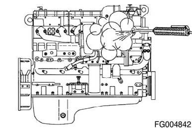
Steam is the best method of cleaning a dirty engine or a piece of equipment. If steam is not available, use a solvent to wash the engine. Protect all electrical components, openings, and wiring from the full force of the cleaner spray nozzle.
Figure 136
QSM11 Cummins Engine Page 84 QSM11CUMMINSENG
Install the sea water discharge line to the gear cooler.
Turbocharger
Maintenance Check
Tighten the turbocharger mounting nuts. Torque Value: 61 Nm [45ftlb]
Figure 137


Figure 138

Figure 139
QSM11 Cummins Engine QSM11CUMMINSENG Page 85
Check the turbine housing's sealing surface for exhaustleaks.If a leak is found, tighten the V-band clamp nut. Torque Value: 9 Nm [80inlb]
Check the compressor housing sealing surface for leaks.If a leak is found, tighten the V-band clamp nut. Torque Value: 9 Nm [80inlb]
Figure 140

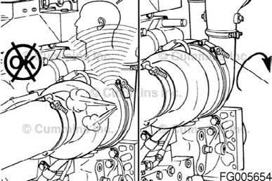
Figure 141
Water Pump
Maintenance Check
A streak or chemical buildup at the weep hole is not justification for water pump replacement. If a steady flow or drip of coolant or oil is observed at the weep hole, replace the water pump with a new or rebuilt unit. Refer to Procedure 008-062 (Water Pump) in Section A.

Figure 142
QSM11 Cummins Engine Page 86 QSM11CUMMINSENG
A small screwdriver or a similar tool can be used to remove any debris. Make sure the weep hole is open

Figure 143
Vibration Damper, Viscous
Inspect
CAUTION!
The silicone fluid in the vibration damper will become solid after extended service and will make the damper inoperative. An inoperative vibration damper can cause major engine or drivetrain failures.
Check the vibration damper for evidence of fluid loss, dents, and wobble. Inspect the vibration damper thickness for any deformation or raising of the damper cover plate. If any of these conditions are identified, contact your local Cummins Authorized Repair Location to replace the vibration damper. Viscous dampers have a limited life. The maximum damper life specifications are located in Maintenance Specifications (Section V). For vibration damper location, refer to Engine Diagrams in Engine Identification (Section E).
Figure 144

QSM11 Cummins Engine QSM11CUMMINSENG Page 87
Inspect
Inspect the idler pulley for: • Freedom of rotation • Cracked, chipped, or broken pulley grooves.
Turbocharger
Maintenance Check
Tighten the turbocharger mounting nuts. Torque Value: 61 Nm [45ftlb]
Check the turbine housing's sealing surface for exhaust leaks. If a leak is found, tighten the V-band clamp nut. Torque Value: 9 Nm [80inlb]
Check the compressor housing sealing surface for leaks. If a leak is found, tighten the V-band clamp nut. Torque Value: 9 Nm [80inlb]
QSM11 Cummins Engine Page 88 Figure 145

Figure 146
Figure 147
Figure 148
QSM11CUMMINSENG
General Information
Restore™, is a heavy-duty cooling system cleaner that removes corrosion, silica gel, and other deposits. The performance of Restore™, is dependent on time, temperature, and concentration levels. An extremely scaled or flow-restricted system, for example, can require higher concentrations of cleaners, higher temperatures, or longer cleaning times, or the use of Restore Plus™‚. Up to twice the recommended concentration levels of Restore™, can be used safely. Restore Plus™, must be used only at its recommended concentration level. Extremely scaled or fouled systems can require more than one cleaning.
Clean
WARNING!
Do not remove the pressure cap from a hot engine. Wait until the coolant temperature is below 50°C (120°F) before removing the pressure cap. Heated coolant spray or steam can cause personal injury.
Remove the radiator cap.
Drain the cooling system. Do not allow the cooling system to dry out. Do not remove the coolant filter.
WARNING!
Coolant is toxic. Keep away from children and pets. If not reused, dispose of in accordance with local environmental regulations. Figure 149

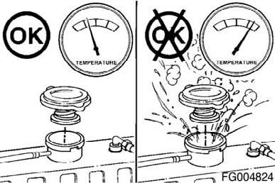
Figure 150
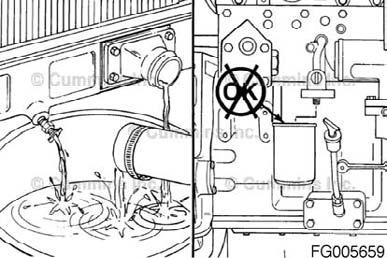
Figure 151
QSM11 Cummins Engine QSM11CUMMINSENG Page 89
Fleetguard® Restore™‚ contains no antifreeze. Do not allow the cooling system to freeze during the cleaning operation.
Immediately add 3.8 liters [1 gal] of Fleetguard® Restore™, Restore™, Plus, or the equivalent, for each 38 - 57 liters [10 - 15 gal] of cooling system capacity, and fill the system with plain water. Turn the cabin heater temperature switch to high to allow maximum coolant flow through the heater core. The blower does not have to be on.
Operate the engine at normal operating temperatures, at least 85°C (185°F), for 1 - 1-½ hours. Shut off the engine and drain the cooling system.
Fill the cooling system with clean water.
Operate the engine at high idle for five minutes with the coolant temperature above 85°C (185°F). Shut off the engine and drain the cooling system.
WARNING!
Do not remove the pressure cap from a hot engine. Wait until the coolant temperature is below 50°C (120°F) before removing the pressure cap. Heated coolant spray or steam can cause personal injury.
WARNING!
Coolant is toxic. Keep away from children and pets. If not reused, dispose of in accordance with local environmental regulations.
QSM11 Cummins Engine Page 90 Figure 152


Figure 153

Figure 154
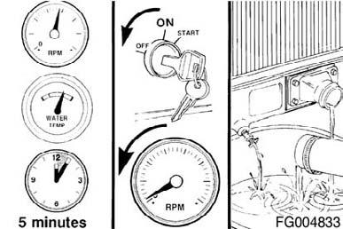
Figure 155
QSM11CUMMINSENG
Fill the cooling system with fully formulated coolant or a 50/50 mixture of fully formulated antifreeze and distilled water. Use a service filter to bring the coolant to the correct SCA concentration level. Refer to Procedure 018-024 (Cummins/ Fleetguard® Filter Specifications) in Section V for the correct filter to use. Install the pressure cap. Operate the engine until it reaches a temperature of 80°C (180°F) and check for coolant leaks.
CAUTION!
Do not add coolant to a hot engine. Engine castings can be damaged. Allow the engine to cool below 50°C (120°F) before adding coolant.
Flush
CAUTION!
Do not use caustic cleaners in the cooling system. Aluminum components will be damaged.
The cooling system must be clean to work correctly and to eliminate buildup of harmful chemicals.
Restore™, is a heavy-duty cooling system cleaner that removes corrosion, silica gel, and other deposits. The performance of Restore™, is dependent on time, temperature, and concentration levels. An extremely scaled or flow-restricted system, for example, can require higher concentrations of cleaners, higher temperatures, or longer cleaning times, or the use of Restore Plus™‚. Up to twice the recommended concentration levels of Restore™, can be used safely. Restore Plus™, must be used only at its recommended concentration level. Extremely scaled or fouled systems can require more than one cleaning.
Figure 156

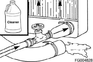
Figure 157
Figure 158
QSM11 Cummins Engine QSM11CUMMINSENG Page 91
Fleetguard® Restore™‚contains no antifreeze. Do not allow the cooling system to freeze during the cleaning operation.
After draining the coolant, immediately add 3.8 liters [1 gal] of Fleetguard™ Restore™, Restore Plus™, or equivalent, for each 38 - 57 liters [10 - 15 gal] of cooling system capacity, and fill the system with clean water. Turn the heater temperature switch to high to allow maximum coolant flow through the heater core. The blower does not have to be ON. Operate the engine at normal operating temperatures, at least 85°C (185°F), for one to one and a half hours. Shut off the engine and drain the cooling system.
Fill the cooling system with clean water.
WARNING!
Do not remove the pressure cap from a hot engine. Wait until the coolant temperature is below 50°C (120°F) before removing the pressure cap. Heated coolant spray or steam can cause personal injury. Figure 159
Figure 160
Figure 161
Figure 162
QSM11 Cummins Engine Page 92 QSM11CUMMINSENG
Coolant is toxic. Keep away from children and pets. If not reused, dispose of in accordance with local environmental regulations.
Operate the engine at high idle for five minutes with the coolant temperature above 85°C (185°F). Shut off the engine and drain the cooling system. If the water being drained is still dirty, the system must be flushed again until the water is clean.
Fill the cooling system with fully formulated coolant or a 50/50 mixture of fully formulated antifreeze and good distilled water. Use a service filter to bring the coolant to the correct SCA concentration level. Refer to Procedure 018-004 (Coolant Recommendations and Specifications) in Section V. Install the pressure cap. Operate the engine until it reaches a temperature of 80°C (180°F), and check for coolant leaks.
Fill
Close the radiator drain valves. Install the lower radiator hose(s). Tighten the hose clamps. Torque Value: 5 Nm [40inlb]
WARNING!
Coolant is toxic. Keep away from children and pets. If not reused, dispose of in accordance with local environmental regulations.
CAUTION!
To reduce the possibility of engine damage, do not add coolant while the engine is hot. Figure 163

Figure 164
QSM11 Cummins Engine QSM11CUMMINSENG Page 93
Cummins recommends using either a 50/50 mixture of distilled water and fully-formulated antifreeze, or fully-formulated coolant when filling the cooling system. The fully-formulated antifreeze or coolant must meet TMC RP329 or TMC RP330 specifications. Distilled water is important for cooling system performance. Excessive levels of calcium and magnesium contribute to scaling problems, and excessive levels of chlorides and sulfates cause cooling system corrosion.
Cummins recommends using Fleetguard® COMPLEAT ES. It is available in glycol forms (ethylene and propylene) and complies with TMC RP329 and RP330 standards.
Fill the cooling system with heavy-duty coolant and install the correct service filter. Refer to Procedure 018-004 (Coolant Recommendations and Specifications) in Section V.
Calcium Magnesium (Hardness) Maximum 170 ppm as (CaCO3 + MgCO3)
Chloride 40 ppm as (CI) Sulfate 100 ppm as (SO4)
Water Quality

Figure 165

Figure 166

Figure 167
QSM11 Cummins Engine Page 94 QSM11CUMMINSENG
Fill the cooling system with coolant to the bottom of the fill neck in the radiator fill (or expansion) tank. NOTE: Some radiators have two fill locations, both of which must be filled when the cooling system is drained.
Install the radiator or expansion tank fill cap. Operate the engine until it reaches a temperature of 82°C (180°F), and check for leaks.
Shut off the engine and allow to cool.
WARNING!
Do not remove the pressure cap from a hot engine. Wait until the coolant temperature is below 50°C (120°F) before removing the pressure cap. Heated coolant spray or steam can cause personal injury. Figure 168

Figure 169

Figure 170


