
9 minute read
Maintenance Procedures at 500 Hours or 6 Months


Maintenance Procedures - Overview
General Information
All maintenance checks and inspections listed in previous maintenance intervals must also be performed now, in addition to those listed under this maintenance interval.
Fuel Filter (Spin-on Type)
Remove
Clean the area around the fuel filter and fuel filter head. Remove the fuel filter with filter wrench.
Remove the thread adapter sealing ring (1). Use a clean, lint-free towel to clean the gasket surface on the fuel filter head.
Figure 76

Figure 77
QSM11 Cummins Engine QSM11CUMMINSENG Page 63
Install
Use the correct filter(s) for your engine. Refer to Procedure 018024 (Cummins/Fleetguard® Filter Specifications) for the fuel filter specifications. Clean the area around the fuel filter and fuel filter head. Lubricate the fuel filter gasket with clean engine oil. Fill the new fuel filter with clean diesel fuel.
Install the new thread adapter sealing ring (1) supplied with the new filter.
Install the filter on the filter head. Turn the filter until the gasket contacts the filter head surface.
CAUTION!
If the filter canister is damaged in any way, do not use it. Dents or scrapes can lead to a rupture or premature failure of the filter.
CAUTION!
Mechanical overtightening of the filter can distort the threads and damage the fuel filter seal. Figure 78
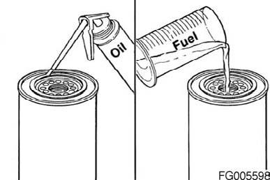

Figure 79

Figure 80
QSM11 Cummins Engine Page 64 QSM11CUMMINSENG
Tighten the filter, by hand, an additional ½ to ¾ of a turn after the gasket contacts the filter head surface, or as specified by the filter manufacturer.
Lubricating Oil and Filters
Drain
WARNING!
To reduce the possibility of personal injury, avoid direct contact of hot oil with your skin.
WARNING!
Some state and federal agencies have determined that used engine oil can be carcinogenic and cause reproductive toxicity. Avoid inhalation of vapors, ingestion, and prolonged contact with used engine oil. If not reused, dispose of in accordance with local environmental regulations.
Change the lubricating oil and filter at the specified oil change interval. Refer to the Procedure 102-002 (Maintenance Schedule) in Section 2 to find the correct change interval for your application. Operate the engine until the water temperature reaches 60°C (140°F). Shut off the engine. Remove the oil drain plug from the bottom of the lubricating oil pan. Do not remove the plugs on either side of the oil pan to drain the oil. They will not allow the oil to drain completely. Fittings used in the bottom drain opening of the oil pan other than Cummins-specified parts must not exceed the size or weight limits. Refer to Procedure 018-017 (Lubricating Oil System Specifications) in Section V.
Figure 81


Figure 82
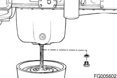
Figure 83
QSM11 Cummins Engine QSM11CUMMINSENG Page 65
Use a high-quality multiviscosity oil such as Valvoline® Premium Blue™ Valvoline® Premium Blue™ 2000, or equivalent. Choose the correct oil for your operating climate as outlined in Procedure 018-003 (Cummins Recommendations and Specifications) in Section V.
Fill the engine with clean oil to the H (high) mark on the dipstick. For total system capacity including filter, refer to Procedure 018017 (Lubricating Oil System Specifications) in Section V. NOTE: Check the Centinel™‚makeup tank oil level, if equipped.
CAUTION!
Engine oil pressure must be indicated on the gauge within 15 seconds after starting. If oil pressure is not registered within 15 seconds, shut off the engine immediately to avoid engine damage. Confirm the correct oil level is in the oil pan.
Operate the engine at idle speed to inspect for leaks at the filter and the drain plug.
Shut off the engine. Wait approximately 10 minutes for the oil to drain back from the upper portion of the engine to the oil pan. Check the oil level again. Add oil as necessary to bring the level up to the H (high) mark on the dipstick.
Figure 84


Figure 85

Figure 86
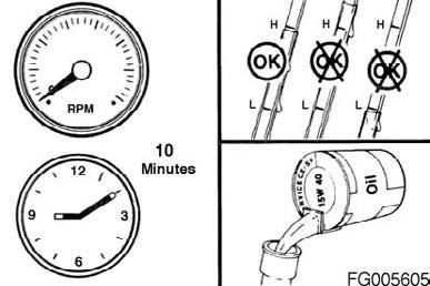
Figure 87
QSM11 Cummins Engine Page 66 QSM11CUMMINSENG
Remove
Clean the area around the lubricating oil filter head. Use oil filter wrench, Part Number 3375049, or equivalent, to remove the filter. Clean the gasket surface of the filter head. The O-ring can stick on the filter head. Make sure it is removed.
Install
CAUTION!
Do not replace LF9001 lubricating filter with extended length LF9000 lubricating filter without verifying adequate clearance with suspension and/or chassis at extremes of travel. The engine can be damaged.
Use the correct oil filter for your engine. Cummins Inc. requires a lubricating oil filter(s) be used that meets the specifications given in Procedure 018-024 (Cummins/ Fleetguard Filter Specifications) in Section V. Combination lubricating filter • Cummins Part Number 3406810 or Fleetguard® Part Number LF9000.
• Cummins Part Number 3406809 or Fleetguard® Part Number LF9001.
CAUTION!
Fill the lubricating oil filter with clean lubricating oil. The lack of lubrication during the delay until the filter is pumped full of oil at start-up is harmful to the engine.
CAUTION!
Mechanical overtightening of the filter can distort the threads or damage the filter seal. Figure 88


Figure 89
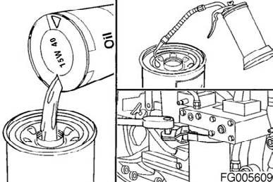
Figure 90
QSM11 Cummins Engine QSM11CUMMINSENG Page 67
Fill the filter with clean oil. Choose the correct oil for your operating climate as outlined in Procedure 018-003 (Cummins Recommendations and Specifications) in Section V. The LF9001 filter capacity is 2.6 liters [0.7 gal]. The LF9000 filter capacity is 3.0 liters [0.8 gal]. Apply a light film of oil to the gasket sealing surface before installing the new filter. Install the filter on the filter head. Tighten the filter until the gasket contacts the filter head surface. Use oil filter wrench, Part Number 3375049, or equivalent, to tighten the filter to the specifications supplied with the filter.
Operate the engine at idle speed for three minutes to inspect for leaks at the filter(s).
CAUTION!
Engine oil pressure must be indicated on the gauge within 15 seconds after starting. If oil pressure is not registered within 15 seconds, shut off the engine immediately to avoid engine damage. Confirm the correct oil level in the oil pan.

Figure 91
Coolant Filter
General Information
Change the coolant filter at every oil and filter change interval unless the supplemental coolant additive (SCA) level is over 3 units. See Supplemental Coolant Additive-Maintenance check in this section. The SCA level must be tested every six months. The correct coolant filter to be used is determined by the total cooling system capacity and other operational factors. For the correct filter selection, Refer to Coolant Recommendations and Specifications in Maintenance, Procedure 018-004, in Section V.

Figure 92
QSM11 Cummins Engine Page 68 QSM11CUMMINSENG
WARNING!
Do not remove the pressure cap from a hot engine. Wait until the coolant temperature is below 50°C (120F) before removing the pressure cap. Heated coolant spray or steam can cause personal injury.
Remove the cooling system pressure cap.
Turn the valve on the remote-mounted coolant filter head to the "OFF" position.
Turn the valve on the coolant filter head to the "OFF" position.
Remove and discard the coolant filter. Using a lint free cloth, clean the coolant filter head gasket's surface.
WARNING!
A small amount of coolant can leak when servicing the coolant filter with the shutoff valve in the "OFF" position. To reduce the possibility of personal injury, avoid contact with hot coolant. Figure 93


Figure 94

Figure 95
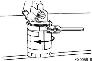
Figure 96
QSM11 Cummins Engine QSM11CUMMINSENG Page 69
CAUTION!
If the filter canister is damaged in any way, do not use it. Dents or scrapes can lead to a rupture or premature failure of the filter.
Apply a thin film of clean engine oil to the gasket sealing surface before installing the new coolant filter.
Install the new filter on the filter head. Tighten the filter until the gasket contacts the filter head surface.
Tighten the filter an additional ½ to ¾ of a turn, or as specified by the filter manufacturer.
Turn the valve on the filter head to the "ON" position, and install the coolant system pressure cap.
CAUTION!
Mechanical overtightening can distort the filter threads or damage the filter head.
CAUTION!
The valve(s) must be in the "ON" position to reduce the possibility of engine damage. Figure 97


Figure 98

Figure 99

Figure 100
QSM11 Cummins Engine Page 70 QSM11CUMMINSENG
Operate the engine and check for leaks. After the air has been purged from the system, check the coolant level again.
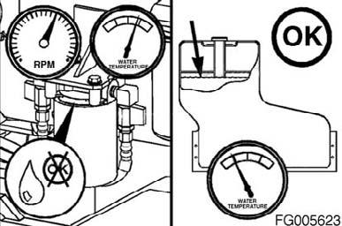
Figure 101
Maintenance Check
Supplemental Coolant Additive (SCA) Check the SCA concentration level: • At least twice a year • At every subsequent oil drain interval if the concentration is above 3 units • Whenever coolant is added to the cooling system between filter changes. Use Fleetguard® coolant test kit, Part No. CC2602, to check the SCA concentration level. Instructions are included with the test kit. Refer to Coolant Recommendations and Specifications in Maintenance Specifications (Section V) for the correct SCA and antifreeze level. Antifreeze
Check the antifreeze concentration. Use a mixture of 50- percent water and 50% ethylene glycol or propylene glycol-based antifreeze to protect the engine to -32°C (-26°F) year-around. The Fleetguard® refractometer, Part Number C2800, provides a reliable, easy-to-read, and accurate measurement of freezing point protection and glycol (antifreeze) concentration. Antifreeze is essential in every climate.
CAUTION!
Over concentration of antifreeze or use of high-silicate antifreeze can damage the engine. Figure 102


Figure 103
QSM11 Cummins Engine QSM11CUMMINSENG Page 71
Antifreeze broadens the operating temperature range by lowering the coolant freezing point and by raising its boiling point. The corrosion inhibitors also protect the cooling system components from corrosion and prolong component life.
Engine Wiring Harness
Maintenance Check
Marine and Industrial Applications
WARNING!
Never touch any wiring connection when the starter switch is in the "ON" position. An electrical shock or personal injury can result.
Inspect all wiring connections and wiring harnesses for damage. Faulty wiring can cause improper engine operation and poor performance.
Figure 104


