
7 minute read
Maintenance Procedures at Daily Interval


Daily Maintenance Procedures - Overview
General Information
Preventative maintenance begins with day-to-day awareness of the engine and its system. Before starting the engine, check the oil and coolant levels. Look for: • Leaks • Loose or damaged parts • Worn or damaged belts • Any change in engine appearance. • Odor of fuel
Engine Operation Report
The engine must be maintained in top mechanical condition if the operator is to get optimum satisfaction from its use. The maintenance department needs daily running reports from the operator to make necessary adjustments in the time allocated. The daily running report also helps to make provisions for more extensive maintenance work as the reports indicate the necessity. Comparison and intelligent interpretation of the daily report, along with a practical follow-up action, will eliminate most failures and emergency repairs. Report to the maintenance department any of the following conditions: • Low lubricating oil pressure • Low power • Power increases or engine surge • Erratic or no accelerator control or response • Any warning lights flashing or staying on • Abnormal water or oil temperature • Unusual engine noise • Excessive smoke • Excessive use of coolant, fuel, or lubricating oil • Any fuel, coolant, or lubricating oil leaks • Loose or damaged parts • Worn or damaged belts
QSM11 Cummins Engine QSM11CUMMINSENG Page 55
Unusual Engine Noise
During daily maintenance checks, listen for any unusual engine noise that can indicate that service is required.
Fuel-Water Separator
Drain
WARNING!
Drain the water-fuel separator into a container and dispose of in accordance with local environmental regulations.
Cummins Inc. requires a fuel-water separator or fuel filter be installed in the fuel supply system. Drain the water and sediment from the separator daily.
Spin-on Type Shut off the engine. Use your hand to open the drain valve. Turn the valve counterclockwise approximately 3 1/2 turns until the valve drops down 25.4 mm [1 in] and draining occurs. Drain the filter sump until clear fuel is visible.
To close the valve, lift the valve and turn clockwise until it is hand-tight.
CAUTION!
When closing the drain valve, do not overtighten the valve. Overtightening can damage the threads. Figure 57
Priming pump
Primary fuel filter & cartridge
Figure 58
Drain plug
FG0004942

Figure 59
QSM11 Cummins Engine Page 56 QSM11CUMMINSENG
Maintenance Check
CAUTION!
Never operate the engine with oil level below the L (low) mark or above the H (high) mark. Poor engine performance or engine damage can occur.
The engine must be level when checking the oil level to make sure the measurement is correct. Shut off the engine for an accurate reading. Wait at least 15 minutes after shutting off the engine to check the oil level. This allows time for the oil to drain into the oil pan. For additional lubricating oil recommendations and oil pan capacity information, refer to Maintenance Specifications (Section V).
Coolant Level
Maintenance Check
WARNING!
Do not remove a pressure cap from a hot engine. Wait until the coolant temperature is below 50°C (120°F) before removing the pressure cap. Heated coolant spray or steam can cause personal injury.
CAUTION!
Never use a sealing additive to stop leaks in the cooling system. This can result in cooling system plugging and inadequate coolant flow, causing the engine to overheat.
The coolant level must be checked daily.
Figure 60

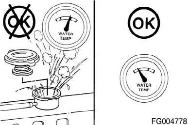
Figure 61
QSM11 Cummins Engine QSM11CUMMINSENG Page 57
Do not add cold coolant to a hot engine. Engine castings can be damaged. Allow the engine to cool to below 50°C (120°F) before adding coolant.
Make up coolant added to the engine must be mixed with the correct proportions of antifreeze, supplemental coolant additive, and water to avoid engine damage. Coolant recommendations and specification details on correct mixing of coolant can be found in “Maintenance Specifications” on page223. Fill the cooling system with coolant to the bottom of the fill neck in the radiator fill or expansion tank. NOTE: Some radiators have two fill necks, both of which must be filled when the cooling system is drained.

Figure 62

Figure 63
Cooling System Hoses
Maintenance Check
Inspect the cooling system hoses and hose connections for leaks or deterioration. Particles of deteriorated hose can be carried through the cooling system and restrict or clog small passages, especially the heat exchanger and lubricating oil cooler, and partially stop circulation. Replace as necessary.

Figure 64
QSM11 Cummins Engine Page 58 QSM11CUMMINSENG
Inspect for Reuse
A visual inspection of the cooling fan is required daily. Check for cracks, loose rivets, and bent or loose blades. Check the fan to make sure it is securely mounted. Tighten the cap screws, if necessary.
Replace original equipment fan that is damaged with a fan of the identical part number. Cummins Inc. must approve any other fan changes to be covered under warranty. Refer to the vehicle or equipment manufacturer's specifications for cap screw torque.
WARNING!
Do not straighten a bent fan blade or continue to use a damaged fan. A bent or damaged fan blade can fail during operation and cause personal injury or property damage. Figure 65


Figure 66

Figure 67
QSM11 Cummins Engine QSM11CUMMINSENG Page 59
Maintenance Check
Poly-Vee Belt Inspect the belts daily. Check the belt for intersecting cracks. Traverse (across the belt width) cracks are acceptable. Longitudinal (direction of belt length) cracks that intersect with transverse cracks are not acceptable. Replace the belt if it is frayed or has pieces of material missing. Refer to Section A for belt adjustment and replacement procedures. Belt damage can be caused by: • Incorrect tension • Incorrect size or length • Pulley misalignment • Incorrect installation • Severe operating environment • Oil or grease on the side of belts. Cogged Belt Inspect the belts daily. Replace the belts if they are cracked, frayed, or have chunks of material missing. Small cracks are acceptable. Adjust the belts that have a glazed or shiny surface, which indicates belt slippage. Correctly installed and tensioned belts will show even pulley and belt wear. Refer to Section A for belt adjustment and replacement procedures. Belt damage can be caused by: • Incorrect tension • Incorrect size or length • Pulley misalignment • Incorrect installation • Severe operating environment • Oil or grease on the belts
Figure 68


Figure 69
QSM11 Cummins Engine Page 60 QSM11CUMMINSENG
Measure the belt tension in the center span of the pulleys. Refer to the Belt Tension Chart in Section V for the correct gauge and tension value for the belt width used. An alternate method (deflection method) can be used to check belt tension by applying 110 N [25 lbf] force between the pulleys on v-belts. If the deflection is more than one belt thickness per foot of pulley center distance, the belt tension must be adjusted. Refer to Section A for adjustment procedures.
For cogged belts, make sure that the belt tension gauge is positioned so the center tensioning leg is placed directly over the high point (hump) of a cog. Other positioning will result in incorrect measurement.
Figure 70


Figure 71
Crankcase Breather Tube
Maintenance Check
Inspect the breather tube for sludge, debris, or ice in the tube. Inspect the tube more frequently in icy conditions.

Figure 72
Charge-Air Piping
Maintenance Check
Inspect the charge-air piping and hoses for leaks, holes, cracks, or loose connections. Tighten the hose clamps if necessary. Refer to the vehicle or equipment manufacturer's specifications for the correct torque value.
QSM11 Cummins Engine Figure 73

QSM11CUMMINSENG Page 61
Maintenance Check
Mechanical Indicator NOTE: Do not remove the felt washer from the indicator. The felt washer absorbs moisture. A mechanical restriction indicator is available to indicate excessive air restriction through a dry-type air cleaner. This instrument can be mounted in the air cleaner outlet or on the instrument panel. The red flag (1) in the window gradually rises as the cartridge loads with dirt. After changing or replacing the cartridge, reset the indicator by pushing the reset button (2). Restriction or vacuum indicators need to be installed as close as possible to the turbocharger air inlet to obtain a true indication of restrictions.
Vacuum Indicator Vacuum switches actuate a warning light on the instrument panel when the air restriction becomes excessive.
CAUTION!
Never operate the engine without an air cleaner. Intake air must be filtered to prevent dirt and debris from entering the engine and causing premature wear. Figure 74


