
20 minute read
Operating Instructions


Operating Instructions - Overview
Correct care of your engine will result in longer life, better performance, and more economical operation. Follow the daily maintenance checks listed in Maintenance Guidelines (Section 2). The new Cummins engine associated with this manual does not require a "break-in" procedure. This section of the manual provides all the necessary information required for proper engine operation. Check the oil pressure indicators, temperature indicators, warning lights, and other gauges daily to make sure they are operational.
WARNING!
DO NOT OPERATE A DIESEL ENGINE WHERE THERE ARE OR CAN BE COMBUSTIBLE VAPORS. The vapors can be sucked through the air intake system and cause engine acceleration and overspeeding that can result in a fire, an explosion, and extensive property damage. Numerous safety devices are available, such as air intake shutoff devices, to minimize the risk of overspeeding where an engine, due to its application, due to a fuel spill or gas leak. Remember, Cummins has no way of knowing the use you have for your engine. THE EQUIPMENT OWNER AND OPERATOR ARE RESPONSIBLE FOR SAFE OPERATION IN A HOSTILE ENVIRONMENT. CONSULT YOUR CUMMINS AUTHORIZED REPAIR LOCATION FOR FURTHER INFORMATION. Figure 11

Figure 12
QSM11 Cummins Engine Page 32 QSM11CUMMINSENG
Cummins recommends the installation of an air intake shutoff device or a similar safety device to minimize the risk of overspeeding where an engine, due to the vehicle, vessel or equipment being operated in a combustible environment, such as due to a fuel spill or gas leak.
CAUTION!
Do not expose the engine to corrosive chemicals. Corrosive chemicals can damage the engine.

Figure 13
Normal Starting Procedure
CAUTION!
The engine must have adequate oil pressure within 15 seconds after starting. If the WARNING light indicating low oil pressure has not gone out or there is no oil pressure indicated on a gauge within 15 seconds, shut off the engine immediately to avoid engine damage. The low oil pressure troubleshooting procedure is located in Troubleshooting Symptoms (Section TS).
Idle the engine 3 - 5 minutes before operating with a load.
Figure 14


Figure 15
QSM11 Cummins Engine QSM11CUMMINSENG Page 33
Increase the engine speed (rpm) slowly to provide adequate lubrication to the bearings and to allow the oil pressure to stabilize.
Do not keep the engine at low idle for long periods. Idling for periods longer than 10 minutes can damage an engine, causing combustion chamber temperatures to drop so low the fuel will not burn completely. This will cause carbon to build up around the injector spray holes and piston rings, and can cause the valves to stick.
If the engine coolant temperature becomes too low, below 60°C (140°F), raw fuel will wash the lubrication oil off the cylinder walls and dilute the crankcase oil. Fuel dilution adversely affects lubricating oil properties and can shorten engine life. Utilize the fast idle to prevent these conditions.
Figure 16


Figure 17

Figure 18
WARNING!
Batteries can emit explosive gases. To avoid personal injury, always ventilate the compartment before servicing the batteries. To avoid arcing, remove the negative (-) battery cable first and attach the negative (-) battery cable last.

Figure 19
QSM11 Cummins Engine Page 34 QSM11CUMMINSENG
When using jumper cables to start the engine, make sure to connect the cables in parallel: Positive (+) to positive (+) and negative (-) to negative (-). When using an external electrical source to start the engine, turn the disconnect switch to the "OFF" position. Remove the key before attaching the jumper cables.
The accompanying illustration shows a typical parallel battery connection. This arrangement doubles the cranking amperage. This illustration shows a typical series battery connection. This arrangement, positive (+) to negative (-), doubles the voltage.
Cold Weather Starting
General Information
Follow the Normal Starting Procedures in this section. In cold weather, the engine can run at idle only longer.
Using Starting Aids
WARNING!
Do not use starting fluids with this engine. This engine is equipped with an intake air heater; use of starting fluid can cause an explosion, fire, personal injury, severe damage to the engine and property damage.
Cold weather starting aids are available for your engine. Contact the local Cummins Authorized Repair Location for more information.
Figure 20

Figure 21
QSM11 Cummins Engine QSM11CUMMINSENG Page 35
Follow the Normal Starting Procedure in this section. The engine will run at idle only until the minimum oil pressure is detected by the ECM.
Operating the Engine
Normal
If equipped, monitor the oil pressure and coolant temperature gauges frequently. Refer to Lubricating Oil System specifications and Cooling System specifications, in Maintenance Specifications (Section V) for recommended operating pressures and temperatures. Shut off the engine if any pressure or temperature does not meet the specifications. Continuous operation with engine coolant temperature above or below the engine coolant temperature specifications listed in Maintenance Specifications (Section V) can damage the engine. If an overheating condition starts to occur, reduce the power output of the engine by releasing the accelerator pedal or lever or shifting the transmission to a lower gear, or both, until the temperature returns to the normal operating range. If the engine temperature does not return to normal, shut off the engine, and refer to Troubleshooting Symptoms (Section TS), or contact a Cummins Authorized Repair Location.
Most failures give an early warning. Look and listen for changes in performance, sound, or engine appearance that can indicate service or engine repair is needed.
Figure 22


Figure 23

Figure 24
QSM11 Cummins Engine Page 36 QSM11CUMMINSENG
Some changes to look for are: • Engine misfires • Vibration • Unusual engine noises • Sudden changes in engine operating temperatures or pressures • Excessive smoke • Loss of power • An increase in oil consumption • An increase in fuel consumption • Fuel, oil, or coolant leaks.
Cold Weather
It is possible to operate engines in extremely cold environments if they are properly prepared and maintained. Satisfactory performance of an engine in low ambient temperature conditions requires modification of the engine, surrounding equipment, operating practices and maintenance procedures. The correct engine coolant lubricating oil and fuels must be used for the cold weather range in which the engine is being operated. Below are the recommendations for these critical engine fluids:
Ambient Temperature
0° - -32°C (32° - -25°F) Use 50% ethylene glycol antifreeze and 50% water for the engine coolant mixture. Refer to Maintenance Specifications (Section V) Lubricating Oil recommendations for the correct specifications. The Diesel fuel must have maximum cloud and pour points 6°C (10°F) lower than the ambient temperature in which the engine operates.
-32° - -54°C (-25° - -65°F) Use 60% ethylene glycol antifreeze and 40% water for the engine coolant mixture. Refer to Maintenance Specifications (Section V) Lubricating Oil recommendations for the correct specifications. The Diesel fuel must have maximum cloud and pour points 6°C (10°F) lower than the ambient temperature in which the engine operates. The following cold weather operating aids are required for cold weather situations:
QSM11 Cummins Engine QSM11CUMMINSENG Page 37

Figure 25
Engine Operating Range
CAUTION!
Do not operate the engine at full throttle operation below peak torque rpm (refer to engine data plate for peak torque rpm) for more than 30 seconds. Operating the engine at full throttle below peak torque will shorten engine life to overhaul, can cause serious engine damage, and is considered engine abuse.
Cummins engines are designed to operate successfully at full throttle under transient conditions down to peak torque engine speed. This is consistent with recommended operating practices.
Figure 26

QSM11 Cummins Engine Page 38 QSM11CUMMINSENG
Do not operate the engine beyond the maximum engine speed. Operating the engine beyond the maximum engine speed can cause severe engine damage. Use proper operating techniques for the vehicle, vessel, or equipment to prevent engine overspeed. The maximum engine speed specification is listed in Maintenance Specifications (Section V).
Engine Shutdown
For engines with shielded exhaust manifold and turbochargers, allow the engine(s) to idle for 10 - 12 minutes before shutting off after full load operation. Otherwise, allow the engine(s) to idle 3 - 5 minutes before shutting off after full load operation. This allows the cool down of pistons, cylinders, bearings and turbocharger components. If the engine does not shut down, refer to Troubleshooting Symptom (Section TS). Turn the starter switch to the "OFF" position.
Electronic Controlled Fuel System
General Information
The system is an electronically controlled fuel injection system that optimizes fuel economy and reduces exhaust emissions. It does this by controlling the torque and horsepower curve, AFC function, engine high-speed, low idle, and road speed.

Figure 27
QSM11 Cummins Engine QSM11CUMMINSENG Page 39
Light Operation
Feature Operator Message Warning Engine Stop Engine Engine Maintenance
Light Display Power-up light test On then off On then off On then off Diagnostics Fault code flash out Flash once / code Flash code Number
Engine Protection System problem Slow flash Maintenance Monitor Interval expired 3x5 fast flash Maintenance Monitor Interval rest 3x5 fast flash Diagnostics Nonfatal system error On steady Diagnostics Fatal system error On steady Diagnostics Maintenance required On steady
If the STOP or Warning light comes on when the engine is running, it means a fault code has been recorded. The light will remain on as long as the fault exists. The severity of the fault will determine the light that will come on.
Stop Engine Light
The STOP ENGINE light is a red light. This light indicates that the engine needs to be shut down before permanent damage occurs to the engine. NOTE: The engine should be shut off as soon as it can be shut off safely. The engine should not be run until the fault is corrected. This light is also used to flash out the fault code number in the diagnostic mode.
Figure 28
STOP STOP
Warning Engine Light
The Warning ENGINE light comes on during a nonfatal system error. The engine can still be run, but the fault should be corrected as soon as possible. NOTE: In the diagnostic mode, the warning engine light will flash after the shut down engine light completes the three-digit fault code.
Figure 29
QSM11 Cummins Engine Page 40 QSM11CUMMINSENG
Engine Maintenance Light
The ENGINE MAINTENANCE light comes on when engine maintenance is required.
CHECK
Engine Diagnostics
When a fault or maintenance light is lit, the engine diagnostics switch allows the operator to view the fault codes. Active fault codes can be viewed using the shut down engine warning light as described below.
To view the fault codes: • The engine must be shut off (not running) • The starter switch must be in the "ON" position • The ENG DIAG switch (1) must be in the "ON" position.
If there are fault codes to be displayed, the Warning engine light will flash momentarily. Then the shut down engine light will flash the first, second, and third digits of the fault code. Example: • Fault Code 244 • 4 flashes, pause • 3 flashes, pause • 2 flashes. NOTE: The warning engine light will flash between each fault code. The pattern repeats itself until the fault is cleared or the switch is turned off.
Figure 30
FG000045
QSM11 Cummins Engine Figure 31
Diag
FG006223

Figure 32

Figure 33
QSM11CUMMINSENG Page 41
To view the next fault code, press the rpm ± switch (4) in the (+) direction. To view the previous fault code, press the rpm ± switch (4) in the (-) direction. NOTE: Engine lights are actually located in the console of front instrument panel. Engine diagnostics and rpm ± switches are actually located on top of right stand panel.
There are two types of fault codes: • Engine electronic fuel system codes • Engine protection system codes.
The engine electronic fuel system fault codes can be seen on the WARNING and STOPLIGHTS in the cabin panel. Inactive fault codes cannot be blinked out on the two lights in the cabin panel. An INSITETM service tool must be used to read inactive faults in the ECM. Refer to your Cummins Authorized Repair Location.
The STOP fault light will be red. The WARNING light will be yellow or red, depending on the OEM's preference. When the vehicle starter switch is turned on and the diagnostic switch is off, all three lights will illuminate to check their operation. The lights will go off in sequence after about 2 seconds. The lights will remain off until a fault code is recorded. If a light remains on, an active fault exists. If the STOPLIGHT (red) is illuminated while operating, the fault can be engine disabling. The equipment must be shut off as soon as it can be done in a safe manner. The equipment must remain parked as long as this fault exists. If the WARNING light (yellow or red) is illuminated, the equipment can be safely operated, but the fault must be corrected as soon as possible.
O
I
n/min+-
O II
Figure 34
FG005810

Figure 35

Figure 36

Figure 37
QSM11 Cummins Engine Page 42 QSM11CUMMINSENG
The engine protection system logs separate fault codes for outof-range conditions associated with any of the following sensors: • Coolant temperature • Coolant level • Oil temperature • Oil pressure • Intake manifold temperature
If the engine protection system illuminates while driving, it means a fault code has been recorded. The light will remain on as long as the fault exists, and engine power and speed will gradually be reduced. If the out-of-range conditions continue, the light will start to flash or blink. If the engine protection shutdown feature is enabled, the engine will be shut down to help prevent engine damage. The fault must be corrected as soon as possible.
Shut down engine. To check for engine electronic fuel system and engine protection system fault codes, move the diagnostic switch to the "ON" position, or connect the shorting plug into the diagnostic connector.
Figure 38
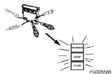

Figure 39
Figure 40
QSM11 Cummins Engine QSM11CUMMINSENG Page 43
The fuel system on a QSM11 engine consists of: 1. Fuel shutoff valve 2. Oil pressure sensor and temperature sensor 3. Intake manifold boost sensor 4. Cooling plate 5. ECM 6. Engine wiring harness Deutsch connector.
7. OEM wiring harness 8. Engine wiring harness Deutsch connector 9. Fuel out 10. Fuel in 11. Fuel gear pump 12. Engine position sensor (EPS) 13. Coolant temperature sensor (in thermostat support) 14. Coolant level sensor (in overflow tank) - optional 15. Intake manifold temperature sensor 16. Ambient air pressure sensor
The idle adjustment is in the cabin panel. Use this switch to adjust the engine idle speed in increments of 25 rpm. • Industrial - 700 - 1200 rpm Each time the switch is briefly moved to the minus (-) position, the idle speed is decreased by 25 rpm. When the switch is briefly moved to the plus (+) position, the idle speed is increased by 25 rpm.
Figure 41


Figure 42
Figure 43
n/min
FG005813
QSM11 Cummins Engine Page 44 QSM11CUMMINSENG
General Information
The system provides additional electronic features that enhance engine and vehicle performance and control. These are programmable features in the ECM. For more information on additional features, refer to the Troubleshooting and Repair Manual, Electronic Control System, ISM and QSM11 Engines, Bulletin 3666266; or contact a Cummins Authorized Repair Location.
Alternative Low Idle Speed
This feature allows for two different low idle speed settings with normal throttle control above the low idle speed setting for shortening the time of engine warming up and improving machine acceleration at engine low speed area. • 900 - 1200 rpm
The alternate low idle feature is activated whenever the normally closed alternate low idle switch is opened and 5 VDC are detected on the alternate low idle signal line. The following art illustrates an alternate low idle speed that is above the normal low idle speed.
Figure 44

HI
Figure 45
n/min
FG005814

Figure 46
QSM11 Cummins Engine QSM11CUMMINSENG Page 45
Switchable (Alternate) Torque
This feature enables an alternative electronically controlled maximum engine torque curve for optimum operating efficiency in loaded versus unloaded conditions. • Primary torque curve (for heavy duty working) • Alternate torque curve (for light duty working) (=Economy mode)
The alternate torque feature is activated whenever the normally closed alternate torque switch is opened and 5 VDC are detected on the alternate torque signal line. Five torque versus engine speed points define the alternate torque curve.
Duty Cycle Monitor
The duty cycle monitor tracks the time the engine spends in 50 different operating regions. These operating regions are based on engine speed and engine torque.
O
I
Figure 47
FG005811

Figure 48

Figure 49
QSM11 Cummins Engine Page 46 QSM11CUMMINSENG
This feature provides two short-term 500 hour resettable data blocks and one long-term 100,000 hour nonresettable data block.
Fuel Consumption Rate Logger
The fuel consumption rate feature allows an electronic service tool to access fuel consumption data (1=time, 2=gallons/hour).
This feature provides two resettable 40 hour fuel consumption periods (1 and 2). Each period records fuel consumption data in forty 1 hour segments. These 40 data segments can be graphed to show fuel consumption over both 40 hour periods (A=hours, B=gallons/hour).
Figure 50


Figure 51

Figure 52
QSM11 Cummins Engine QSM11CUMMINSENG Page 47
An instantaneous fuel consumption rate and a nonresettable lifetime or running average fuel consumption rate are available on the monitor screen of an electronic service tool. In addition, the two 40 hour fuel consumption periods are individually resettable using an electronic service tool.
Maintenance Monitor
NOTE: The maintenance monitor is designed to alert the operator of the need for a routine maintenance stop. Maintenance records must still be maintained for historical purposes. NOTE: The maintenance monitor uses data received from the ECM to determine the amount of fuel burned. Whenever a VSS, injector circuit, or battery voltage fault has occurred, the maintenance monitor data can be inaccurate. The maintenance monitor is an optional feature that will alert the operator when it is time to change oil and perform any other simultaneous maintenance tasks. The maintenance monitor continuously monitors the time the engine has been operating and the amount of fuel burned to determine when it is time to change oil. The operator must still be alert for any other indications that the engine needs other service. The maintenance monitor has two modes of operation: • Automatic mode • Time mode The automatic mode alerts the operator when it is time to change oil based on Cummins recommended interval. It determines the maintenance interval based on engine operating time and fuel burned. When the automatic mode is selected, the severe oil drain interval duty cycle is the default. The original factory programmed value is AUTOMATIC.
Figure 53


Figure 54
QSM11 Cummins Engine Page 48 QSM11CUMMINSENG
Select the correct oil change interval for your application. Cummins Engine Company, does not recommend exceeding these published intervals and is not responsible for damage sustained due to overextended drain intervals.
The maintenance monitor automatic mode is easily adjusted to accommodate severe-, normal-, or light-duty applications and Valvoline® Premium Blue 2000TM, engine oil. This is done by using a CompulinkTM, or EchekTM, service tool to enter an interval factor that corresponds to the appropriate duty cycle and type of product used. When selecting the correct interval factor for your application, refer to 102-002 (Maintenance Schedule) in Section 2, to determine which oil drain interval duty cycle fits your application: Severe duty, normal duty, or light duty. Once the duty cycle is chosen, use an interval factor of 1.00 for severe duty, 1.50 for normal duty, and 2.00 for light duty. NOTE: These interval factors must be adjusted accordingly if Valvolive® Premium Blue® 2000 oil is used to extend the oil drain interval. See the Valvolive® Premium Blue® 2000 product literature to determine how much your drain interval can be extended. The time mode allows the customer to enter a desired time interval. The maintenance monitor will then monitor the time the engine has been operating and alert the operator when the interval has been consumed. Alerting the operator: The maintenance monitor will alert the operator of the need to change oil by flashing the engine maintenance indicator light for approximately 12 seconds after key-on. The flashing sequence will be three quick flashes, followed by a pause. This flash sequence will go through five cycles in the 12-second period. This sequence will occur at every key-on until the maintenance monitor has been reset. NOTE: The diagnostic switch must be in the "OFF" position for the flashing sequence to occur.

Figure 55

Figure 56
QSM11 Cummins Engine QSM11CUMMINSENG Page 49
General Information
Some engine applications utilize accessories (CB radios, mobile transmitters, etc.) that generate and use radio frequency energy that, if not installed and used properly, can cause electromagnetic interference (EMI) conditions to exist between the accessory and Cummins electronic controlled fuel system. Cummins is not liable for any performance problems with either the fuel system or the accessory due to EMI. EMI is not considered by Cummins to be an engine failure and therefore is not warrantable.
System EMI Susceptibility
Your Cummins product has been designed and tested for minimum sensitivity to incoming electromagnetic energy. Testing has shown that there is no engine performance degradation at relatively high energy levels; however, if very high energy levels are encountered, then some noncritical diagnostic fault code logging can occur. The fuel system EMI susceptibility level will protect your engine from most, if not all, electromagnetic energyemitting devices that meet the Federal Communications Commission legal requirements.
System EMI Radiation Levels
Your Cummins product has been designed to emit minimum electromagnetic energy. Electronic components are required to pass various Cummins and industry EMI specifications. Testing has shown that when the engine is properly installed, it will not interfere with onboard communication equipment or with the vehicle's, equipment's, or vessel's ability to meet any applicable EMI standards and regulated specifications. If an interference condition is observed, follow the suggestions below to reduce the amount of interference: 1. Locate the receiving antenna as far away from the engine and as high as possible. 2. Locate the receiving antenna as far away as possible from all metal obstructions (e.g., exhaust stacks) 3. Consult a representative of the accessory supplier in your area to: • Calibrate accurately the device for proper frequency, power output, and sensitivity (both base and remote site devices must be properly calibrated) • Obtain antenna reflective energy data measurements to determine the optimum antenna location • Obtain optimum antenna type and mounting arrangement for your application
QSM11 Cummins Engine Page 50 QSM11CUMMINSENG
• Make sure your accessory equipment model is built for maximum filtering to reject incoming electromagnetic noise.


