14 minute read
Months

MAINTENANCE PROCEDURES AT 500 HOURS OR 6 MONTHS
Maintenance Procedures - Overview
General Information
All maintenance checks and inspections listed in previous maintenance intervals must also be performed at this time, in addition to those listed under this maintenance interval.
Fuel Filter (Spin-On Type)
General Information
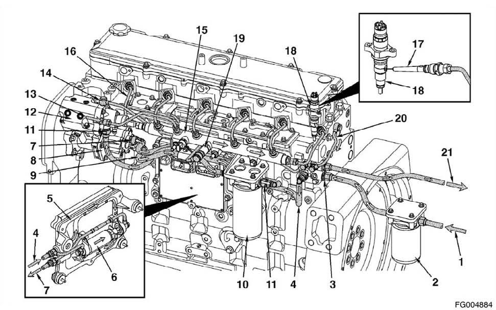
Cummins Common Rail Fuel System The Cummins Common Rail fuel system requires the use of two fuel filters. The suction side filter must have the following characteristics: • water-separating • 10-micron rating • water-drain valve • always chassis mounted. Fleetguard FS1003 meets these requirements. The pressure side filter must have the following characteristics: • 3-micron rating • engine mounted or chassis mounted. Fleetguard FF5580 meets these requirements. Refer to Section E for Engine Identification. The CM850 engine uses the Cummins Common Rail fuel system.
Remove
Disconnect the wiring harness from the fuel heater, if equipped as a option of pre-fuel filter. Loosen and remove the fuel filter. Make sure the seal ring does not stick to the filter head. Remove the ring with an O-ring pick, if necessary.
Figure 71
QSL9CumminsEng QSL9 Cummins Engine Page 75
It will be necessary to fill the 10-micron water stripping (suction side) fuel filter with fuel. Do not fill the 3-micron (pressure side) fuel filter with fuel before installation; instead, prime the fuel system using the fuel lift pump. Be sure the center seal ring is installed onto the filter spud. Install the filter as specified by the filter manufacturer. Connect fuel heater, if equipped as a option of pre-fuel filter.
CAUTION!
Mechanical overtightening can distort the threads and damage the filter seal or filter canister.
Prime
WARNING!
Do not open the high-pressure fuel system with the engine running. Engine operation causes high fuel pressure. Highpressure fuel spray can cause serious injury or death.
Cycle the starter switch and allow the lift pump to run. The lift pump will run for 30 seconds. Afterwards, turn the starter switch off and back on again allowing the lift pump to run again. Allow the lift pump to run for three or four 30-second cycles before attempting to start the engine.
Finishing Steps
Operate the fuel lift pump to help prime the fuel system. Turn the starter switch to RUN, but do not attempt to start the engine. This will cause the ECM to operate the fuel lift pump through a priming cycle which lasts at least 30 seconds. Cycle the lift pump several times by keying off, waiting 10 seconds and keying back on again. Once the engine is started, slowly increase the engine speed while air is purged from the fuel plumbing.
Figure 72
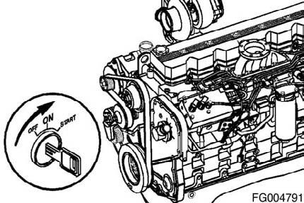
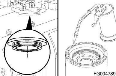
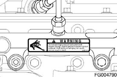
Figure 73
Figure 74
QSL9 Cummins Engine Page 76 QSL9CumminsEng
Drain
WARNING!
To reduce the possibility of personal injury, avoid direct contact of hot oil with your skin.
WARNING!
Some state and federal agencies have determined that used engine oil can be carcinogenic and cause reproductive toxicity. Avoid inhalation of vapors, ingestion, and prolonged contact with used engine oil. If not reused, dispose of in accordance with local environmental regulations.
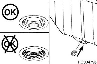
NOTE: Use a container that can hold at least 30 liters of lubricating oil. NOTE: For composite oil pans, hold the external locking nut in position with a separate wrench while removing the drain plug. This will prevent the bulkhead from loosening during drain plug removal. Operate the engine until the coolant temperature reaches 60°C [140°F]. Shut off the engine. Remove the oil drain plug. Drain the oil immediately to make sure all the oil and suspended contaminants are removed from the engine.
Remove
Clean the area around the lubricating oil filter head. Using an oil filter wrench, remove the filter. Clean the gasket surface of the filter head with a clean lint free cloth.
Figure 75
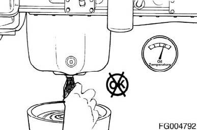
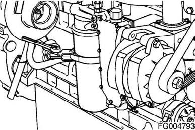
Figure 76
QSL9CumminsEng QSL9 Cummins Engine Page 77
CAUTION!
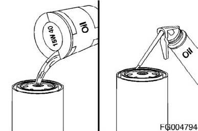
The lubricating oil filter should be full of oil at start-up to prevent engine damage.
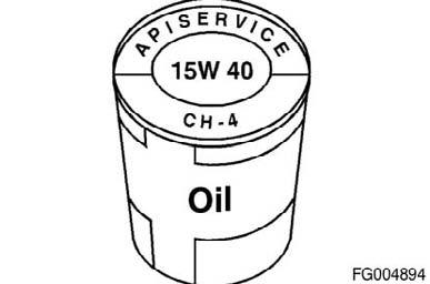
Use clean 15W-40 oil to coat the gasket surface of the filter. Fill the filter with clean 15W-40 oil.
Install the filter on the oil filter head. Tighten the filter until the gasket contacts the filter head surface. Tighten the filter according to the instructions supplied with the filter.
Clean and check the lubricating oil drain plug threads and sealing surface. Install the lubricating oil pan drain plug.
Figure 77
CAUTION!
Mechanical overtightening of the filter can distort the threads or damage the filter seal.

Figure 78
CAUTION!
For composite oil pans, always use a new sealing washer on the oil drain plug. Hold the external locking nut in place while tightening the oil drain plug.
Torque Value
Steel Oil Pan 80Nm 59 [ft-lb] Cast Aluminum Oil Pan 60Nm 45 [ft-lb]
Composite Oil Pan 60Nm 45 [ft-lb]
Figure 79
QSL9 Cummins Engine Page 78 QSL9CumminsEng
Fill
NOTE: Use a high quality 15W-40 multi viscosity oil, such as Cummins Premium BlueTM, or equivalent, in Cummins engines. Choose the correct oil for your operating climate as outlined in the Operation and Maintenance Manual.
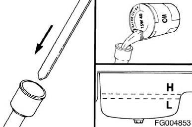
Fill the engine with clean lubricating oil to the proper level. NOTE: When filling the oil pan, use the fill tube on the side of the engine rather than on top of the rocker lever cover.
WARNING!
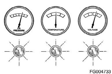
If no oil pressure is noted within 15 seconds after the engine is started, shut down the engine to reduce the possibility of internal damage.
Idle the engine to inspect for leaks at the drain plug.
Shut off the engine. Wait approximately 10 minutes to let the oil drain from the upper parts of the engine. Check the level again. Add oil as necessary to bring the oil level to the "H" (high) mark on the dipstick.
Figure 80
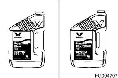
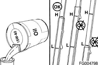
Figure 81
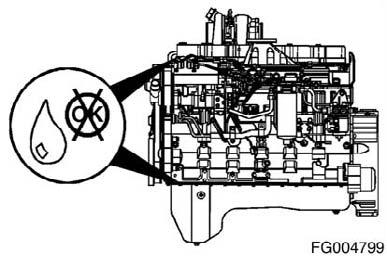
Figure 82

Figure 83
QSL9CumminsEng QSL9 Cummins Engine Page 79
Maintenance Check
Supplemental Coolant Additive (SCA) Check the SCA concentration level: At least twice a year At every subsequent oil drain interval if the concentration is above 3 units Whenever coolant is added to the cooling system between filter changes. Use Fleetguard coolant test kit, Part No. CC2602, to check the SCA concentration level. Instructions are included with the test kit. Refer to Coolant Recommendations and Specifications in Maintenance Specifications (Section V) for the correct SCA and antifreeze level. Antifreeze
Check the antifreeze concentration. Use a mixture of 50- percent water and 50-percent ethylene glycol or propylene glycol-based antifreeze to protect the engine to -32°C [-26°F] year-around. The Fleetguard refractometer, Part Number C2800, provides a reliable, easy-to-read, and accurate measurement of freezing point protection and glycol (antifreeze) concentration. Antifreeze is essential in every climate. Antifreeze broadens the operating temperature range by lowering the coolant freezing point and by raising its boiling point. The corrosion inhibitors also protect the cooling system components from corrosion and prolong component life.
CAUTION!
Over concentration of antifreeze or use of high-silicate antifreeze can damage the engine. Figure 84
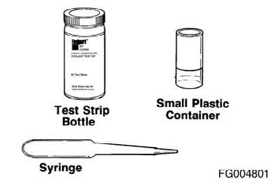
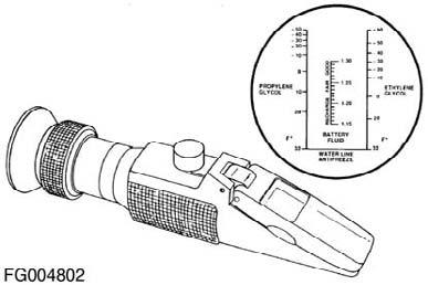
Figure 85
QSL9 Cummins Engine Page 80 QSL9CumminsEng
Remove
WARNING!
Do not remove the pressure cap from a hot engine. Wait until the coolant temperature is below 50°C [120°F] before removing the pressure cap. Heated coolant spray or steam can cause personal injury.
NOTE: Some engine models do not require coolant filters. Remove the coolant system pressure cap. Turn the shutoff valve to the OFF position by rotating the knob from vertical to horizontal in the direction shown.
WARNING!
A small amount of coolant can leak when servicing the coolant filter with the shutoff valve in the OFF position. To reduce the possibility of personal injury, avoid contact with hot coolant.
WARNING!
Coolant is toxic. Keep away from children and pets. If not reused, dispose of in accordance with local environmental regulations.
Remove and discard the coolant filter.
Install
CAUTION!
Do not allow oil to get into the filter. Oil will damage the DCA.
CAUTION!
Mechanical overtightening can distort the threads or damage the filter head. Figure 86
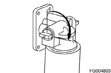
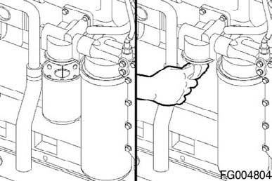
Figure 87
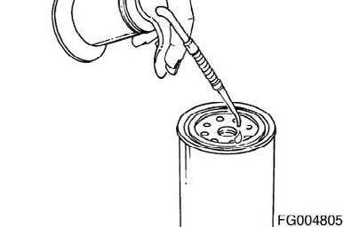
Figure 88
QSL9CumminsEng QSL9 Cummins Engine Page 81
Apply a thin film of lubricating oil to the gasket sealing surface before installing the new coolant filter. Install the coolant filter on the filter head. Tighten the filter until the gasket contacts the filter head surface. Tighten the coolant filter an additional 1/2 to 3/4 of a turn, or as specified by the filter manufacturer.
Turn the shutoff to the ON position by rotating the knob from horizontal to vertical in the direction shown.
Install the coolant system pressure cap.
Operate the engine and check for coolant leaks. After the air has been purged from the system, check the coolant level again.
CAUTION!
The valve must be in the ON position to prevent engine damage.
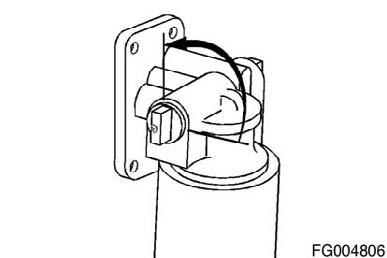
Figure 89
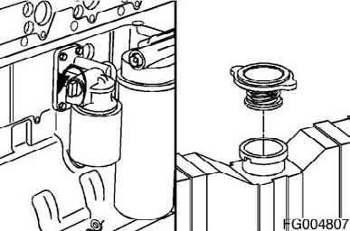
Figure 90
WARNING!
Do not remove the pressure cap from a hot engine. Wait until the coolant temperature is below 50°C [120°F] before removing the pressure cap. Heated coolant spray or steam can cause personal injury.
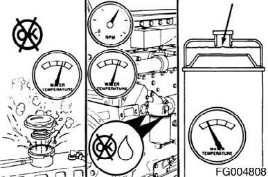
Figure 91
QSL9 Cummins Engine Page 82 QSL9CumminsEng
Inspect
Use an inductive charging and cranking system analyzer to loadtest the state of charge of maintenance-free batteries. If the state of charge is low, use a battery charger to charge the battery. Refer to the manufacturer's instructions. Replace the battery if it will not charge to the manufacturer's specifications or the battery will not maintain a charge.
If conventional batteries are used, remove the cell caps or covers and check the electrolyte (water and sulfuric acid solution) level.
WARNING!
Batteries can emit explosive gas. To reduce the possibility of personal injury, always ventilate the compartment before servicing the batteries. To reduce the possibility of arcing, remove the battery (-) negative cable first and attach the battery negative cable last.
NOTE: Maintenance-free batteries are sealed and do not require the addition of water. Fill each battery cell with water. Refer to the manufacturer's specifications. Refer to the accompanying table to determine the battery state of charge based on the specific-gravity readings.
Battery State of Charge Specific Gravity@ 27°C [80°F]
100% 1.260 to 1.280 75% 1.230 to 1.250 50% 1.200 to 1.220 25% 1.170 to 1.190 Discharged 1.110 to 1.130
Figure 92
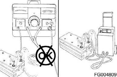

Figure 93
QSL9CumminsEng QSL9 Cummins Engine Page 83
Use a hydrometer to measure the specific gravity of each cell. NOTE: If the specific gravity of any cell is below 1.200, the battery must be charged. NOTE: Do not attempt to check the specific gravity of a battery immediately after adding water. If it is necessary to add water to allow use of the hydrometer, charge the battery several minutes at a high rate to mix the electrolyte.
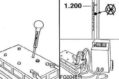
Figure 94
Battery Cables and Connections
Initial Check
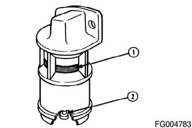
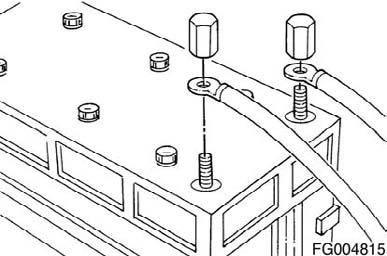
There are two possible heavy-duty battery connections: • Battery terminal and clamp (1) • Threaded battery terminal and nut (2).
Remove and inspect the battery cables and connections for cracks or corrosion. Replace broken terminals, connectors, or cables. If the connections are corroded, use a battery brush or wire brush to clean the connections until shiny. Make sure all debris is removed from the connecting surfaces.
WARNING!
Batteries can emit explosive gases. To reduce the possibility of personal injury, always ventilate the compartment before servicing the batteries. To reduce the possibility of arcing, remove the negative (-) battery cable first and attach the negative (-) battery cable last.
QSL9 Cummins Engine Page 84 Figure 95
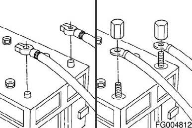
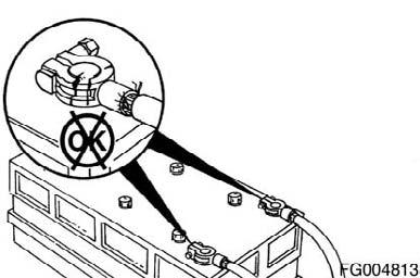
Figure 96
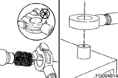
Figure 97
QSL9CumminsEng
Batteries can emit explosive gases. To reduce the possibility of personal injury, always ventilate the compartment before servicing the batteries. To reduce the possibility of arcing, remove the negative (-) battery cable first and attach the negative (-) battery cable last.
Install the cables and tighten the battery connections. Coat the terminals with grease to prevent corrosion.
Figure 98
QSL9CumminsEng QSL9 Cummins Engine Page 85
MAINTENANCE PROCEDURES AT 1,000 HOURS OR 1 YEAR
Maintenance Procedures - Overview
General Information
All maintenance checks and inspections listed in previous maintenance intervals must also be performed at this time, in addition to those listed under this maintenance interval.
Drive Belts
Maintenance Check
Poly-Vee Belt Inspect the belts daily. Check the belt for intersecting cracks. Traverse (across the belt width) cracks are acceptable. Longitudinal (direction of belt length) cracks that intersect with transverse cracks are not acceptable. Replace the belt if it is frayed or has pieces of material missing. Refer to Section A for belt adjustment and replacement procedures. Belt damage can be caused by: • Incorrect tension • Incorrect size or length • Pulley misalignment • Incorrect installation • Severe operating environment • Oil or grease on the side of belts. Measure the belt tension in the center span of the pulleys. Refer to the Belt Tension Chart in Section V for the correct gauge and tension value for the belt width used. An alternate method (deflection method) can be used to check belt tension by applying 110 N [25 lbf] force between the pulleys on v-belts. If the deflection is more than one belt thickness per foot of pulley center distance, the belt tension must be adjusted. Refer to Section A for adjustment procedures.
Figure 99
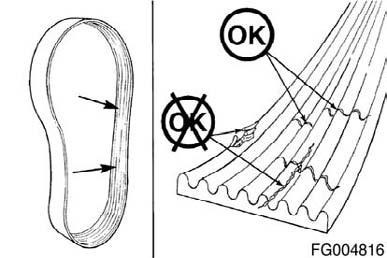
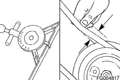
Figure 100
QSL9 Cummins Engine Page 86 QSL9CumminsEng
Maintenance Check Remove the drive belt.
NOTE: The fan hub must rotate without any wobble or excessive end play. Check the fan hub bearing.
Fan Hub End Play
Max. 0.15mm Max. 0.006 in
Figure 101
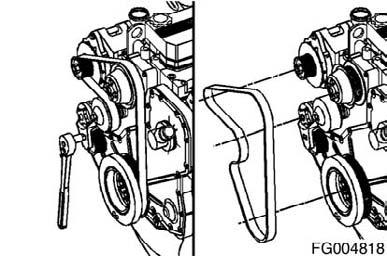
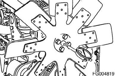
Figure 102
Drive Belt, Cooling Fan
Remove
Lift the tensioner to remove the drive belt. NOTE: The belt tensioner is spring-loaded and must be pivoted away from the drive belt. Pivoting in the wrong direction can result in damage to the belt tensioner.
Install
Lift and hold the belt tensioner. Install the drive belt and release the tensioner. NOTE: The belt tensioner is spring-loaded and must be pivoted away from the drive belt. Pivoting in the wrong direction can result in damage to the belt tensioner. Service Tip: If difficulty is experienced installing the drive belt (i.e., the belt seems too short), position the belt over the grooved pulleys first then while holding the tensioner up, slide the belt over the water pump pulley.
Figure 103
QSL9CumminsEng QSL9 Cummins Engine Page 87
Inspect for Reuse
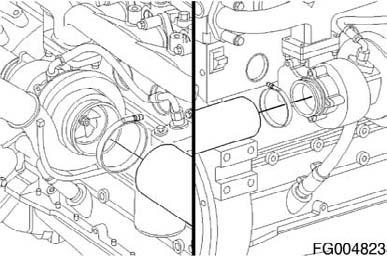
Remove the intake pipe from the turbocharger. Inspect the turbocharger compressor impeller blades for damage. Replace the turbocharger if damage is found. Contact your authorized dealer and a Cummins Authorized Repair Location for replacement.
If the compressor impeller is damaged, inspect the intake piping and filter for damage. Repair any damage before operating the engine.
Remove the exhaust pipe from the turbocharger. Inspect the turbine wheel for damage. Replace the turbocharger if damage is found. Contact a Cummins Authorized Repair Location for replacement.
Install the intake pipe and tighten the clamp. Install the exhaust pipe and tighten the clamp. Torque Value: 8 Nm [71 in-lb]
Figure 104
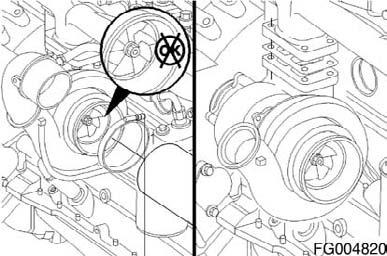

Figure 105
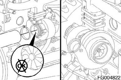
Figure 106