39 minute read
Operating Instructions

Operating Instructions - Overview
Correct care of your engine will result in longer life, better performance, and more economical operation. Follow the daily maintenance checks listed in Maintenance Guidelines (Section 2). The new Cummins engine associated with this manual does not require a "break-in" procedure. This section of the manual provides all of the necessary information required for proper engine operation. Check the oil pressure indicators, temperature indicators, warning lights, and other gauges daily to make sure they are operational.
WARNING!
DO NOT OPERATE A DIESEL ENGINE WHERE THERE ARE OR CAN BE COMBUSTIBLE VAPORS. The vapors can be sucked through the air intake system and cause engine acceleration and overspeeding that can result in a fire, an explosion, and extensive property damage. Numerous safety devices are available, such as air intake shutoff devices, to minimize the risk of overspeeding where an engine, due to its application, due to a fuel spill or gas leak. Remember, Cummins has no way of knowing the use you have for your engine. THE EQUIPMENT OWNER AND OPERATOR ARE RESPONSIBLE FOR SAFE OPERATION IN A HOSTILE ENVIRONMENT. CONSULT YOUR CUMMINS AUTHORIZED REPAIR LOCATION FOR FURTHER INFORMATION. Figure 15
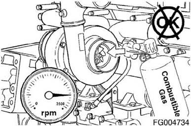
Figure 16
QSL9CumminsEng QSL9 Cummins Engine Page 37
Cummins recommends the installation of an air intake shutoff device or a similar safety device to minimize the risk of overspeeding where an engine, due to the vehicle, vessel or equipment being operated in a combustible environment, such as due to a fuel spill or gas leak.
CAUTION!
Do not expose the engine to corrosive chemicals. Corrosive chemicals can damage the engine.
Normal Starting Procedure
CAUTION!
The engine must have adequate oil pressure within 15 seconds after starting. If the WARNING light indicating low oil pressure has not gone out or there is no oil pressure indicated on a gauge within 15 seconds, shut off the engine immediately to avoid engine damage. The low oil pressure troubleshooting procedure is located in Troubleshooting Symptoms (Section TS).
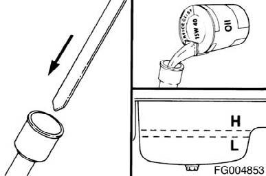
Idle the engine 3 to 5 minutes before operating with a load.
After starting a cold engine, increase the engine speed (rpm) slowly to provide adequate lubrication to the bearings and to allow the oil pressure to stabilize.
QSL9 Cummins Engine Page 38 Figure 17
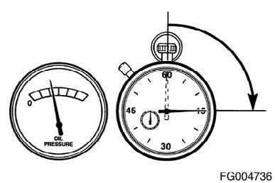
Figure 18
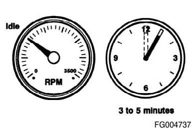
Figure 19
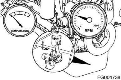
Figure 20
QSL9CumminsEng
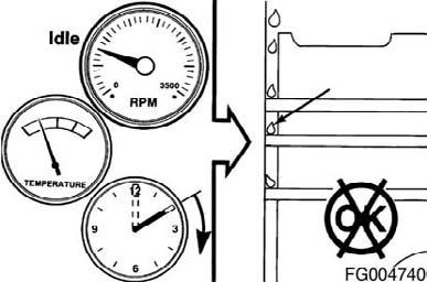
Do not operate engine at low idle for long periods with engine coolant temperature below the minimum specification in Maintenance Specifications (Section V). This can result in the following: • Fuel Dilution of the lubricating oil • Carbon build up in the cylinder • Cylinder head valve sticking • Reduced performance Figure 21
Cold Weather Starting
General Information
Follow the Normal Starting Procedures in this section. In cold weather, the Wait-To-Start light will stay on longer.
Using Starting Aids
WARNING!
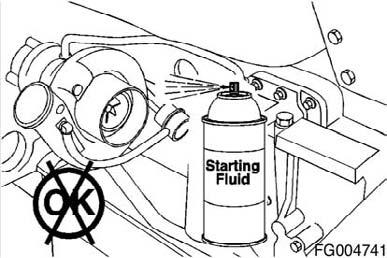
Do not use starting fluids with this engine. This engine is equipped with an intake air heater; use of starting fluid can cause an explosion, fire, personal injury, severe damage to the engine and property damage.
Cold weather starting aids are available for your engine. Contact the local Cummins Authorized Repair Location for more information.
Figure 22
Starting Procedure After Extended
Shutdown or Oil Change
Follow the Normal Starting Procedure in this section. The engine will not start until the minimum cranking oil pressure is detected by the ECM. It can take more cranking time to start the engine after an extended shut down or oil change.
QSL9CumminsEng QSL9 Cummins Engine Page 39
Normal
If equipped, monitor the oil pressure and coolant temperature gauges frequently. Refer to Lubricating Oil System specifications and Cooling System specifications, in Maintenance Specifications (Section V) for recommended operating pressures and temperatures. Shut off the engine if any pressure or temperature does not meet the specifications. Continuous operation with engine coolant temperature above or below the engine coolant temperature specifications listed in Maintenance Specifications (Section V) can damage the engine. If an overheating condition starts to occur, reduce the power output of the engine by releasing the accelerator pedal or lever or shifting the transmission to a lower gear, or both, until the temperature returns to the normal operating range. If the engine temperature does not return to normal, shut off the engine, and refer to Troubleshooting Symptoms (Section TS), or contact a Cummins Authorized Repair Location.
Most failures give an early warning. Look and listen for changes in performance, sound, or engine appearance that can indicate service or engine repair is needed. Some changes to look for are:
• Engine misfires • Vibration • Unusual engine noises • Sudden changes in engine operating temperatures or pressures • Excessive smoke • Loss of power • An increase in oil consumption • An increase in fuel consumption • Fuel, oil, or coolant leaks.
Cold Weather
It is possible to operate engines in extremely cold environments if they are properly prepared and maintained. Satisfactory performance of an engine in low ambient temperature conditions requires modification of the engine, surrounding equipment, operating practices and maintenance procedures.
Figure 23
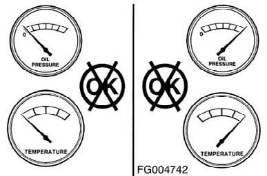
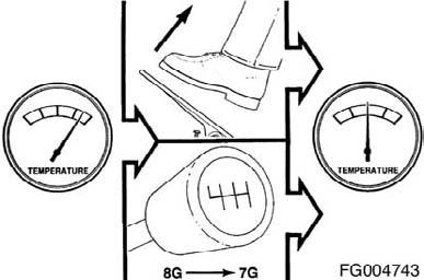
Figure 24
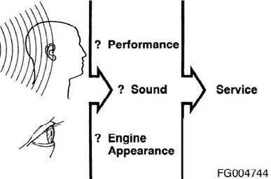
Figure 25
QSL9 Cummins Engine Page 40 QSL9CumminsEng
The correct engine coolant lubricating oil and fuels must be used for the cold weather range in which the engine is being operated. Below are the recommendations for these critical engine fluids:
Ambient Temperature
0 to -32°C [32 to -25°F] Use 50-percent ethylene glycol antifreeze and 50-percent water for the engine coolant mixture. Refer to Maintenance Specifications (Section V) Lubricating Oil recommendations for the correct specifications. The Diesel fuel must have maximum cloud and pour points 6°C [10°F] lower than the ambient temperature in which the engine operates.
-32 to -54°C [-25 to -65°F] Use 60-percent ethylene glycol antifreeze and 40-percent water for the engine coolant mixture. Refer to Maintenance Specifications (Section V) Lubricating Oil recommendations for the correct specifications. The Diesel fuel must have maximum cloud and pour points 6°C [10°F] lower than the ambient temperature in which the engine operates. The following cold weather operating aids are required for cold weather situations:
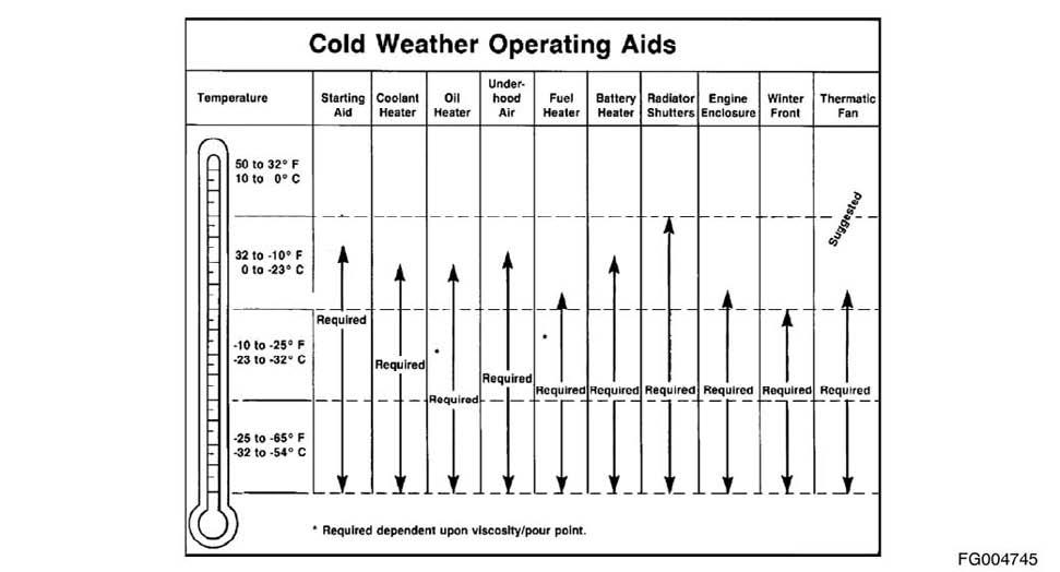
Figure 26
QSL9CumminsEng QSL9 Cummins Engine Page 41
CAUTION!
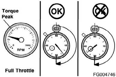
Do not operate the engine at full throttle operation below peak torque rpm (refer to engine data plate for peak torque rpm) for more than 30 seconds. Operating the engine at full throttle below peak torque will shorten engine life to overhaul, can cause serious engine damage, and is considered engine abuse.
Cummins engines are designed to operate successfully at full throttle under transient conditions down to peak torque engine speed. This is consistent with recommended operating practices.
CAUTION!
Do not operate the engine beyond the maximum engine speed. Operating the engine beyond the maximum engine speed can cause severe engine damage. Use proper operating techniques for the vehicle, vessel, or equipment to prevent engine overspeed. The maximum engine speed specification is listed in Maintenance Specifications (Section V). Figure 27
Engine Shutdown
Allow the engine to idle 3 to 5 minutes before shutting it off after a full-load operation. This allows adequate cool down of pistons, cylinders, bearings, and turbocharger components. Turn the ignition starter switch to the OFF position. If the engine does not shut down, refer to Troubleshooting Symptom (Section TS).
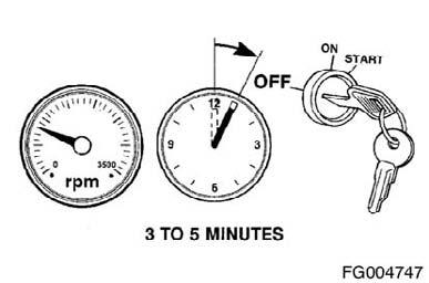
Figure 28
QSL9 Cummins Engine Page 42 QSL9CumminsEng
General Information
The QSL9 engine control system is electronically controlled and also provides many operator and vehicle or equipment features. The base functions of the control system include fueling and timing control, limiting the engine speed operating range between the low- and high-idle set points, and reducing exhaust emissions while optimizing engine performance.
The control system uses inputs from the operator and engine sensors to determine the fueling and timing required to operate at the desired engine speed. The electronic control module (ECM) is the control center of the system. It processes all of the inputs and sends commands to the fuel system, vehicle, and engine control devices.
The electronic control module (ECM) performs diagnostic tests on most of its circuits and will activate a fault code if a problem is detected in one of these circuits. Along with the fault code identifying the problem, a snapshot of engine operating parameters at the time of fault activation is stored in memory. Most fault codes will activate a diagnostic light to signal the driver.
The ECM communicates with service tools and other vehicle controllers such as the transmission and fan controller through an SAE J1939 data link. Some vehicles and equipment will have J1939 networks that link many of the "smart" controllers together. Vehicle control devices can temporarily command engine speed or torque to perform one of its functions such as transmission shifting.
Figure 29
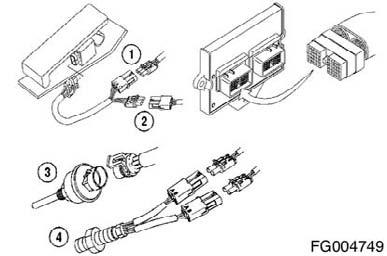
Figure 30
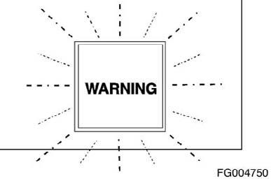
Figure 31
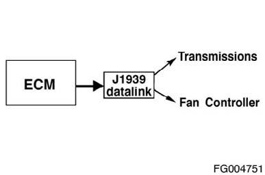
Figure 32
QSL9CumminsEng QSL9 Cummins Engine Page 43
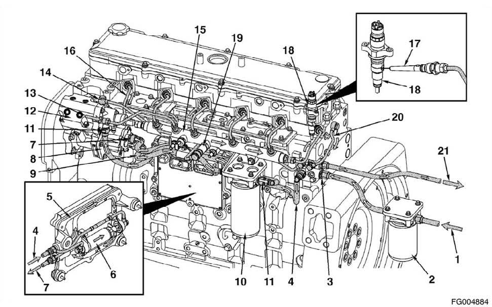
The following inputs are provided by original equipment manufacturer (OEM)-selected devices:
Reference Number Description
1 Coolant Temperature Sensor 2 Oil Pressure Sensor 3 Water-in-Fuel Sensor 4 Intake Air Temperature Sensor 5 Intake Manifold Pressure Sensor 6 Engine Speed and Position Sensors 7 Common Rail Pressure Sensor 8 Injection Control Valve 9 Pumping Control Valves
Reference Number Description
1 Accelerator pedal position sensor 2 Idle validation switch 3 Coolant level sensor 4 Vehicle speed sensor
NOTE: These inputs are application-dependent. Some applications will not use all of these inputs.
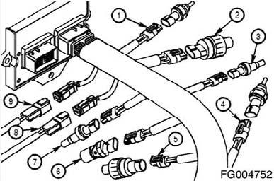
Figure 33
Figure 34
Engine Protection System
CAUTION!
When the red STOP light is illuminated, the driver must pull to the side of the road, once it is safe to do so, to reduce the possibility of engine damage.
The QSL9 engines are equipped with an engine protection system. The system monitors critical engine temperatures and pressures, and will log diagnostic faults when an over or under normal operation condition occurs. If an out-of-range condition exists, and engine derate action is to be initiated, the operator will be alerted by an in-cabin WARNING light. The WARNING light will blink or flash when outof-range conditions continue to get worse.
QSL9 Cummins Engine Page 44 Figure 35
QSL9CumminsEng
When the red STOP light is illuminated, the driver must pull to the side of the road, when it is safe to do so, to reduce the possibility of engine damage. The engine protection system monitors the following data: • Coolant temperature • Coolant level (optional) • Oil pressure • Intake manifold temperature • Engine overspeed • Fuel temperature. • OEM pressure (optional) NOTE: Engine power and speed will gradually reduce depending on the severity of the observed condition. The engine protection system will not shut down the engine unless the engine protection shutdown feature has been enabled. Engine Protection Shutdown This feature automatically shuts off the engine when the temperature, pressure, or coolant level sensors indicate the engine is operating over or under normal operating conditions. The red "STOP" light in the cabin will flash for 30 seconds before shutdown to alert the driver. The engine protection shutdown feature can be enabled or disabled using the INSITETM‚electronic service tool if the feature is available in the calibration.
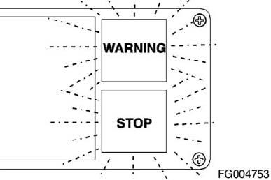
Figure 36
Programmable Features
The electronic control system can provide many features that are integrated into the vehicle's operation. Some of these features can be adjusted or turned on and off with a service tool, but some are set at the factory and cannot be changed. The following section describes the functionality of each feature and whether an available feature in a given application is calibration-dependent.
Figure 37
QSL9CumminsEng QSL9 Cummins Engine Page 45
Using the INSITETM service tool, the following maintenance data can be viewed or printed from the ECM: • Percent of current interval consumed (by time or fuel burned) • Time since last reset • Fuel burned since last reset • Current maintenance monitor mode.
Maintenance Monitor Reset Log The maximum threshold is entered by the user either directly using the time mode, or by entering the interval factor in the automatic mode. The adjusted threshold is the new threshold set automatically by the maintenance monitor when the automatic mode is selected, and it automatically reduces the maintenance intervals. The "interval reset at" is the interval time and fuel recorded by the ECM at the time the maintenance monitor was reset.
The "cumulative reset at" is the total time and fuel recorded by the ECM at the time the maintenance monitor was reset. The possible error will contain an "X" next to a row of data that can be inaccurate due to a system fault. The "X" will be triggered when a vehicle speed sensor fault or power down fault occurs. These faults can cause data to either not accumulate or accumulate inaccurately.
Maintenance Monitor Reset The maintenance monitor reset can be accomplished by clicking the reset button on the maintenance monitor screen using the INSITETM service tool, or using one of the following procedures: 1. Procedure for applications with a throttle pedal. A. Turn the starter switch to the ON position (but do not start the engine) and turn the diagnostic switch to the ON position. B. Fully depress the throttle pedal (100 percent) for at least 3 seconds and then release it. C. Fully depress the throttle pedal (100 percent), twice, for less than 3 seconds each time.
Figure 38
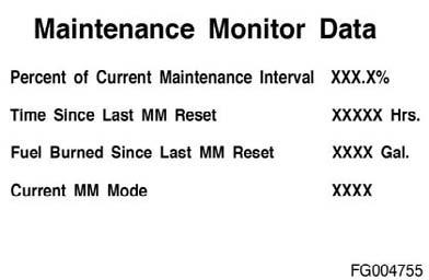
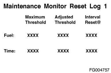
Figure 39
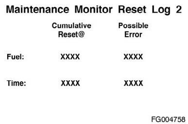
Figure 40
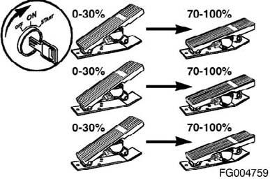
Figure 41
QSL9 Cummins Engine Page 46 QSL9CumminsEng
D. Fully depress the throttle pedal (100 percent) for at least 3 seconds and then release it. 2. Procedure for applications without a throttle pedal. A. Turn the starter switch to the ON position (but do not start the engine). B. Turn the diagnostic switch to the ON position for at least 3 seconds and then turn it to the OFF position. C. Turn the diagnostic switch to the ON position (for less than 3 seconds) and then to the OFF position, twice, with less than 3 seconds between each switching. D. Turn the diagnostic switch to the ON position for at least 3 seconds and then turn it to the OFF position. NOTE: Procedure must be completed within 20 seconds after initiating steps 1) a through d or steps 2) a through d or the data will not reset. NOTE: The WARNING light will flash three times to indicate that the reset has been completed. Trip Information System The trip information system records fuel consumption and time information for the engine during normal operation, and in certain operating modes such as intermediate speed control and idle. Either data can be displayed using the INSITETM‚service tool. Some data cannot be reset and reflect the performance of the engine over its lifetime. Other data, and trip data, can be reset using the INSITETM service tool.
Duty Cycle Monitor With this feature the ECM tracks engine load and speed. These data are stored in the ECM, and the INSITETM electronic service tool is used to display the data. The INSITETM electronic service tool display shows a duty cycle "map" that shows the whole engine's operating range in terms of speed and load. This "map" is divided into fifty regions. The percent of the engine operating time spent in each region is shown on the display. The ECM contains duty cycle data for the whole life of the engine and for two 500-hour operating periods. The two 500hour maps can be reset with the INSITETM service tool. Low-Idle Speed This parameter is the engine speed at which the engine will idle. This speed can be adjusted by a cabin switch if the switch is installed and the low-idle adjustment feature is enabled. Low-idle speed can be adjusted using the INSITETM service tool.
Figure 42


Figure 43
QSL9CumminsEng QSL9 Cummins Engine Page 47
Low-Idle Adjustment This feature allows the idle speed range to be increased or decreased in 25-rpm standard increments with the in cabin increment or decrement switch. Depending on the calibration, the rpm increment could not be 25-rpm. There are limits on how high or low the low-idle speed can be adjusted. The allowable adjustment range for a QSL9 engine is 800 to 1200 rpm. Alternate Low-Idle Speed Control This feature allows the operator to switch between the low idle speed setting (3) and an alternate low-idle speed setting (4) (the axis 1 is engine speed and 2 is engine torque). NOTE: On QSL9 engines during cold start-ups, and with engine temperatures less than 21°ýC [70°ýF], pilot injection has priority over alternate low-idle speed until the engine is properly warmed up.
Depending on original equipment manufacturer (OEM) availability the alternate low-idle speed control feature provides the ability to select an alternate idle speed by an original equipment manufacturer (OEM)-provided switch (1 is in the OFF position, and 2 is in the ON position). NOTE: The alternate low idle speed cannot be adjusted by the idle increment/decrement switch.
Engine Time Offset This parameter is part of the trip information system. The value entered here will be added to total ECM time to get total engine time. This parameter allows the time on the engine to be entered when an ECM is replaced. Engine time offset can be adjusted using the INSITETM service tool.
Figure 44
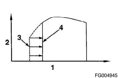
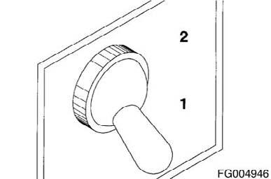
Figure 45
Figure 46
QSL9 Cummins Engine Page 48 QSL9CumminsEng
Real-Time Clock The real-time clock provides time and date for stamping of operational events. The real time clock will maintain time value in units of year, month, day, hour (24-hour base), minute, and second. Loss of clock accuracy will be indicated with a diagnostic fault code. This feature can be set manually or automatically (to the PC time and date) through the INSITETM service tool.
Reduced accuracy will be indicated with the diagnostic Fault Code 319. Upon loss of clock accuracy, the real-time clock will be "initialized" with the last known real time. The loss of the real-time clock can occur due to a hardware failure (real-time clock chip fails) or a loss of power. There is no battery backup for the clock. Therefore, if the battery is removed from the system for five seconds, the real-time clock will be lost. To reinitialize the real-time clock, use the INSITETM service tool, the menu item "Adjustments - Feature and Parameters." At this point a screen will pop up in which you can manually enter a new time and date, or you can select "Real-Time Clock Autoset" and the time and date will be set to the PC's time and date. After reinitializing the real time clock, INSITETM electronic service tool will set the Fault Code 319 inactive. NOTE: Once the real-time clock has been enabled, you cannot disable the feature.
Auto Set (set to PC time and date) No __ Yes __ No
Manual Date ____ ____
Date __/__/__ Adjust Date
Time __/__/__
Adjust Time Standard Setting Customer Selection
Diagnostic Fault Codes
The QSL9 control system can show and record operation anomalies that present themselves as fault codes. These codes will make troubleshooting easier. The fault codes are recorded in the electronic control module (ECM). They can be read using the fault lights in the dash or with the INSITETM service tool. NOTE: Not all engines or QSL9 control system anomalies are shown as fault codes.
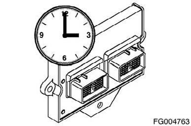
Figure 47
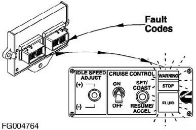
Figure 48
QSL9CumminsEng QSL9 Cummins Engine Page 49
There are two types of system codes: • Engine electronic control system fault codes • Engine protection system fault codes All fault codes recorded will be either active (fault code is currently active on the engine) or inactive (fault code was active at some time, but at the moment is not active).
Most, but not all, of the electronic fault codes will light a light when they are active. There are two possible lights that can be illuminated when a fault code is active: • The WARNING or CHECK ENGINE light is yellow and indicates the need to repair the fault at the first available opportunity. • The STOP or STOP ENGINE light is red and indicates the need to shut down engine as soon as it can be safely done. The engine should remain shut down until the fault can be repaired. 1. Fault Detection Faults are detected while the starter switch is on, during the operation of the machine itself. If an engine fault occurs, several actions are taken by the engine control system. First, the appropriate fault code is logged along with a snapshot of engine control parameters. The fault snapshot contains engine control data before and just after the fault occurrence. The second action taken is to illuminate the appropriate fault light for alerting the operator. In addition, the fault code is broadcast out over the J1939 data bus as port as part of the DM1 message. An operator response is expected to be taken when the fault either illuminates a light or is broadcast over J1939. 2. Flash Out of Fault Codes (All Industrial Applications without Cense) Fault flash out mode can be entered through the use of a diagnostic switch or the accelerator pedal. The following actions must be taken to activate the fault flashout. • Starter Switch ON • Engine not running, Engine Speed = 0 rpm • Diagnostic Switch ON When a diagnostic switch is used to enter fault flashout mode, the ECM will a automatically flash the first fault code after the switch is turned on. The (Idle or ISC) increment/ decrement switches are used to sequence forward or backwards through the active fault.
Figure 49
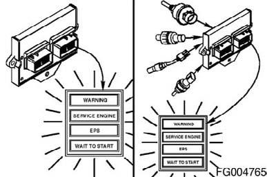
Figure 50
QSL9 Cummins Engine Page 50 QSL9CumminsEng
When the number has finished flashing in red, a yellow WARNING light will appear again. The fault code will repeat the same sequence. The lights flash each fault code out two times before advancing to the next code. To skip to the next fault code sooner, move the IDLE SPEED ADJUST switch (if equipped) momentarily to the (+) position. You can go back to the previous fault code by momentarily moving the IDLE SPEED ADJUST switch (if equipped) to the (-) position. If only one active fault code is recorded, the QSL control system will continuously display the same fault code, even when either (+) or (-) switch is depressed. 4. Fault Code Snapshot Data This additional fault code information can be obtained by using the INSITETM service tool. The snapshot data records the value or state of the control system sensors and switches at the time a fault code occurred. Either set of data is stored for the first occurrence of the fault, since it was last cleared, and for the most recent occurrence. This data can be very valuable when trying to recreate or determine engine operating conditions at the time of a fault.
NOTE: Connectors (B) are actually located on the outside of ECM and inside of electric box at the bottom of left-hand side in cabin.
Reference Number Description
1 A yellow WARNING light will flash. 2 There is a short 1- or 2-second pause. 3 The fault code will flash on the red STOP light. 4 There is a short 1- or 2-second pause between each number.
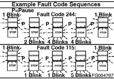
Figure 51
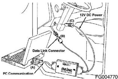
Figure 52
QSL9CumminsEng QSL9 Cummins Engine Page 51
Fault Code J1939 SPN J1939 FMI J1587 PID/SID J1587 FMI Light Color J1939 SPN Description Cummins Description
111 629 12 S254 12 Red Controller #1 Engine Control Module Critical internal failure - Bad intelligent Device or Component 115 612 2 P190 2 Red System Diagnostic Engine Speed/Position Sensor Circuit Code # 2 lost both of two signals from the magnetic pickup sensor - Data Erratic, Intermittent, or incorrect 122 102 3 P102 3 Amber Boost Pressure Intake Manifold Pressure Sensor Circuit - Voltage Above Normal, or Shorted to High Source 123 102 4 P102 4 Amber Boost Pressure Intake Manifold Pressure Sensor Circuit - Voltage Below Normal, or Shorted to Low Source
131 91 3 P91 3 Red Accelerator Pedal Position
Accelerator Pedal or Lever Position Sensor Circuit - Voltage Above Normal, or Shorted to High Source 132 91 4 P91 4 Red Accelerator Pedal Accelerator Pedal or Lever Position Position Sensor Circuit - Voltage Below Normal, or Shorted to Low Source 133 974 3 P29 3 Red Remote Accelerator Remote Accelerator Pedal or Lever Position Sensor Circuit - Voltage Above Normal, or Shorted to High Source 134 974 4 P29 4 Red Remote Accelerator Remote Accelerator Pedal or Lever Position Sensor Circuit - Voltage Below Normal, or Shorted to Low Source 135 100 3 P100 3 Amber Engine Oil Pressure Oil Pressure Sensor Circuit - Voltage Above Normal, or Shorted to High Source 141 100 4 P100 4 Amber Engine Oil Pressure Oil Pressure Sensor Circuit - Voltage Below Normal, or Shorted to Low Source 143 100 18 P100 1 Amber Engine Oil Pressure Oil Pressure Low - Data Valid but Below Normal Operational Range - Moderately Severe Level
144 110 3 P110 3 Amber Engine Coolant Temperature Coolant Temperature Sensor Circuit - Voltage Above Normal, or Shorted to High Source
QSL9 Cummins Engine Page 52 QSL9CumminsEng
Fault Code J1939 SPN J1939 FMI J1587 PID/SID J1587 FMI Light Color J1939 SPN Description Cummins Description
145 110 4 P110 4 Amber Engine Coolant Temperature Coolant Temperature Sensor Circuit? Voltage Below Normal, or Shorted to Low Source
146 110 16 P110 0 Amber Engine Coolant Temperature
147 91 1 P91 1 Red Accelerator Pedal Position Coolant Temperature High - Data Valid but Above Normal Operational Range - Moderately Severe Level Accelerator Pedal or Lever Position Sensor Circuit - Abnormal Frequency, Pulse Width, or Period
148 91 0 P91 0 Red Accelerator Pedal Position
151 110 0 P110 0 Red Engine Coolant Temperature
153 105 3 P105 3 Amber Intake Manifold #1 Temp
154 105 4 P105 4 Amber Intake Manifold #1 Temp
Accelerator Pedal or Lever Position Sensor Circuit - Abnormal Frequency, Pulse Width, or Period Coolant Temperature Low - Data Valid but Above Normal Operational Range - Most Severe Level Intake Manifold Air Temperature Sensor Circuit - Voltage Above Normal, or Shorted to High Source Intake Manifold Air Temperature Sensor Circuit - Voltage Below Normal, or Shorted to Low Source 155 105 0 P105 0 Red Intake Manifold #1 Intake Manifold Air Temperature High Temp - Data Valid but Above Normal Operational Range - Most Severe Level 187 1080 4 S232 4 Amber 5 Volts DC Supply Sensor Supply Voltage #2 Circuit - Voltage Below Normal, or Shorted to Low Source 195 111 3 P111 3 Amber Coolant Level Coolant Level Sensor Circuit - Voltage Above Normal, or Shorted to High Source 196 111 4 P111 4 Amber Coolant Level Coolant Level Sensor Circuit - Voltage Below Normal, or Shorted to Low Source 221 108 3 P108 3 Amber Barometric Pressure Barometric Pressure Sensor Circuit - Voltage Above Normal, or Shorted to High Source 222 108 4 P108 4 Amber Barometric Pressure Barometric Pressure Sensor Circuit - Voltage Below Normal, or Shorted to Low Source 227 1080 3 S232 3 Amber 5 Volts DC Supply Sensor Supply Voltage #2 Circuit - Voltage Above Normal, or Shorted to High Source 234 190 0 P190 0 Red Engine Speed Engine Speed High - Data Valid but Above Normal Operational Range - Most Severe Level
QSL9CumminsEng QSL9 Cummins Engine Page 53
Fault Code J1939 SPN J1939 FMI J1587 PID/SID J1587 FMI Light Color J1939 SPN Description Cummins Description
235 111 1 P111 1 Red Coolant Level Coolant Level Low - Data Valid but Below Normal Operational Range - Most Severe Level 237 644 2 S30 2 Amber External Speed Input (Multiple Unit Synchronization) - Data Erratic, Intermittent, or Incorrect
238 611 4 S232 4 Amber System Diagnostic code # 1 Sensor Supply Voltage #3 Circuit? Voltage Below Normal, or Shorted to Low Source
241 84 2 P84 2 Amber Wheel-based Vehicle Speed 242 84 10 P84 10 Amber Wheel-based Vehicle Speed
245 647 4 S33 4 Amber Fan Clutch Output Device Driver 249 171 3 P171 3 Amber Ambient Air Temperature
256 171 4 P171 4 Amber Ambient Air Temperature Vehicle Speed Sensor Circuit - Data Erratic, Intermittent, or Incorrect Vehicle Speed Sensor Circuit tampering has been detected Abnormal Rate of Change Fan Control Circuit - Voltage Below Normal, or Shorted to Low Source Ambient Air Temperature Sensor Circuit - Voltage Above Normal, or Shorted to High Source Ambient Air Temperature Sensor Circuit - Voltage Below Normal, or Shorted to Low Source
268 94 2 P94 2 Amber Fuel Delivery Pressure Fuel Pressure Sensor Circuit - Data Erratic, Intermittent, or Incorrect
271 1347 4 S126 4 Amber Fuel Pump Pressurizing Assembly #1 272 1347 3 S126 3 Amber Fuel Pump Pressurizing Assembly #1 275 1347 7 S126 7 Amber Fuel Pump Pressurizing Assembly #1 281 1347 7 S126 7 Amber Fuel Pump Pressurizing Assembly #1
High Fuel Pressure Solenoid Valve Circuit - Voltage Below Normal, or Shorted to Low Source High Fuel Pressure Solenoid Valve Circuit? Voltage Above Normal, or Shorted to High Source Fuel Pumping Element (Front) - Mechanical System Not Responding Properly or Out of Adjustment High Fuel Pressure Solenoid Valve #1 - Mechanical System Not Responding Properly or Out of Adjustment 284 1043 4 S221 4 Amber Internal Sensor Engine Speed/Position Sensor Voltage Supply (Crankshaft) Supply Voltage Circuit - Voltage Below Normal, or Shorted to Low Source 285 639 9 S231 9 Amber SAE J1939 Data Link SAE J1939 Multiplexing PGN Timeout Error - Abnormal Update Rate
QSL9 Cummins Engine Page 54 QSL9CumminsEng
Fault Code J1939 SPN J1939 FMI J1587 PID/SID J1587 FMI Light Color J1939 SPN Description Cummins Description
286 639 13 S231 13 Amber SAE J1939 Data Link SAE J1939 Multiplexing Configuration Error - Out of Calibration 287 91 19 P91 Red Accelerator Pedal SAE J1939 Multiplexing Accelerator Position Pedal or Lever Sensor System Error - Received Network Data In Error 288 974 19 P29 Red Remote Accelerator SAE J1939 Multiplexing Remote Accelerator Pedal or Lever Data Error - Received Network Data In Error 293 441 3 P441 3 Amber OEM Temperature Auxiliary Temperature Sensor Input # 1 Circuit - Voltage Above Normal, or Shorted to High Source 294 441 4 P441 4 Amber OEM Temperature Auxiliary Temperature Sensor Input # 1 Circuit - Voltage Below Normal, or Shorted to Low Source 295 108 2 P108 2 Amber Barometric Pressure Barometric Pressure Sensor Circuit - Data Erratic, Intermittent, or Incorrect 297 1388 3 P223 3 Amber Auxiliary Pressure Sensor Input # 2 Circuit - Voltage Above Normal, or Shorted to High Source 298 1388 4 P223 4 Amber Auxiliary Pressure Sensor Input # 2 Circuit - Voltage Below Normal, or Shorted to Low Source 319 251 2 P251 2 Maint Real Time Clock Power Interrupt - Data Erratic, Intermittent, or Incorrect 322 651 5 S1 5 Amber Injector Cylinder #01 Injector Solenoid Cylinder #1 Circuit? Current Below Normal, or Open Circuit 323 655 5 S5 5 Amber Injector Cylinder #05 Injector Solenoid Cylinder #5 Circuit? Current Below Normal, or Open Circuit 324 653 5 S3 5 Amber Injector Cylinder #03 Injector Solenoid Cylinder #3 Circuit? Current Below Normal, or Open Circuit 325 656 5 S6 5 Amber Injector Cylinder #06 Injector Solenoid Cylinder #6 Circuit? Current Below Normal, or Open Circuit 331 652 5 S2 5 Amber Injector Cylinder #02 Injector Solenoid Cylinder #2 Circuit? Current Below Normal, or Open Circuit 332 654 5 S4 5 Amber Injector Cylinder #04 Injector Solenoid Cylinder #4 Circuit? Current Below Normal, or Open Circuit
334 110 2 P110 2 Amber Engine Coolant Temperature Coolant Temperature Sensor Circuit? Data Erratic, Intermittent, or Incorrect
QSL9CumminsEng QSL9 Cummins Engine Page 55
Fault Code J1939 SPN J1939 FMI J1587 PID/SID J1587 FMI Light Color J1939 SPN Description Cummins Description
341 630 2 S253 2 Amber Calibration Memory Engine Control Module data lost - Data Erratic, Intermittent, or Incorrect 343 629 12 S254 12 Amber Controller #1 Engine Control Module Warning internal hardware failure - Bad Intelligent Device or Component 351 629 12 S254 12 Amber Controller #1 Injector Power Supply - Bad Intelligent Device or Component 352 1079 4 S212 4 Amber 5 Volts DC Supply Sensor Supply Voltage #1 Circuit - Voltage Below Normal, or Shorted to Low Source 386 1079 3 S212 3 Amber 5 Volts DC Supply Sensor Supply Voltage #1 Circuit? Voltage Above Normal, or Shorted to High Source 387 1043 3 S221 3 Amber Internal Sensor Accelerator Pedal or Lever Position Voltage Supply Sensor Supply Voltage Circuit - Voltage Above Normal, or Shorted to High Source 415 100 1 P100 1 Red Engine Oil Pressure Oil Pressure Low - Data Valid but Below Normal Operational Range - Most Severe Level
418 97 15 P97 0 Maint. Water in Fuel Indicator
428 97 3 P97 3 Amber Water in Fuel Indicator
429 97 4 P97 4 Amber Water in Fuel Indicator Water in Fuel Indicator High - Data Valid but Above Normal Operational Range - Least Severe Level Water in Fuel Sensor Circuit - Voltage Above Normal, or Shorted to High Source Water in Fuel Sensor Circuit - Voltage Below Normal, or Shorted to Low Source
431 558 2 S230 2 Amber Accelerator Pedal Low Idle Switch
Accelerator Pedal or Lever Idle Validation Circuit - Data Erratic, Intermittent, or Incorrect 432 558 13 S230 13 Red Accelerator Pedal Accelerator Pedal or Lever Idle Low Idle Switch Validation Circuit - Out of Calibration 433 102 2 P102 2 Amber Boost Pressure Intake Manifold Pressure Sensor Circuit - Data Erratic, Intermittent, or Incorrect 434 627 2 S251 2 Amber Power Supply Power Lost without Ignition Off - Data Erratic, Intermittent, or Incorrect 435 100 2 P100 2 Amber Engine Oil Pressure Oil Pressure Sensor Circuit - Data Erratic, Intermittent, or Incorrect
441 168 18 S168 1 Amber Electrical Potential (Voltage) Battery #1 Voltage Low - Data Valid but Below Normal Operational Range - Moderately Severe Level
QSL9 Cummins Engine Page 56 QSL9CumminsEng
Fault Code J1939 SPN J1939 FMI J1587 PID/SID J1587 FMI Light Color J1939 SPN Description Cummins Description
442 168 16 P168 0 Amber Electrical Potential (Voltage)
443 1043 4 S221 4 Amber Internal Sensor Voltage Supply Battery #1 Voltage High - Data Valid but Above Normal Operational Range - Moderately Severe Level Accelerator Pedal or Lever Position Sensor Supply Voltage Circuit - Voltage Below Normal, or Shorted to Low Source
449 157 0 P157 0 Red Injector Metering Rail 1 Pressure Fuel Pressure High - Data Valid but Above Normal Operational Range - Moderately Severe Level
451 157 3 P157 3 Amber Injector Metering Rail 1 Pressure
Injector Metering Rail #1 Pressure Sensor Circuit - Voltage Above Normal, or Shorted to High Source 452 157 4 P157 4 Amber Injector Metering Rail Injector Metering Rail #1 Pressure 1 Pressure Sensor Circuit - Voltage Below Normal, or Shorted to Low Source 497 1377 2 S114 2 Amber Multiple Unit Synchronization Switch Circuit - Data Erratic, Intermittent, or Incorrect
523 611 2 P89 2 Amber System Diagnostic code # 1
551 558 4 S230 4 Amber Accelerator Pedal Low Idle Switch
553 157 16 P157 0 Amber Injector Metering Rail 1 Pressure
554 157 2 P157 2 Amber Injector Metering Rail 1 Pressure 559 157 18 P94 0 Amber Injector Metering Rail 1 Pressure
584 677 3 S39 3 Amber Starter Solenoid Lockout Relay Driver Circuit 585 677 4 S39 4 Amber Starter Solenoid Lockout Relay Driver Circuit 595 103 16 P103 0 Amber Turbocharger 1 Speed OEM Intermediate (PTO) Speed switch Validation - Data Erratic, Intermittent, or Incorrect Accelerator Pedal or Lever Idle Validation Circuit - Voltage Below Normal, or Shorted to Low Source Injector Metering Rail #1 Pressure High - Data Valid but Above Normal Operational Range - Moderately Severe Level Fuel Pressure Sensor Error - Data Erratic, Intermittent, or Incorrect Injector Metering Rail #1 Pressure Low - Data Valid but Below Normal Operational Range - Moderately Severe Level Starter Relay Circuit - Voltage Above Normal, or Shorted to High Source
Starter Relay Circuit - Voltage Below Normal, or Shorted to Low Source
Turbocharger #1 Speed High - Data Valid but Above Normal Operational Range - Moderately Severe Level
QSL9CumminsEng QSL9 Cummins Engine Page 57
Fault Code J1939 SPN J1939 FMI J1587 PID/SID J1587 FMI Light Color J1939 SPN Description Cummins Description
596 167 16 P167 0 Amber Alternate Potential (voltage)
597 167 18 P167 1 Amber Alternate Potential (voltage)
598 167 1 P167 1 Red Alternate Potential (voltage) Electrical Charging System Voltage High - Data Valid but Above Normal Operational Range - Moderately Severe Level Electrical Charging System Voltage Low - Data Valid but Below Normal Operational Range - Moderately Severe Level Electrical Charging System Voltage Low - Data Valid but Below Normal Operational Range - Most Severe Level
649 1378 31 S153 11 Maint. Engine Oil Change Interval
Change Lubricating Oil and Filter - Condition Exists 687 103 18 P103 1 Amber Turbocharger 1 Turbocharger #1 Speed Low - Data Speed Valid but Below Normal Operational Range - Moderately Severe Level 689 190 2 P190 2 Amber Engine Speed Primary Engine Speed Sensor Error - Data Erratic, Intermittent, or Incorrect
691 1172 3 3 Amber Turbocharger #1Compressor Inlet Temperature Turbocharger #1 Compressor Inlet Temperature Sensor Circuit - Voltage Above Normal, or Shorted to High Source
692 1172 4 4 Amber Turbocharger #1Compressor Inlet Temperature Turbocharger #1 Compressor Inlet Temperature Sensor Circuit - Voltage Below Normal, or Shorted to Low Source
731 723 7 S64 7 Amber Engine Speed Sensor #2
753 723 2 S64 2 Amber Engine Speed Sensor #2 Engine Speed/Position #2 mechanical misalignment between camshaft and crankshaft sensors - Mechanical System Not Responding Properly or Out of Adjustment Engine Speed/Position #2 Camshaft sync error - Data Erratic, Intermittent, or Incorrect
778 723 2 S64 2 Amber Engine Speed Sensor #2
Engine Speed Sensor (Camshaft) Error - Data Erratic, Intermittent, or Incorrect 779 703 11 S51 11 Amber Auxiliary Equipment Warning Auxiliary Equipment Sensor Sensor Input Input # 3 (OEM Switch) - Root Cause Not Known 1117 627 2 S251 2 None Power Supply Power Lost With Ignition On - Data Erratic, Intermittent, or Incorrect 1139 651 7 S1 7 Amber Injector Cylinder # 01 Injector Cylinder #1 - Mechanical System Not Responding Properly or Out of Adjustment
QSL9 Cummins Engine Page 58 QSL9CumminsEng
Fault Code J1939 SPN J1939 FMI J1587 PID/SID J1587 FMI Light Color J1939 SPN Description Cummins Description
1141 652 7 S2 7 Amber Injector Cylinder # 02 Injector Cylinder #2 - Mechanical System Not Responding Properly or Out of Adjustment 1142 653 7 S3 7 Amber Injector Cylinder # 03 Injector Cylinder #3 - Mechanical System Not Responding Properly or Out of Adjustment 1143 654 7 S4 7 Amber Injector Cylinder # 04 Injector Cylinder #4 - Mechanical System Not Responding Properly or Out of Adjustment 1144 655 7 S5 7 Amber Injector Cylinder # 05 Injector Cylinder #5 - Mechanical System Not Responding Properly or Out of Adjustment 1145 656 7 S6 7 Amber Injector Cylinder # 06 Injector Cylinder #6 - Mechanical System Not Responding Properly or Out of Adjustment
1239 2623 3 P29 3 Amber 1241 2623 4 P30 4 Amber 1242 91 2 P31 2 Red Accelerator Pedal Position 2185 611 3 S232 3 Amber System Diagnostic code # 1
2186 611 4 S232 4 Amber System Diagnostic code # 1 Sensor Supply Voltage #4 Circuit - Voltage Above Normal, or Shorted to High Source Sensor Supply Voltage #4 Circuit? Voltage Below Normal, or Shorted to Low Source
2215 94 18 P94 0 Amber Fuel Delivery Pressure
Fuel Pump Delivery Pressure - Data Valid but Below Normal Operational Range - Moderately Severe 2216 94 1 P94 1 Amber Fuel Delivery Fuel Pump Delivery Pressure - Data Pressure Valid but Above Normal Operational Range - Moderately Severe Level 2217 630 31 S240 11 Amber Calibration Memory ECM Program Memory (RAM) Corruption - Condition Exists
2265 1075 3 P73 3 Amber Electric Lift Pump for Engine Fuel
Fuel Priming Pump Control Signal Circuit - Voltage Above Normal, or Shorted to High Source 2266 1075 4 P73 4 Amber Electric Lift Pump for Fuel Priming Pump Control Signal Engine Fuel Circuit - Voltage Below Normal, or Shorted to Low Source 2311 633 31 S18 11 Amber Fuel Control Valve #1 Fueling Actuator #1 Circuit Error - Condition Exists 2321 190 2 P190 2 None Engine Speed Engine Speed / Position Sensor #1 - Data Erratic, Intermittent, or Incorrect
2322 723 2 S64 2 None Engine Speed Sensor #2 Engine Speed / Position Sensor #2 - Data Erratic, Intermittent, or Incorrect
QSL9CumminsEng QSL9 Cummins Engine Page 59
Fault Code J1939 SPN J1939 FMI J1587 PID/SID J1587 FMI Light Color J1939 SPN Description
2345 103 10 S103 10 Amber Turbocharger 1 Speed
2346 2789 15 0 None System Diagnostic Code #1
2347 2629 15 S309 0 None System Diagnostic Code #1
2362 1072 4 S28 4 Amber Engine Compression Brake Output # 1
2363 1073 4 S29 4 Amber Engine Compression Brake Output # 2
2366 1072 3 S28 3 Amber Engine Compression Brake Output # 1
2367 1073 3 S29 3 Amber Engine Compression Brake Output # 2
2377 647 3 S33 3 Amber Fan Clutch Output Device Driver 2384 641 4 S27 4 Amber Variable Geometry Turbocharger
2385 641 3 S27 3 Amber Variable Geometry Turbocharger
2555 729 3 S70 3 Amber Inlet Air Heater Driver #1
2556 729 4 S70 4 Amber Inlet Air Heater Driver #1
2557 697 3 S57 3 Amber Auxiliary PWM Driver #1
2558 697 4 S57 4 Amber Auxiliary PWM Driver #1
Cummins Description
Turbocharger speed invalid rate of change detected - Abnormal Rate of Change Turbocharger Turbine Inlet Temperature (Calculated) - Data Valid but Above Normal Operational Range - Least Severe Level Turbocharger Compressor Outlet Temperature (Calculated) - Data Valid but Above Normal Operational Range - Least Severe Level Engine Brake Actuator Circuit #1 - Voltage Below Normal, or Shorted to Low Source Engine Brake Actuator Circuit #2 - Voltage Below Normal, or Shorted to Low Source Engine Brake Actuator Circuit #1 - Voltage Above Normal, or Shorted to High Source Engine Brake Actuator Circuit #2 - Voltage Above Normal, or Shorted to High Source Fan Control Circuit - Voltage Above Normal, or Shorted to High Source VGT Actuator Driver Circuit - Voltage Below Normal, or Shorted to Low Source VGT Actuator Driver Circuit - Voltage Above Normal, or Shorted to High Source Intake Air Heater #1 Circuit - Voltage Above Normal, or Shorted to High Source Intake Air Heater #1 Circuit - Voltage Below Normal, or Shorted to Low Source Auxiliary PWM Driver #1 - Voltage Above Normal, or Shorted to High Source Auxiliary PWM Driver #1 - Voltage Below Normal, or Shorted to Low Source
QSL9 Cummins Engine Page 60 QSL9CumminsEng
Fault Code J1939 SPN J1939 FMI J1587 PID/SID J1587 FMI Light Color J1939 SPN Description Cummins Description
2963 110 15 P110 0 None Engine Coolant Temperature
Engine Coolant Temperature High - Data Valid but Above Normal Operational Range - Least Severe Level 2964 105 15 P105 0 None Intake Manifold #1 Intake Manifold Temperature High - Temperature Data Valid but Above Normal Operational Range - Least Severe Level 2973 102 2 P102 2 Amber Boost Pressure Intake Manifold Pressure Sensor Circuit - Data Erratic, Intermittent, or Incorrect
QSL9CumminsEng QSL9 Cummins Engine Page 61
General Information
Some engine applications utilize accessories (CB radios, mobile transmitters, etc.) that generate and use radio frequency energy that, if not installed and used properly, can cause electromagnetic interference (EMI) conditions to exist between the accessory and Cummins electronic controlled fuel system. Cummins is not liable for any performance problems with either the fuel system or the accessory due to EMI. EMI is not considered by Cummins to be an engine failure and therefore is not warrantable.
System EMI Susceptibility
Your Cummins product has been designed and tested for minimum sensitivity to incoming electromagnetic energy. Testing has shown that there is no engine performance degradation at relatively high energy levels; however, if very high energy levels are encountered, then some noncritical diagnostic fault code logging can occur. The fuel system EMI susceptibility level will protect your engine from most, if not all, electromagnetic energyemitting devices that meet the Federal Communications Commission legal requirements.
System EMI Radiation Levels
Your Cummins product has been designed to emit minimum electromagnetic energy. Electronic components are required to pass various Cummins and industry EMI specifications. Testing has shown that when the engine is properly installed, it will not interfere with onboard communication equipment or with the vehicle's, equipment's, or vessel's ability to meet any applicable EMI standards and regulated specifications. If an interference condition is observed, follow the suggestions below to reduce the amount of interference: 1. Locate the receiving antenna as far away from the engine and as high as possible. 2. Locate the receiving antenna as far away as possible from all metal obstructions (e.g., exhaust stacks) 3. Consult a representative of the accessory supplier in your area to: • Calibrate accurately the device for proper frequency, power output, and sensitivity (both base and remote site devices must be properly calibrated) • Obtain antenna reflective energy data measurements to determine the optimum antenna location • Obtain optimum antenna type and mounting arrangement for your application
QSL9 Cummins Engine Page 62 QSL9CumminsEng
• Make sure your accessory equipment model is built for maximum filtering to reject incoming electromagnetic noise.