10 minute read
Adjustment, Repair and Replacement


Engine Storage - Long Term
If the engine will be out of service longer than 6 months, take special precautions to prevent rust. Contact your authorized dealer and the nearest Cummins Authorized Repair Location for information concerning engine storage procedures.
Lubricating Oil Dipstick
Calibrate
WARNING!
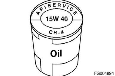
Some state and federal agencies have determined that used engine oil can be carcinogenic and can cause reproductive toxicity. Avoid inhalation of vapors, ingestion, and prolonged contact with used engine oil. If not reused, dispose of in accordance with local environmental regulations. Figure 136
WARNING!
To reduce the possibility of personal injury, avoid direct contact of hot oil with your skin.
Install the dipstick in the dipstick tube housing. Use clean 15W-40 oil to fill the oil pan to the specified LOW oil level. Refer to Lubricating Oil System Specifications in Procedure 018-017 of this manual for the correct engine oil capacity.
CAUTION!
Use care when marking the dipstick. The dipstick will break if the scribe mark is too deep.
Remove the dipstick and scribe a mark across the stick at the oil level. Label the mark with an L to indicate the "LOW" oil level. NOTE: If a new blank dipstick is being used, cut the dipstick off approximately 38mm [1.5 in] below the LOW oil level mark.
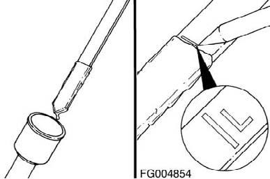
Figure 137
QSL9CumminsEng QSL9 Cummins Engine Page 99
Wipe off the dipstick and install it in the dipstick tube housing. Fill the oil pan to the specified HIGH oil level. Refer to Lubricating Oil System Specifications in Procedure 018- 017 of this manual for the correct engine oil capacity.
Remove the dipstick and scribe a mark across the stick at the oil level. Label the mark with an H to indicate the HIGH oil level.
CAUTION!
Use care when marking the dipstick. The dipstick will break if the scribe mark is too deep. Figure 138
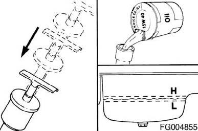
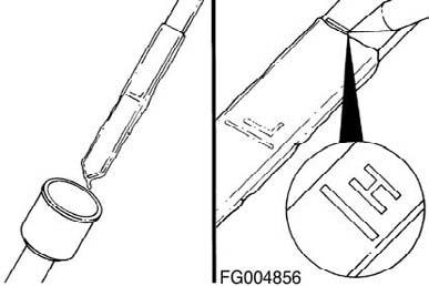
Figure 139
Drive Belt, Cooling Fan
Remove
Lift the tensioner to remove the drive belt. NOTE: The belt tensioner is spring-loaded and must be pivoted away from the drive belt. Pivoting in the wrong direction can result in damage to the belt tensioner.
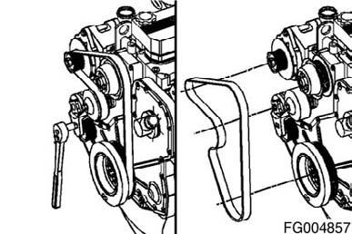
Figure 140
QSL9 Cummins Engine Page 100 QSL9CumminsEng
Install
Lift and hold the belt tensioner. Install the drive belt and release the tensioner. NOTE: The belt tensioner is spring-loaded and must be pivoted away from the drive belt. Pivoting in the wrong direction can result in damage to the belt tensioner. Service Tip: If difficulty is experienced installing the drive belt (i.e., the belt seems too short), position the belt over the grooved pulleys first then while holding the tensioner up, slide the belt over the water pump pulley.
Figure 141
Belt Tensioner, Automatic (Water Pump)
Initial Check
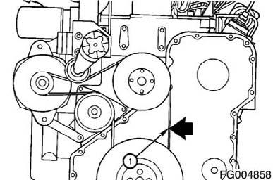
Check the belt deflection at the longest span of the belt. The deflection must be checked at the center (1) of the span. The maximum deflection allowed in the belt is 9.5 to 12.7mm [3/ 8 to 1/2-in].
Use the Cummins belt tensioner gauge, Part Number ST- 1293, to measure the tension in the drive belt. This needs to be in the range of 360 to 480 N [80 to 100 ft-lb]. Check the tensioner arm, pulley, and stops for cracks. If any cracks are noticed, the tensioner must be replaced.
With the belt on, verify that neither tensioner arm stops are in contact with the spring casing stop. If either stop is touching, the drive belt must be replaced. After replacing the belt, if the tensioner arm stops are still in contact with the spring casing stop, replace the tensioner.
Figure 142
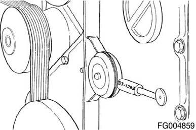
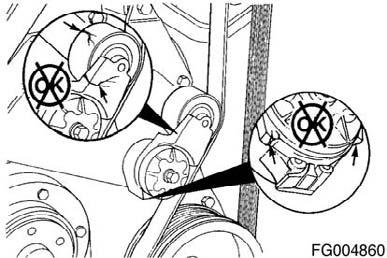
Figure 143
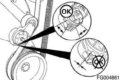
Figure 144
QSL9CumminsEng QSL9 Cummins Engine Page 101
Remove
Lift the tensioner to relieve tension on the belt and remove the belt.
Install
Lift and hold the belt tensioner. Install the drive belt and release the tensioner. NOTE: If difficulty is experienced installing the drive belt (i.e., the belt seems too short), position the belt over the grooved pulleys first and then, while holding the tensioner up, slide the belt over the water pump pulley.
Figure 145
Alternator
Remove
WARNING!
Batteries can emit explosive gases. To reduce the possibility of personal injury, always ventilate the compartment before servicing the batteries. To reduce the possibility of arcing, remove the negative (-) battery cable first and attach the negative (-) battery cable last.
Remove and tag all wires and complete the following steps: • Disconnect the ground cable from the battery terminal. Remove the alternator link cap screw.
Figure 146
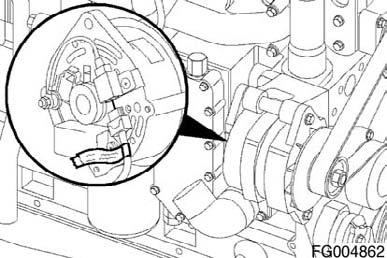
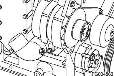
Figure 147
QSL9 Cummins Engine Page 102 QSL9CumminsEng
Install
Install the alternator and alternator cap screws in the reverse order of removal. Torque Value: 43 Nm [32 ft-lb]
Install the alternator link cap screw. Torque Value: 24 Nm [18 ft-lb]
Connect all wires to the alternator. Connect the battery ground cable.
Figure 148
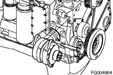
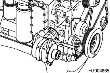
Figure 149
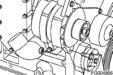
Figure 150

Figure 151
QSL9CumminsEng QSL9 Cummins Engine Page 103
Pressure Test
Mercury Manometer, Part Number ST-1111-3 Preferred Method Measure the charge air cooler system pressure drop with a mercury manometer.
Install one end of a mercury manometer, Part Number ST- 11113, in the 1/8-inch fitting in the turbocharger compressor outlet elbow. Install the other end of the mercury manometer in the intake manifold.
Operate the engine at rated rpm and load. Record the readings on the manometer. If the differential pressure is greater than 152mm Hg [6 in Hg], check the charge air cooler and associated piping for plugging, restrictions, or damage. Clean or replace, if necessary.
Pressure Gauge, Part Number ST-1273 Optional Method Obtain two pressure gauges, Part Number ST-1273. Check both gauges on the same pressure source at 206 kPa [30 psi] to maintain consistency. Install one pressure gauge in the 1/8-inch fitting in the turbocharger compressor outlet elbow. Install the other pressure gauge in the intake manifold.
Figure 152
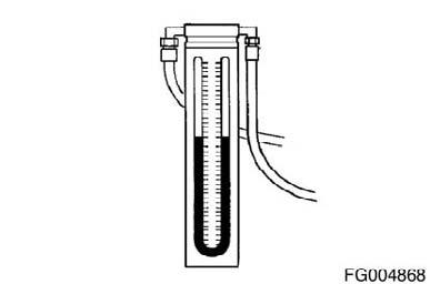
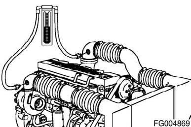
Figure 153
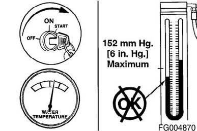
Figure 154
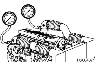
Figure 155
QSL9 Cummins Engine Page 104 QSL9CumminsEng
Operate the engine at rated rpm and load. Record the readings on the two gauges. If the differential pressure is greater than 152mm Hg [6 in Hg], check the charge air cooler and associated piping for plugging, restrictions, or damage. Clean or replace, if necessary.
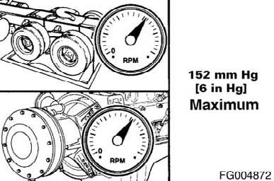
Figure 156
Leak Test
WARNING!
To prevent possible injury if either plug blows off during the test, secure safety chains on the test plugs to any convenient cap screw on the radiator assembly. This test must be performed with securely fastened safety chains.
To check the charge air cooler for cracked tubes or header, remove the inlet and outlet hoses from the cooler. The charge air cooler does not have to be removed from the chassis. Install a plug or cap over the outlet side of the cooler. Install a pressure gauge and a regulated shop air supply line with a shutoff valve to the inlet side of the cooler. Apply air pressure to the cooler until the pressure gauge reads a steady 207 kPa [30 psi] of air pressure. Shutoff the air flow to the cooler, and start a stopwatch at the same time. Record the leakage at 15 seconds. If the pressure drop is 48 kPa [7 psi] or less in 15 seconds, the cooler is operational. If the pressure drop is greater than 48 kPa [7 psi] in 15 seconds, check all connections again.
Figure 157
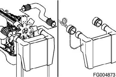
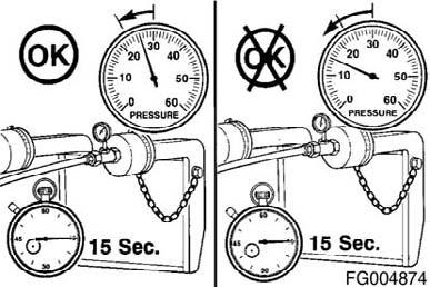
Figure 158
QSL9CumminsEng QSL9 Cummins Engine Page 105
Determine if the pressure drop is caused by a leak in the charge air cooler or by a leaky connection. Use a spray bottle filled with soapy water applied to all hose connections, and watch for bubbles to appear at the location of the leak. If the pressure drop is caused by a leaky connection, repair the connection, and repeat the test. If the leak is within the charge air cooler, repeat the test to verify the accuracy of the pressure drop measurement. Similar pressure drop readings must be obtained at least three consecutive tests before the reading can be considered accurate. NOTE: If a charge air cooler leaks more than 48 kPa [7 psi] in 15 seconds, it will appear as a major leak in a leak tank. If the pressure drop is greater than 48 kPa [7 psi] in 15 seconds, the charge air cooler must be replaced. Refer to the equipment manufacturer's service manual for replacement instructions. NOTE: Charge air coolers are not designed to be 100percent leak-free. If the pressure drop is less than 48 kPa [7 psi] in 15 seconds, then the charge air cooler does not need to be replaced.
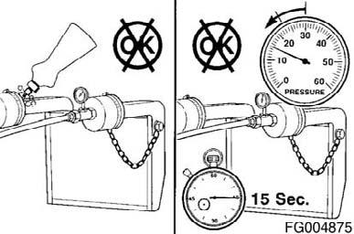
Figure 159
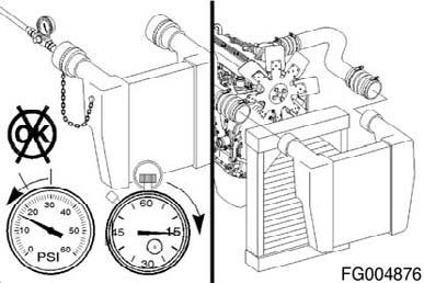
Figure 160
Temperature Differential Test
Inspect the charge air cooler fins for obstructions to air flow. Remove obstructions such as a winterfront or debris. Manually lock shutters in the OPEN position, if equipped. Lock the fan drive in the ON mode to prevent erratic test results. This can be done by installing a jumper wire across the temperature switch.
Install fluke digital thermometer, Part Number 3822666, into the intake manifold at the 1/8-inch NPT tap near the air horn connection with the intake manifold.
Another alternative is to use the monitor mode on the INSITETM electronic service tool. Install another thermocouple at the air cleaner inlet to measure ambient air temperature.
Figure 161
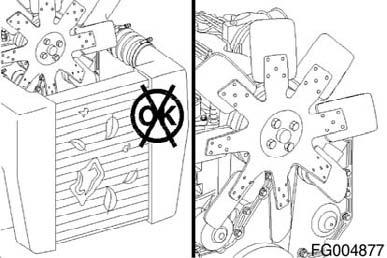

Figure 162
QSL9 Cummins Engine Page 106 QSL9CumminsEng
Perform a road test with the engine at peak power and a vehicle speed of 40 km/h [25 MPH] or greater. Record the intake manifold temperature and the ambient air temperature. Calculate the differential temperature: • Intake Manifold Temperature minus Ambient Air Temperature equals Differential Temperature • Maximum Differential Temperature equals 35°C [63°F].
If the temperature differential is greater than the specifications, check the charge air cooler for dirt and debris on the fins and clean as necessary. If the problem still exists, check the charge air cooler for debris in the fins or between the charge air cooler and radiator. Confirm full fan engagement.
Figure 163
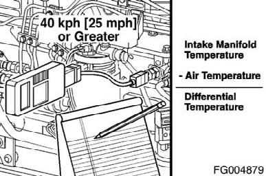
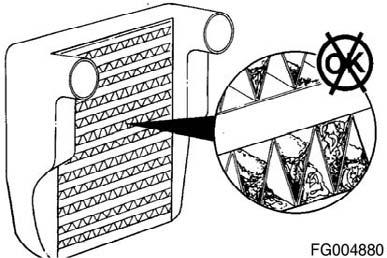
Figure 164
Starting Motor
Preparatory Steps
WARNING!
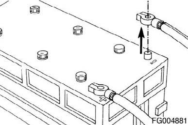
Batteries can emit explosive gases. To reduce the possibility of personal injury, always ventilate the compartment before servicing the batteries. To reduce the possibility of arcing, remove the negative (-) battery cable first and attach the negative (-) battery cable last.
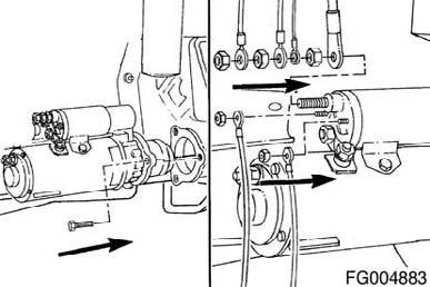
Disconnect the ground cable from the battery terminal. Remove and tag all wires.
Figure 165
QSL9CumminsEng QSL9 Cummins Engine Page 107
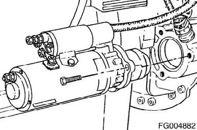
Remove
Remove the three cap screws and the starting motor. If equipped with a starting motor spacer, remove the spacer and clean all surfaces between the starting motor, starting motor spacer, and flywheel housing with a wire brush.
Install
Install the starting motor in the reverse order of removal. Torque Value: 43 Nm [32 ft-lb] Connect all electrical connections to the starting motor.
Figure 166