3 minute read
System Diagrams

System Diagrams - Overview
General Information
The following drawings show the flow through the engine systems. Although parts can change between different applications and installations, the flow remains the same. The systems shown are: • Fuel System • Lubricating Oil System • Coolant System • Intake Air System • Exhaust System • Compressed Air System Knowledge of the engine systems can help you in troubleshooting, service, and general maintenance of your engine.
QSL9CumminsEng QSL9 Cummins Engine Page 109
Figure 168 Cummins Common Rail Fuel System
Reference Number Description
1 Fuel From Supply Tank 2 Fuel Filter And Water Separator 3 Oem Fuel Supply Connection 4 Fuel Supply To Ecm Mounted Fuel Lift Pump 5 Ecm Cooling Plate 6 Ecm Mounted Fuel Lift Pump 7 Fuel Outlet From Ecm Mounted Fuel Lift Pump 8 Fuel Gear Pump 9 Fuel From Gear Pump To Fuel Filter 10 Primary Fuel Filter 11 Fuel Inlet To Fuel Pump Actuator 12 High-pressure Fuel Pump 13 Fuel Outlet From High-pressure Pump 14 High-pressure Pump Drain Flow Connection 15 Fuel Rail 16 High-pressure Injector Supply Lines 17 High-pressure Fuel Connector 18 Fuel Injector 19 Fuel Pressure Relief Valve 20 Fuel Injector Drain Flow Line 21 Fuel Return To Supply Tanks
Reference Number Description
QSL9 Cummins Engine Page 110 QSL9CumminsEng

Figure 169 Cummins Common Rail Fuel System
QSL9CumminsEng QSL9 Cummins Engine Page 111
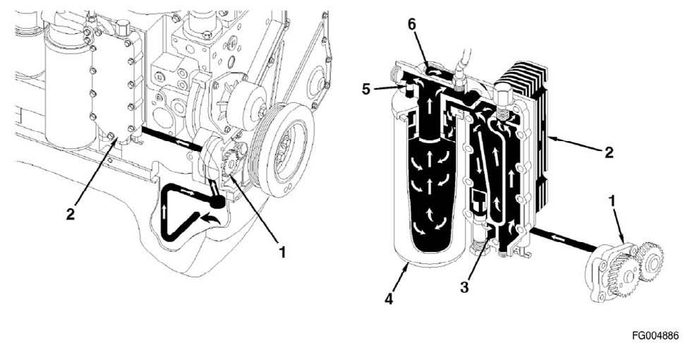
Figure 170 Lubricating Oil Cooler Flow
Reference Number Description
1 Gerotor Lubricating Oil Pump 2 Lubricating Oil Cooler 3 To Lubricating Oil Pan 4 Full Flow Lubricating Oil Filter 5 Filter Bypass Valve 6 From Lubricating Oil Filter
Reference Number Description
QSL9 Cummins Engine Page 112 QSL9CumminsEng
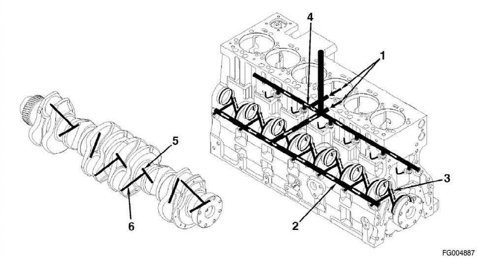
Figure 171 Lubrication for Power Components (All ISL engines and QSL engines with CM850 Electronic Control Module)
Reference Number Description
1 From Lubricating Oil Cooler 2 Main Lubricating Oil Rifle 3 To Camshaft 4 To Piston Cooling Nozzle 5 From Main Lubricating Oil Rifle 6 To Connecting Rod Bearing
Reference Number Description
QSL9CumminsEng QSL9 Cummins Engine Page 113
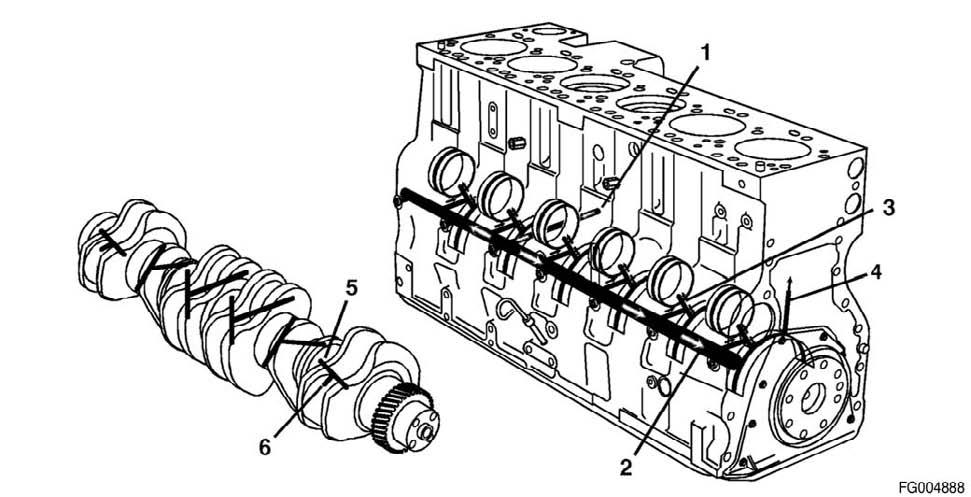
Figure 172 Lubrication for Turbocharger
Reference Number Description
1 Lubricating Oil Supply From Filter 2 Turbocharger Lubricating Oil Supply 3 Turbocharger Lubricating Oil Drain
Reference Number Description
QSL9 Cummins Engine Page 114 QSL9CumminsEng
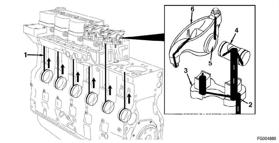
Figure 173 Lubrication for the Overhead
Reference Number Description
1 From Cam Bushings 2 Transfer Slot 3 Rocker Lever Support 4 Rocker Lever Shaft 5 Rocker Lever Bore 6 Rocker Lever
Reference Number Description
QSL9CumminsEng QSL9 Cummins Engine Page 115
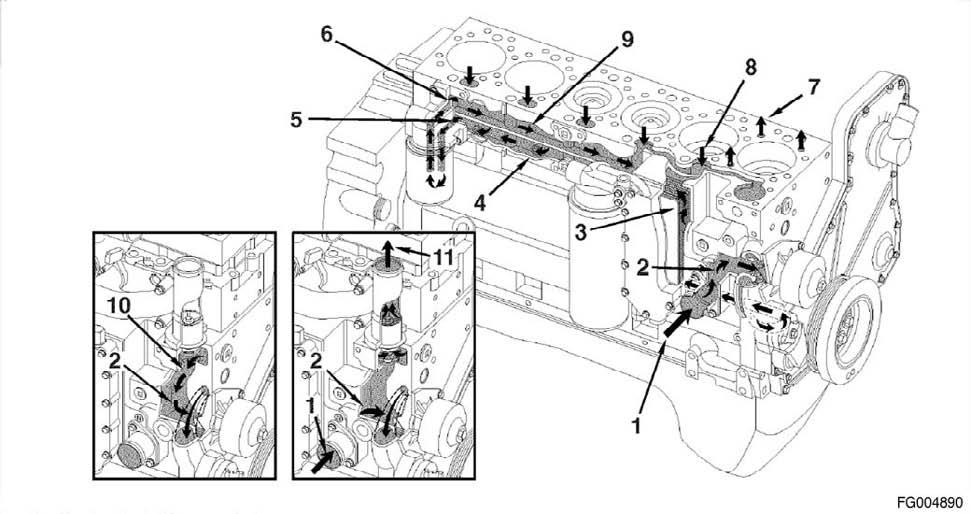
Figure 174
Reference Number Description
1 Coolant Inlet From Radiator 2 Water Pump Suction 3 Coolant Flow Through Lubricating Oil Cooler 4 Rocker Lever Shaft 5 Coolant Filter Inlet (Optional) 6 Coolant Filter Outlet (Optional) 7 Coolant Supply To Cylinder Head 8 Coolant Return From Cylinder Head 9 Block Upper Water Manifold 10 Thermostat Bypass 11 Coolant Return To Radiator
Reference Number Description
QSL9 Cummins Engine Page 116 QSL9CumminsEng

Figure 175
Reference Number Description
1 Turbocharger coolant supply
Reference Number Description
2 Turbocharger coolant drain
QSL9CumminsEng QSL9 Cummins Engine Page 117
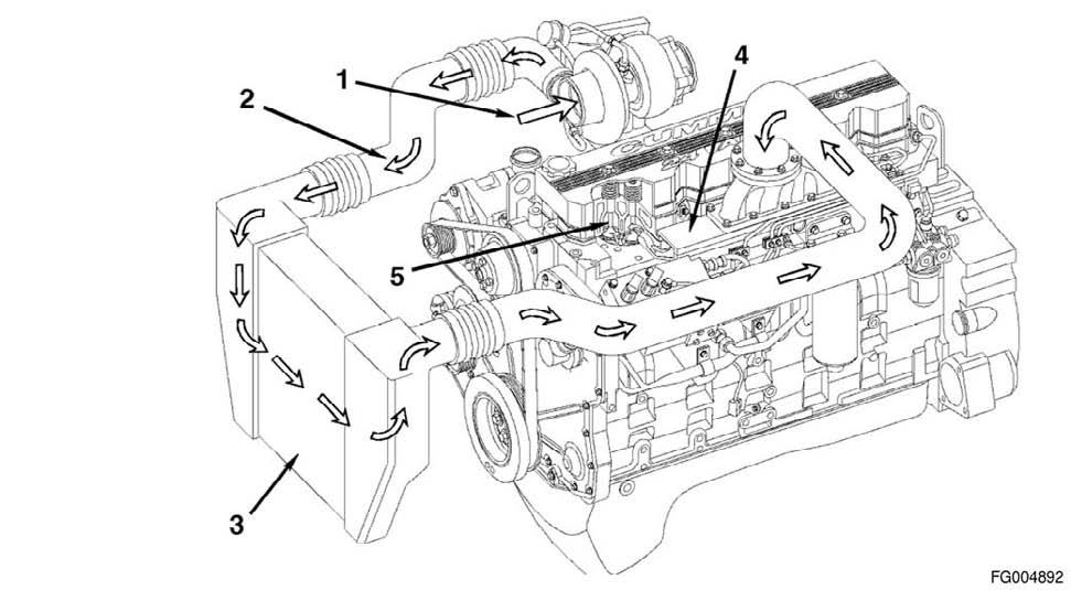
Figure 176
Reference Number Description
1 Intake Air Inlet to Turbocharger 2 Turbocharger Air to Charge Air Cooler 3 Charge Air Cooler 4 Intake Manifold (integral part of cylinder head) 5 Intake Valve
Reference Number Description
QSL9 Cummins Engine Page 118 QSL9CumminsEng
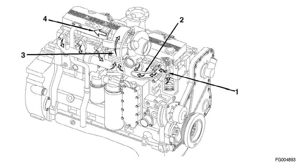
Figure 177
Reference Number Description
1 Exhaust valve 2 Exhaust manifold (pulse type) 3 Dual-entry turbocharger 4 Turbocharger exhaust outlet