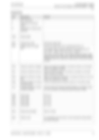
1 Overall hydraulic system Hydraulic Circuit Diagram QUANTUM 6800 P - 4700 P 26927 1 Overall hydraulic Hydraulic Circuit Diagram systemQUANTUM 6800 P - 4700 P
Designations Item
Designation
Remark
I
Main valve block
-
II
Valve block for solenoid valves
-
III
Valve block for steering axle (optional)
-
-
-
-
1002
Pressure filter
-
-
-
-
2037
Scraper floor motor
Drives the scraper floor.
2073
2-stage motor for scraper floor
Drives the scraper floor. Not in QUANTUM 4700 P / S. The 2-stage motor contains 2 rotor sets with a displacement of 95 cm3/rev. = stage 1 and 195 cm3/rev. = stage 2. Flow rate to rotor set stage 1 (low displacement) generates a high speed but low torque. Flow rate to rotor set stage 2 (large displacement) generates a low speed but a high torque = Start of the unload process.
-
-
-
3018
Hydraulic cylinder for tailgate
Opens and closes the tailgate. As pressure builds up in the piston space, the tailgate is opened.
3031
Hydraulic cylinder for pick-up
Lifts and lowers the pick-up. As pressure increases in the piston space, the pick-up is lifted.
3042
Hydraulic cylinder for cutting floor
Opens and closes the cutting floor. As pressure builds up in the rod space, the cutting floor is closed.
3084
Hydraulic cylinder for locking the steering axle
Locks the steering axle if pressure builds up in the piston space.
3191
Hydraulic cylinder for hydraulic high-lift drawbar
Lifts and lowers the hydraulic high-lift drawbar. As pressure builds up in the rod space, the hydraulic high-lift drawbar is lifted.
-
-
-
4006
Orifice plate
Ø 0.8 mm
4007
Orifice plate
Ø 1.0 mm
4013
Orifice plate
Ø 2.2 mm
4019
Orifice plate
Ø 7.5 mm
-
-
-
5015
Pressure accumulator
750 cm3, 40 bar.
-
-
-
6034
System screw
In LS operation, turn the screw in until it reaches the stop position the valve is blocked.
-
-
-
000 295 554 0 - QUANTUM 6800 - 4700 S / P - 02/08
13
