1 minute read
Removing and storing the front attachment...........................7


without additional equipment “Hydraulic paddle adjustment”
2
3
without additional equipment “Hydraulic paddle adjustment”
4 5 DANGER!
Danger of crushing at pinch points on pretensioned components. Serious injuries. –Never reach in between pretensioned components. –Use suitable aids to secure pretensioned components or relieve them. –Follow the instructions.
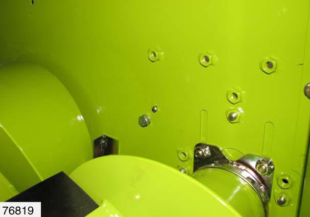
The help of another person is required here. –Open left side panelling –see Side panelling, page9.50. –Unscrew nut(2). –Loosen bolt(3) slightly. (Fig.31)
31
–Grip clamping bracket(5) by the square tube using a suitable tool (e.g. side levelling width across flats55). –Remove bolt(4). (Fig.32)
32
without additional equipment “Hydraulic paddle adjustment”
5
without additional equipment “Hydraulic paddle adjustment” 33
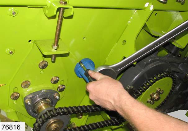
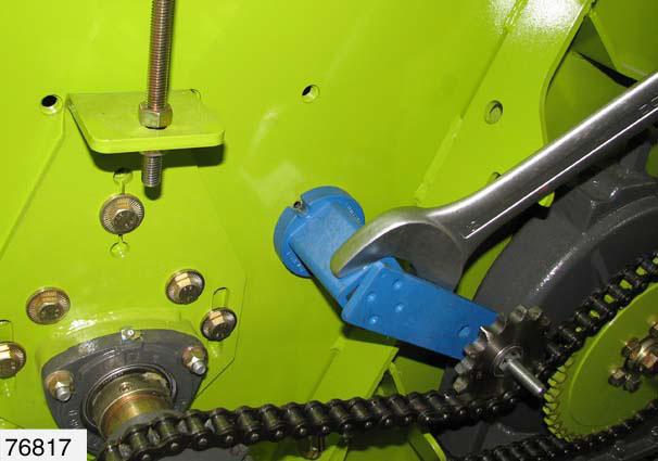
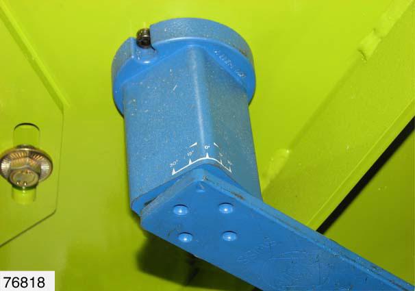
–Using a suitable tool (for example side levelling width across flats55), tension the clamping bracket at the clamping bracket square tube(5). –Turn square tube clockwise until the mark(M) is between 5° and 15°.
–Relieve clamping bracket: –Turn square tube anticlockwise. (Fig.33,34)
M
without additional equipment “Hydraulic paddle adjustment”
4
without additional equipment “Hydraulic paddle adjustment”
2
6
B
76925
4
34
–Insert bolt(4) through the next adequately sized drilled hole(B). –Secure bolt(4) with contact washer(6) and nut(2). –Remove tool. (Fig.35,36)
35
36
without additional equipment “Hydraulic paddle adjustment”
7
M
without additional equipment “Hydraulic paddle adjustment”
2
6
B
4
76925
without additional equipment “Hydraulic paddle adjustment”
2
3
37
–Check adjustment at the display(7) on the clamping bracket. Possible positions for the mark(M):
–Correct as necessary. (Fig.37,38)
Mark Chain tension
between 5°/ 15° OK
less than 5° too low Displace bolt(3) by one drilled hole(+) or replace or shorten chain
greater than 15° too high Displace bolt(3) by one drilled hole(-) or replace or lengthen chain
Remedy
38
–Tighten nut(2). –Tighten bolt(3). (Fig.39)
39
–Close left side panelling –see Side panelling, page9.50.