8 minute read
Power unit ................................................................ 5


BI632977
Power unit
The power unit (Fig. 60) has been assembled as a unit and can be removed as a unit or as individual components. As soon as any component of the power unit is worn or damaged, the component must be replaced.
The power unit consists of the following main components:
■ gear pump
■ hydrostatic pump
■ pump coupling
■ motor (200 hp)
■ reducer/motor coupling
■ reducer
■ torque limiter
■ connecting tube
Fig. 60: Power unit main components
Coupling Motor (200 HP) Coupling Taperlock bushing
Torque limiter Reducer
Hydrostatic pump
Gear pump Connecting tube Connecting tube Companion flange
BI632977
How to remove the power unit
To remove the power unit as a complete assembly proceed as follows (Fig. 61).
Remove power unit covers from the machine.
Disconnect and tag all electrical wiring to the drive motor.
WARNING! Before performing maintenance on the machine, the circuit breaker must be in the “OFF” position and the power should be disconnected at the main power source. Electrical shock and accidental machine movement can cause serious injuries or even death to you or the maintenance person.
Disconnect, cap and tag all hydraulic hoses to the hydraulic pumps.
Remove the twelve (12) mounting bolts, nuts and lockwashers from the breaker shaft flange and stub shaft.
Remove the power unit reaction pin.
Attach an appropriate lifting device to the complete unit and slowly lift the unit from the machine.
WARNING! You could be seriously injured or even killed by falling loads. Observe the safe working load limits of lifting or blocking devices and keep a safe distance from suspended loads.
How to install the power unit
To install the power unit as a complete assembly proceed as follows (Fig. 61).
Attach an appropriate lifting device to the complete unit and slowly lift the unit onto the machine and align stub shaft with breaker shaft flange.
WARNING! You could be seriously injured or even killed by falling loads. Observe the safe working load limits of lifting or blocking devices and keep a safe distance from suspended loads.
Install the twelve (12) bolts, lockwashers, and nuts previously removed from the stub shaft and breaker shaft flange. Torque bolts to 350 ft-lb incrementally and evenly in a crossing pattern.
Install the power unit reaction pin and secure with the two (2) cotter pins.
Connect all hydraulic hoses to the hydraulic pumps.
Connect all electrical wiring to the drive motor.
Install power unit covers.
BI632977
Fig. 61: Power unit removal and installation
Breaker shaft flange
Flange and shaft connecting bolts Torque to 350 ft– lbs
Stub shaft
Pivot mounting lug
Power unit reaction pin Power unit
Top set of holes of pivot mounting plate Pivot mounting lug will always be this dimension (6.81”) from top of frame side plate.
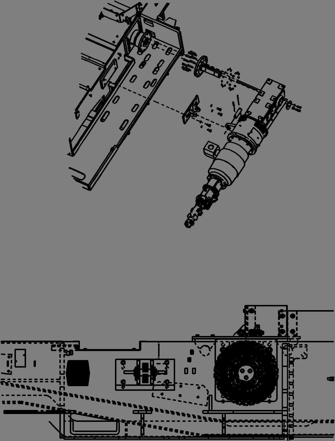
Bottom set of holes of pivot mounting plate Use the bottom set of holes on the pivot mounting plate if the breaker shaft assembly is installed using these side plate holes.
Use the bottom set of holes on the pivot mounting plate if the breaker shaft assembly is installed using these side plate holes.
BI632977
How to disassemble the breaker power unit
To disassemble the power unit proceed as follows (Fig. 63):
Remove complete unit from machine. (See How to remove the drive unit in this chapter)
Remove the four (4) bolts and lockwashers from gear pump (item 24) and remove pump.
Open access cover on connecting tube (item 18) and loosen the two (2) bolts on the pump end and set screw on the motor end of the coupling (item 17).
Remove the four (4) bolts and lockwashers from hydrostatic pump (item 21). With the aid of a lifting device, slowly pull pump from coupling (item 17) and connecting tube (item 18).
WARNING! You could be seriously injured or even killed by falling loads. Observe the safe working load limits of lifting or blocking devices and keep a safe distance from suspended loads.
Remove the eight (8) bolts and lockwashers from connecting tube (item 18) and remove connecting tube from motor (item 13).
Remove coupling (item 17) and key from motor shaft.
Remove access cover (item 26) on connecting tube (item 12) and loosen the four (4) set screws on the flexible coupling (item 9).
Connect a lifting device to motor to aid in holding the weight of the motor.
Remove the eight (8) bolts and lockwashers from connecting tube (item 12) and slowily pull motor from connecting tube and flexible coupling (item 9).
Remove the four (4) expanded matal guards (item 25) from connecting tube (item 12).
Remove the twelve (12) bolts and lockwashers from connecting tube (item 12) and remove connecting tube from reducer (item 1).
Remove the eight (8) bolts and lockwashers from flexible coupling (item 9) and remove flexible coupling.
Remove the twelve (12) bolts and lockwashers from companion flange (item 3) and remove remove torque limiter (item 6).
Remove the three (3) bolts that secures the taper lock (item 2) to the reducer shaft.
Insert two (2) of the bolts removed from the taper lock into the jack screw threaded holes located in the end of the taper lock (Fig. 62).
Tighten both bolts equally until the taper lock is free from reducer shaft.
Remove companion flange (item 3) and taper lock bushing (item 2) from reducer shaft.
Visually inspect all components for wear or damage and replace if necessary.
Fig. 62: Taper lock removal and installation
Jack screw holes (2) for bushing removal
Bolt holes (3) for bushing installation
BI632977
How to assemble the power unit
To assemble the power unit proceed as follows (Fig. 63):
Slide reducer companion flange (item 3) onto reducer shaft.
Slide taper lock (item 2) and shaft key onto reducer shaft. Locate reducer companion flange (item 3) and taper lock (item 2) so they are flush with the end of the reducer shaft. Secure taper lock with the three (3) bolts supplied with taper lock. Torque bolts to 105 ftlb.
Connect torque limiter (item 6) to companion flange (item 3) and secure with the twelve (12) bolts and lockwashers. Torque bolts to 65 ft-lb.
Connect flexible coupling (item 9) to torque limiter (item 6) and secure with the eight (8) bolts and lockwashers. Torque bolts to 90 ft-lb.
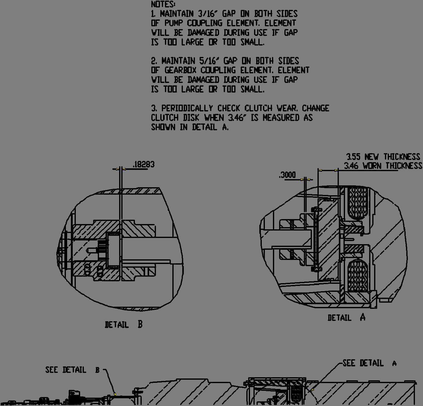
NOTICE! A 5/16” gap must be maintained on both sides of flexible coupling (item 9) or coupling will be damaged during use if gap is too large or too small.
Connect connecting tube (item 12) to reducer (item 1) and secure with the twelve (12) bolts and lockwashers. Torque bolts to 380 ftlb.
With the aid of a lifting device, slowly lift motor (item 13). Align motor shaft key and slide motor shaft into flexible coupling (item 9).
WARNING! You could be seriously injured or even killed by falling loads. Observe the safe working load limits of lifting or blocking devices and keep a safe distance from suspended loads.
Insert key into slot of motor shaft and slide motor coupling half (item 17) onto motor shaft until shaft and coupling face are flush.
Tighten set screw in motor half of coupling.
Insert coupling element into motor half of coupling.
Align the 8 holes of connecting tube (item 18) with motor (item 13) and secure with the eight (8) bolts and lockwashers. Torque bolts to 2400 ft-lb.
Apply never seez to pump half of coupling (item 17) and slide onto hydrostatic pump shaft (item 21) until a 3/16” shaft end gap is acquired. Tighten the two (2) coupling half bolts.
NOTICE! A 3/16” gap must be maintained on both sides of pump coupling (item 17) or coupling will be damaged during use if gap is too large or too small.
With the aid of a lifting device, slowly lift hydrostatic pump (item 21) and carefully align pump half and motor half of coupling. Secure pump to connecting tube with four (4) bolts and lockwashers.
Torque bolts to 380 ft-lb. Coupling spacing should be 3/16” after pump mounting bolts are tightened.
Align mounting holes and shaft of gear pump (item 24) with hydrostatic pump (item 21) and secure with four (4) bolts and lockwashers. Torque bolts to 90 ft-lb.
Install completed power unit onto machine. (See How to install the power unit in this chapter)
Fill hydrostatic pump thru case drain port with system oil before running pump.
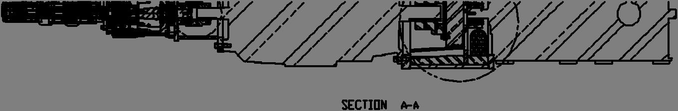
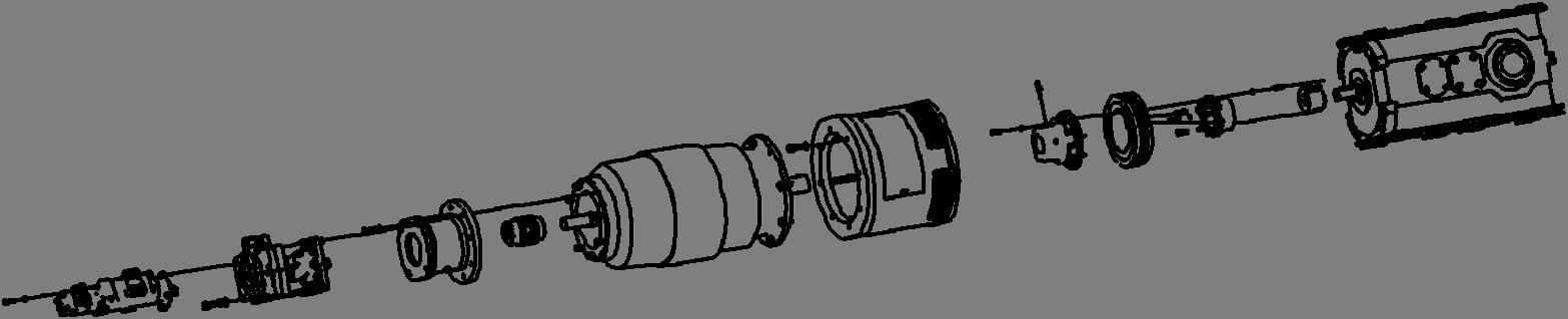
Fig. 63: Power unit disassembly and assembly
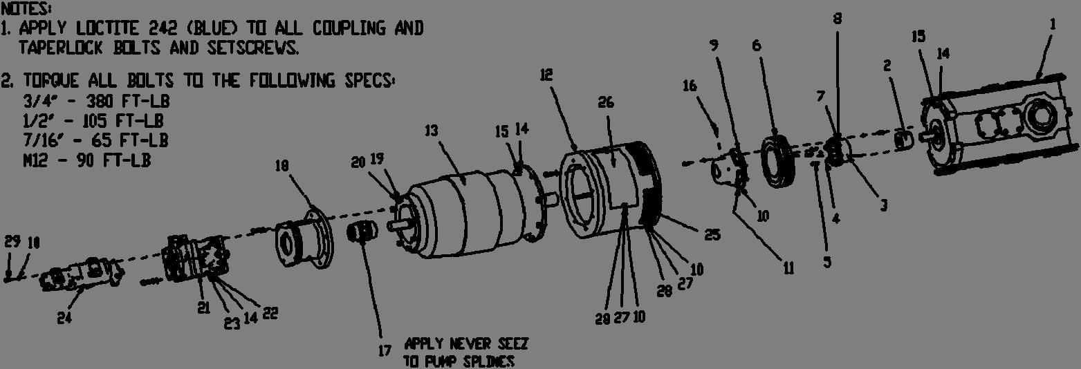
1. reducer 2. taper lock bushing 3. companion flange 4. washer (lock) 5. bolt 1/2” 6. torque converter 7. washer (lock) 8. bolt 7/16” 9. flexible coupling 10. washer (lock) 11. bolt M12 12. connecting tube 13. motor 14. washer (lock) 15. bolt 3/4” 16. Set screw 1/2” 17. coupling 18. connecting tube 19. washer (lock) 20. bolt 5/8” 21. hydrostatic pump 22. washer (flat) 23. bolt 3/4” 24. tandem gear pump 25. metal guard 26. cover 27. washer (flat) 28. bolt 1’2” 29. bolt M12
BI632977
Fig. 63: Power unit disassembly and assembly (continued)