11 minute read
Breaker assembly ..................................................... 5


BI632977
Breaker assembly
The breaker assembly (Fig. 65) is assembled as a complete unit and should be removed as a unit for repairs except for the replacement of the drive flange, bits and magnetic cutoff assembly. As soon as any component of the breaker assembly is worn or damaged, the component or complete assembly must be replaced.
The breaker assembly consists of the following main components:
■ breaker shaft ■ drive flange ■ bearing housing (2) ■ bearing (2) ■ bits (30) ■ bearing retainer (2) ■ magnetic cutoff assembly ■ lockwasher (3) ■ breaker side plate (2) ■ end cap ■ dust cover
Fig. 65: Breaker assembly main components
Bearing retainer
Pick (30) Seal housing
Breaker shaft
Bearing backing ring
Bearing Bearing Flange
End cap
Side plate
Bearing housing
Side plate
Seal housing Bearing backing ring
Under speed sensor Bearing housing Bearing retainer
BI632977
How to remove the breaker assembly
To remove the breaker assembly from the machine proceed as follows (Fig. 66):
Remove covers and guards as required to gain access to the breaker assembly.
Remove the twelve (12) bolts, lockwashers, nuts and wire tie from the breaker shaft connecting flange.
Disconnect, tag and cap the bearing central lubrication hoses.
Attach an appropriate lifting device around the breaker shaft assembly and apply just enough lift to remove the tweenty (20) bolts, nuts, flatwashers and lockwashers (10 per side) that secure the breaker assembly to the frame.
WARNING! You could be seriously injured or even killed by falling loads. Observe the safe working load limits of lifting or blocking devices and keep a safe distance from suspended loads.
With the aid of the lifting device, slowly lift the complete assembly out of the frame.
How to install the breaker assembly
To install the breaker assembly into the machine proceed as follows (Fig. 66):
With the aid of the lifting device, slowly lift the breaker assembly into the frame and align mounting holes.
Secure the breaker with the tweenty (20) bolts, nuts, flatwashers and lockwashers (10 per side) and securely tighten. Apply never seez to bolt threads. Secure bolts with wire tie after tightening.
Connect breaker flange to the reducer stub shaft with thetwelve (12) bolts, lockwashers and nuts previously removed. Torque bolts to 350 ft-lb incrementally and evenly in a crossing pattern.
Connect the bearing central lubrication hoses.
Install covers and guards.
BI632977
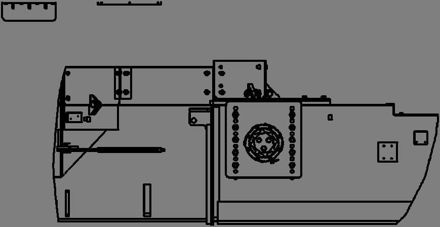
Fig. 66: Breaker assembly removal and installation
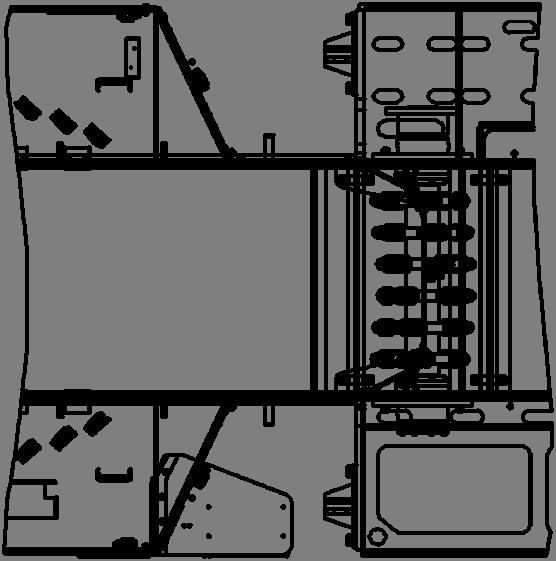
Breaker shaft assembly
Breaker shaft connecting flange
Breaker shaft mounting bolts
BI632977
How to disassemble the breaker assembly (drive side)
To disassemble the breaker assembly (drive side) proceed as follows (Fig. 67 and 68):
Remove the breaker assembly from the machine. (See How to remove the breaker assembly in this chapter).
Remove the three (3) bolts (item 26) from shaft and remove end cap (item 23).
Remove the breaker shaft flange (item 21) from shaft.
Remove the eight (8) bolts and lockwashers (items 18 and 20) and remove seal housing (item 14).
Remove o-ring (item 11), retaining ring (item 16) and seal (item 15) from seal housing (item 14).
Remove side plate (item 13) from shaft.
Remove the eight (8) bolts and lockwashers (items 9 and 10) and remove bearing housing (item 8).
IMPORTANT! Use tool P/N 356549 to aid in disassembly of breaker shaft.
Remove sealing ring (item 7) from shaft.
Remove bearing (item 6) from shaft.
Remove 0-ring (item 5) from shaft.
Remove bearing retainer ring (item 4) from shaft.
Remove seal (item 3) from shaft.
Remove bearing backing (item 2) from shaft.
Visually inspect all components for wear or damage and replace as necessary.
BI632977
How to disassemble the breaker assembly (underspeed sensor side)
To disassemble the breaker assembly (drive side) proceed as follows (Fig. 67 and 68):
Remove the breaker assembly from the machine. (See How to remove the breaker assembly in this chapter).
Remove the three (3) bolts (item 25) and lockwashers (item 24) from shaft and remove end cap (item 22).
Remove the eight (8) bolts (item 19) and lockwashers (item 18) and remove underspeed sensor mount (item 17).
Remove seal housing (item 14).
Remove o-ring (item 11), retaining ring (item 16) and seal (item 15) from seal housing (item 14).
Remove side plate (item 13) from shaft.
Remove the eight (8) bolts and lockwashers (items 9 and 10) and remove bearing housing (item 8).
IMPORTANT! Use tool P/N 356549 to aid in disassembly of breaker shaft.
Remove sealing ring (item 7) from shaft.
Remove bearing (item 6) from shaft.
Remove 0-ring (item 5) from shaft.
Remove bearing retainer ring (item 4) from shaft.
Remove seal (item 3) from shaft.
Remove bearing backing (item 2) from shaft.
Visually inspect all components for wear or damage and replace as necessary.
BI632977
How to assemble the breaker assembly (drive side)
To assemble the breaker assembly proceed as follows (Fig. 67 and 68):
Thoroughly clean all components with dry and lint free cloth prior to assembly.
IMPORTANT! Apply LOCTITE 518 gasket eliminator before installing bearing backing ring (item 2).
Install bearing backing ring (item 2).
IMPORTANT! Seal bores of bearing backing ring (item 2) and bearing retainer ring (item 4) must be completely free of grease and oil before installing seal (item 3).
IMPORTANT! Clean mating faces of metal seal rings with a lint free cloth. Apply a light coat of 30W oil to the faces only. DO NOT GET GREASE OR OIL ON THE RUBBER RINGS.
Install one half of seal (item 3) into bearing backing ring (item 2).
Install one half of seal (item 3) into bearing retaining ring (item 4).
IMPORTANT! Apply a light coat of grease to o-ring (item 5) to aid in assembly and to avoid cutting during installation. Also apply a light coat grease to bearing housing bore (item 4) to aid in installation.
Install o-ring (item 5) into bearing retaining ring (item 4).
Install bearing retainer ring (item 4) onto breaker shaft.
IMPORTANT! Use bearing installation tool (P/N 323334) to install bearing (item 6), sealing ring (item 7) and bearing backing ring (item 2). Apply 60 tons (10,000 psi) of force to seat bearing. DO NOT APPLY HEAT TO BEARING.
Install bearing (item 6) and sealing ring (item 7) onto breaker shaft.
Install bearing housing (item 8) and secure with eight (8) bolts (item 10) and lockwashers (item 9). Torque bolts to 140 ft-lb.
IMPORTANT! Ensure that 1/4” pipe plugs (item 12) installed in face of bearing housing (item 8) are flush or below face of housing.
Install pipe plugs (item 12) into bearing housing (item 8). Ensure that pipe plugs are flush or below face of housing.
BI632977
IMPORTANT! Use tool (P/N 333685) to install seal (item 15). Be careful to avoid folding lip of seal under during installation over sealing ring (item 7).
Install seal (item 15) using tool (P/N 333685) and retainer ring (item 16) into seal housing (item 14).
IMPORTANT! Apply a light coat of grease to o-ring (item 11) to aid in assembly and to avoid cutting during installation.
Install o- ring (item 11) into seal housing (item 14).
Install assembled seal housing (item 14) and secure with the eight bolts (item 20) and lockwashers (item 18). Torque bolts to 115 ft-lb.
Install side plate (item 13).
IMPORTANT! Apply never seez to splines of flange (item 21) or breaker shaft (item 1).
Apply never seez to splines of flange (item 21) and install flange on breaker shaft (item 1).
IMPORTANT! Bolt heads of (item 26) must not be above end cap (item 23).
Install end cap (item 23) and secure with three (3) bolts (item 26).
Apply Loctite 242 (blue) to bolts and torque to 400 ft-lb. Retaining wire is not necessary.
BI632977
How to assemble the breaker assembly (underspeed sensor side)
To assemble the breaker assembly proceed as follows (Fig. 67 and 68):
Thoroughly clean all components with dry and lint free cloth prior to assembly.
IMPORTANT! Apply LOCTITE 518 gasket eliminator before installing bearing backing ring (item 2).
Install bearing backing ring (item 2).
IMPORTANT! Seal bores of bearing backing ring (item 2) and bearing retainer ring (item 4) must be completely free of grease and oil before installing seal (item 3).
IMPORTANT! Clean mating faces of metal seal rings with a lint free cloth. Apply a light coat of 30W oil to the faces only. DO NOT GET GREASE OR OIL ON THE RUBBER RINGS.
Install one half of seal (item 3) into bearing backing ring (item 2).
Install one half of seal (item 3) into bearing retaining ring (item 4).
IMPORTANT! Apply a light coat of grease to o-ring (item 5) to aid in assembly and to avoid cutting during installation. Also apply a light coat grease to bearing housing bore (item 4) to aid in installation.
Install o-ring (item 5) into bearing retaining ring (item 4).
Install bearing retainer ring (item 4) onto breaker shaft.
IMPORTANT! Use bearing installation tool (P/N 323334) to install bearing (item 6), sealing ring (item 7) and bearing backing ring (item 2). Apply 60 tons (10,000 psi) of force to seat bearing. DO NOT APPLY HEAT TO BEARING.
Install bearing (item 6) and sealing ring (item 7) onto breaker shaft.
Install bearing housing (item 8) and secure with eight (8) bolts (item 10) and lockwashers (item 9). Torque bolts to 140 ft-lb.
IMPORTANT! Ensure that 1/4” pipe plugs (item 12) installed in face of bearing housing (item 8) are flush or below face of housing.
Install pipe plugs (item 12) into bearing housing (item 8). Ensure that pipe plugs are flush or below face of housing.
BI632977
Install side plate (item 13).
IMPORTANT! Use tool (P/N 333685) to install seal (item 15). Be careful to avoid folding lip of seal under during installation over sealing ring (item 7).
Install seal (item 15) using tool (P/N 333685) and retainer ring (item 16) into seal housing (item 14).
IMPORTANT! Apply a light coat of grease to o-ring (item 11) to aid in assembly and to avoid cutting during installation.
Install o- ring (item 11) into seal housing (item 14).
Install assembled seal housing (item 14), underspeed sensor mount (item 17) and secure with the eight bolts (item 19) and lockwashers (item 18). Torque bolts to 115 ft-lb.
Install end cap (item 22) and secure with three (3) bolts (item 25) and lockwashers (item 24). Torque bolts to 400 ft-lb and secure with retaining wire.
BI632977
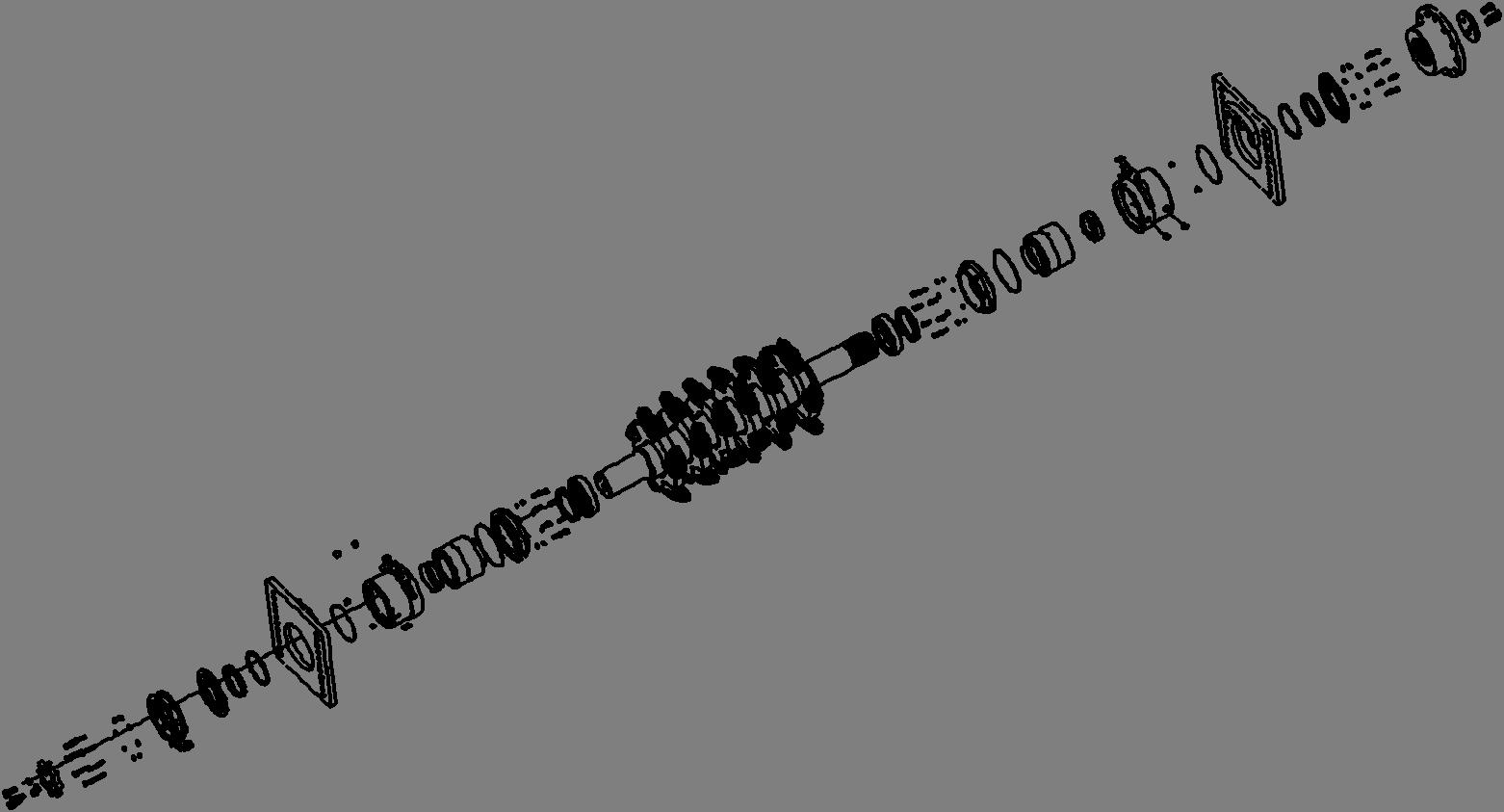
Fig. 67: Breaker shaft assembly and disassembly
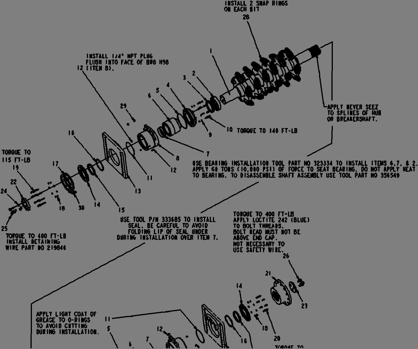
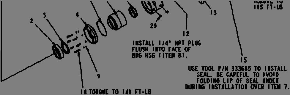
1. breaker shaft 2. bearing backing ring 3. seal 4. bearing retainer ring 5. o-ring 6. bearing 7. sealing ring 8. bearing housing 9. lock washer 10. bolt 11. o-ring 12. pipe plug 13. side plate 14. seal housing 15. seal 16. spiral retainer ring 17. underspeed sensor mount 18. lock washer 19. bolt 20. bolt 21. flange 22. end cap 23. end cap 24. lock washer 25. bolt 26. bolt 27. wire 28. bit 29. pipe plug 30. u-bolt
BI632977
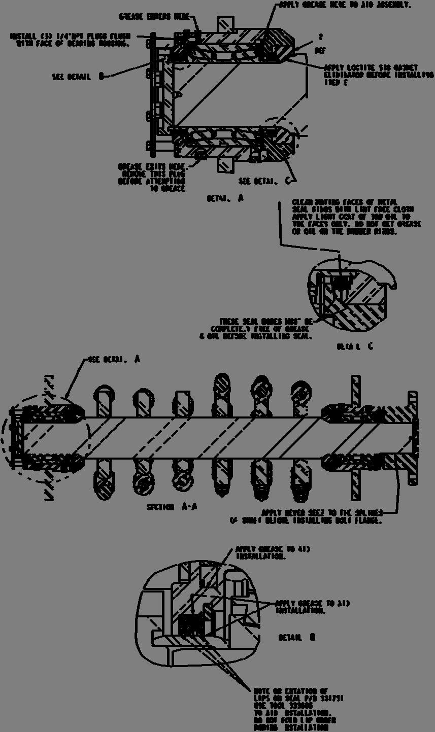
Fig. 68: Breaker shaft assembly and disassembly
Metal face
Metal ring
Rubber ring
BI632977
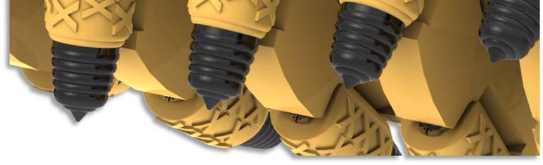
How to remove the breaker bit
To remove the breaker bit from the breaker shaft bit holder proceed as follows (Fig. 69):
Remove the external retaining rings from the shank end of the bit with a pair of external retaining ring pliers.
Remove the bit from its holder. If the bit will not pull easily from its holder, it may be necessary to insert a bar behind the shank end of the bit and pry it out.
IMPORTANT! If the bit will not pull easily from its holder, it may be necessary to insert a bar behind the shank end of the bit and pry it out.
How to install the breaker bit
To install the breaker bit in the breaker shaft bit holder proceed as follows (Fig. 86):
Clean any dirt or debris from inside or around the holder and insert the shank end of the bit into the bit holder.
Install the external retaining rings (two per bit) on the shank end of the bit with a pair of external retaining ring pliers. Ensure that the retaining ring is completely seated inside grooved area of the bit.
Fig. 69: Breaker bit removal and installation
Bit holder Retaining rings
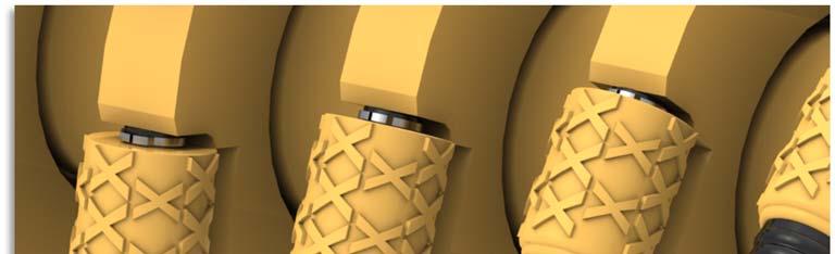
Breaker bit