BI005692
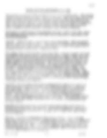
SWIVEL RETURN MECHANISM (L. P. 256) The machine is equipped with swiveling devices on each walking shoe. The purpose of these swivels is to protect the walking mechanism. When the greater part of the shoes is on firm dry level ground, slippage is not noticeable but conditions will arise when one shoe may be on solid fotting and the other will sink in or slip back. This would tend to rotate the entire machine around the shoe which h holding. Such a condition imposes excessive stresses in the walking mechanism. nlustration of walking shoe swivel assembly view No. 1 and 2, L. P. 256, shows the swiveling device installed on the shoes and its operation is described in the following paragraphs. View No. 1 shows the shoe in its normal or starting position, which 18 parallel with the center line of the machine. This position is brought about automatically when the Ihoes are raised off the ground through the action of the swivel return mechanism which is described in detail as follows: The walking shoe (1) has mounted on its upper side, a swivel assembly (2) which 11 attached to the shoe by pin (3), allowing the shoe to rotate in either direction. The other end of the swivel assembly is prevented from lifting off the shoe by a keeper casting (4) which is bolted to the shoe and has a projecting flange or lip which hooks over the swivel assembly. The swivel assembly is provided with two journal bearings (5) and (6) in which the walking arm yoke casting (7) 11 mounted. Journal bearing (5) is cast integral with the swivel casting, while journal bearing (6) is cast separate, and is bolted to the swivel casting. Thil type design is necessary for assembly purposes. The walking arm yoke casting (7) 11 also made with two journal bearings in which the walking arm is mounted. These two sets of journal bearings form a universal joint which allows the shoe to tilt both sidewise and lengthwise. Attached to the underside of the swivel casting are two slide blocks which are made of special composition having a low coefficient of friction, 10 that they will slide readily under pressure. These slide blocks bear on finished slide plates (8) welded to the top of the shoe, the contact surfaces being grease packed. The lubricant is prevented from escaping by means of a grease retainer entirely surrounding the slide plates on the shoe. The slide plate covers (9) protect the slide plates, preventing dirt and moisture accumulating on the bearing surfaces. Extending forward on the shoe swivel pin (3) is a part of the swivel assembly known as the Swivel Return Mechanism. This return mechanism consists of an adjusting screw (10), a spring (II), a plunger (12), a roller (13), and a roller track or cam (14). View No. 1 shows the walking shoe in the normal position, which is brought about automatically when the shoe is raised off the ground. This is accomplished by the action of the spring (11), causing the roller (13) to seek the low point or center of the cam (14). When 1.1 the normal position, the center line of the shoe coincides with the center line of the swivel assembly which is always held parallel to the upper frame by the walking arm. No. 1017 III
- 2 -
9/1955


