BI005074
2. Also adjust the adjusting screw to shorten the B dimension ;ji H inch each time the spring is readjusted. This will preven t the cy linder from bottoming out and possibly preventing the brake from setting.
:3. Release brake, check for equal clearance of lining to drum, and readjust jaw set screws for 1/64 inch clearance.
2. Unbolt the brake support bracket and slide the
complete brake assembly from the brake drum. Note, ifused, the thickness and location of the shims under the bracket, so that when the bracket is remounted, the brake will align properly with the brake drum. ;l. Remove the spring rod bolt special nut. rod bolt, and spring. 4. Unpin and remove the air cylinder from the
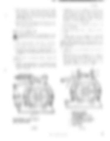
Brake style 6 (figure 49)
brake.
L";,. CAUTION: Prior to working on any . . brakes, observe the following precautions: 1. Place walking shoes and bucket on ground.
2. De-energize, lock out and tag all controls. 3. Set all brakes except those being worked on. A
minimum of one brake per unit should always be set. To disassemble style 6 brakes (figure 49) proceed as follows: 1. Remove the spring rod bolt nut. Back off on the rod bolt special nut until all tension is removed from the spring.
'J.
Unpin and remove the brake lever adjusting screw assembly from the brake jaw (figure .)()).
NOTE: The adjusting screzo must be removed from the lever pin and then the lever pin removed. 6. Unpin and remove the brake lever from the brake jaw. 7. Turn the brake jaw adjusting screws all the way in, then remove the jaw to bracket pins and remove the jaw and shoe as an assembly (figure Gl). Separate the jaw and shoe by removing the mounting bolt.
-,~,,-
1.
STYLE 6
2.
DISASSEMBLY , REASSEMBLY AND ADJUSTMENT
3. 4. 5.
FIGURE 49
SCREW PIN, COTTER PIN AND WASHER FULCRUM PIN, COTTER PIN AND WASHERS ADJUSTING SCREW ASSEMBLY ROD END PIN, COTTER PIN AND WASHERS BRAKE LEVER FIGURE 50
BUCYRUS-ERIE COMPANY, 1985
47


