7 minute read
Brakes -Style 6


2. Also adjust the adjusting screw to shorten the
B dimension ;ji Hinch each time the spring is readjusted. This will prevent the cylinder from bottoming out and possibly preventing the brake from setting. possibly
:3. Release brake, check for equal clearance oflining to drum, and and readjust jaw set screws for 1/64 1/64 inch clearance.
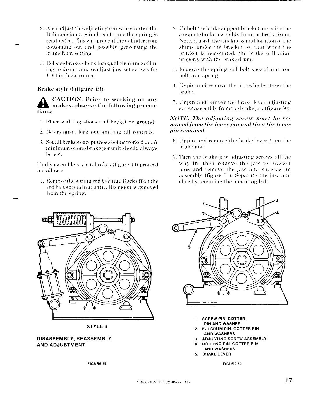
Brake style 6 (figure 49)
L";,. CAUTION: Prior to working on any .. brakes, observe the following precautions:
1. Place walking shoes and bucket on ground.
2. De-energize, lock out and tag all controls.
3. Set all brakes except those being worked on. A minimum ofone brake per unit should always be set. except
To disassemble style 6 brakes (figure 49) proceed as follows:
1. Remove the spring rod bolt nut. Back offon the rod bolt special nut until all tension is removed from the spring. 2. Unbolt the brake support bracket and slide the complete brake assembly from the brake drum.
Note, ifused, the thickness and location of the shims under the bracket, so that when the bracket is remounted, the brake will align properly with the brake drum. and from so is
;l. Remove the spring rod bolt special nut. rod bolt, and spring.
4. Unpin and remove the air cylinder from the brake.
'J. Unpin and remove the brake lever adjusting screw assembly from the brake jaw (figure .)()).
NOTE: The adjusting screzo must be removed from the lever pin and then the lever pin removed. then
6. Unpin and remove the brake lever from the brake jaw.
7. Turn the brake jaw adjusting screws all the way in, then remove the jaw to bracket pins and remove the jaw and shoe as an assembly (figure Gl). Separate the jaw and shoe by removing the mounting bolt. an mounting
STYLE 6
DISASSEMBLY, REASSEMBLY
AND ADJUSTMENT
FIGURE 49 1. SCREW PIN, COTTER PIN AND AND WASHER WASHER 2. FULCRUM FULCRUM PIN, COTTER PIN AND WASHERS 3. ADJUSTING SCREW ASSEMBLY 4. ROD END PIN, COTTER PIN AND WASHERS 5. BRAKE LEVER
FIGURE 50
3 3
4 4
1. 1. ARM ARM AND AND SHOE SHOE ASSEMBLY ASSEMBLY 2. 2. SET SET SCREW SCREW 3. 3. FULCRUM FULCRUM PIN PIN AND AND JAM JAM NUTS NUTS 4. 4. RETAINER RETAINER 5. 5. BRACKET BRACKET 6. 6. SPACER SPACER WASHERS WASHERS
FIGURE FIGURE 51 51
NOTE: NOTE: When When removing removing the the jaw jaw to to bracket bracket pins, pins, note note the the thickness thickness and and position position of of the the spacer spacer washers washers so so that that when when the the brahe brahe is is reassembled reassembled the the jaws jaws will will be be centered. centered.
To To remove remove the the brake brake drum drum from from the the motor motor (fig(figure ure bend bend down down the the locking locking ear ear of of the the nut nut lock lock plate plate and and unscrew unscrew the the nut nut about about two two full full turns. turns. 1)0 1)0 not not remove remove the the nut. nut. U"e U"e a a puller puller to to break break the the drum drum loo"e loo"e from from the the motor motor shaft. shaft. Remove Remove the the nut, nut, lock lock plate, plate, drum drum and and key key from from the the motor motor "haft. "haft.
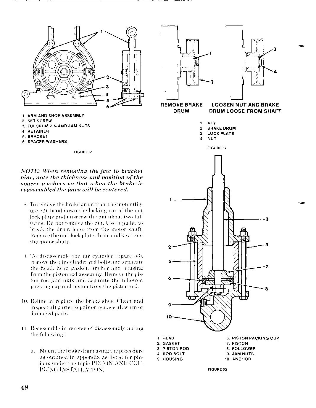
9. 9. To To disa"semble disa"semble the the aIr aIr cylinder cylinder (figure (figure f);)), f);)), remove remove the the air air cylinder cylinder rod rod bolts bolts and and separate separate the the head, head, head head gasket, gasket, anchor anchor and and housing housing from from the the piston piston rod rod assembly. assembly. Remove Remove the the pispiston ton rod rod jam jam nuts nuts and and separate separate the the follower, follower, packing packing cup cup and and piston piston from from the the piston piston md. md.
10. 10. Reline Reline or or replace replace the the brake brake shoe. shoe. Clean Clean and and inspect inspect all all parts. parts. Hepair Hepair or or replace replace all all worn worn or or damaged damaged parts. parts.
11. 11. Heassemble Heassemble in in reverse reverse of of disassembly disassembly noting noting the the following: following:
a. a. Mount Mount the the brake brake drum drum using using the the procedure procedure as as outlined outlined in in appendix appendix as as listed listed for for pinpinions ions under under the the topic topic PINION PINION AND AND COUCOU-
PLING PLING INSTALLATION. INSTALLATION.
REMOVE REMOVE BRAKE BRAKE DRUM DRUM LOOSEN LOOSEN NUT NUT AND AND BRAKE BRAKE DRUM DRUM LOOSE LOOSE FROM FROM SHAFT SHAFT
1. 1. KEY KEY 2. 2. BRAKE BRAKE DRUM DRUM 3. 3. LOCK LOCK PLATE PLATE 4. 4. NUT NUT
FIGURE FIGURE 52 52
2 2
S---i--H S---i--H 4 4
7 7
9-----' 9-----'
10 10
1. 1. HEAD HEAD 2. 2. GASKET GASKET 3. 3. PISTON PISTON ROD ROD 4. 4. ROD ROD BOLT BOLT 5. 5. HOUSING HOUSING 8 8
6. 6. PISTON PISTON PACKING PACKING CUP CUP 7. 7. PISTON PISTON 8. 8. FOLLOWER FOLLOWER 9. 9. JAM JAM NUTS NUTS 10. 10. ANCHOR ANCHOR
FIGURE FIGURE 53 53
b. b. When When bolting bolting brake brake jaws jaws to to brake brake shoes shoes (figure (figure :")4), :")4), brake brake shoe shoe is is to to clamp clamp against against brake brake jaw jaw flange flange sufficiently sufficiently tight tight so so that that the the shoe shoe can can adjust adjust itselfto itselfto the the brake brake drum drum and and still still not not drag drag on on the the drum drum when when the the brake brake is is released. released.
2 2 3 3 4 4 S S __ ---'00,-
6 6
1. 1. ARM ARM AND AND SHOE SHOE ASSEMBLY ASSEMBLY
2. 2. SET SET SCREW SCREW 3. 3. FULCRUM FULCRUM PIN PIN AND AND JAM JAM NUTS NUTS 4. 4. RETAINER RETAINER 5. 5. BRACKET BRACKET 6. 6. SPACER SPACER WASHERS WASHERS
FIGURE FIGURE 54 54
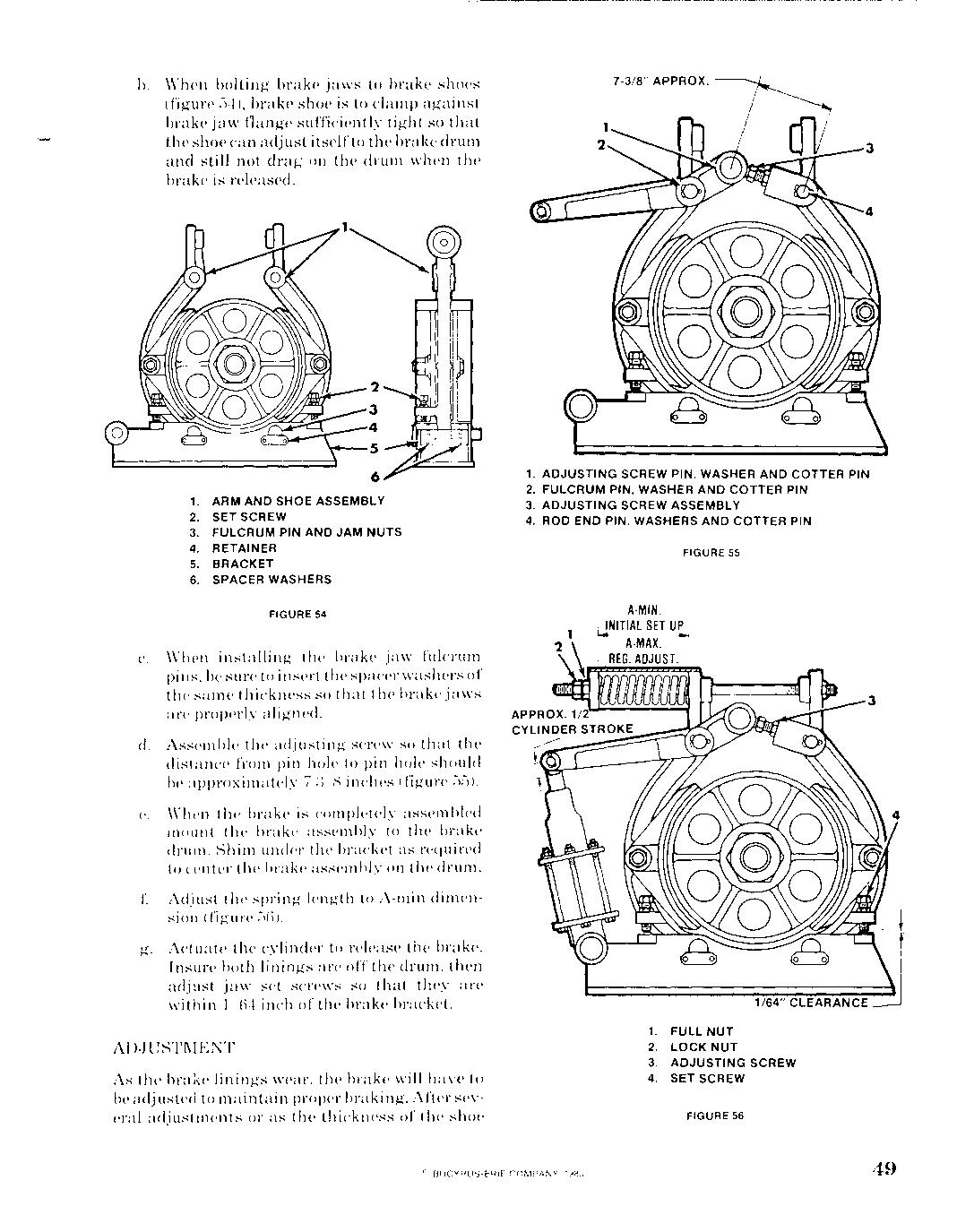
c. c. When When installing installing the the brake brake jaw jaw fulcrum fulcrum pins. pins. be be sure sure to to insert insert the the spacer spacer washers washers of of the the same same thickness thickness so so that that the the brake brake jaws jaws arc arc properly properly aligned. aligned.
d. d. Assemble Assemble the the adjusting adjusting screw screw so so that that the the distance distance from from pin pin hole hole to to pin pin hole hole should should be be approximately approximately 7-:lH 7-:lH inches inches (figure (figure :'>S). :'>S).
e. e. When When the the brake brake is is completely completely assembled assembled mount mount the the brake brake assembly assembly to to the the brake brake drum. drum. Shim Shim under under the the bracket bracket as as required required to to center center tIl(' tIl(' brake brake assembly assembly on on the the drum. drum.
f. f. Adjust Adjust the the spring spring length length to to A-min A-min (limen(limension(figure sion(figure ;-)(i). ;-)(i).
g. g. Actuate Actuate the the cylinder cylinder to to release release the the brake. brake.
Insure Insure both both linings linings are are off off the the drum, drum, then then adjust adjust jaw jaw set set screws screws so so that that they they are are within within 1/()4 1/()4 inch inch of of the the brake brake bracket. bracket.
AI),JUSTMENT AI),JUSTMENT
As As the the brake brake linings linings wear, wear, the the brake brake will will have have to to be be adjusted adjusted to to maintain maintain proper proper braking. braking. After After sevseveral eral adjustments adjustments or or as as the the thickness thickness of of the the shoe shoe
1. 1. ADJUSTING ADJUSTING SCREW SCREW PIN, PIN, WASHER WASHER AND AND COTTER COTTER PIN PIN 2. 2. FULCRUM FULCRUM PIN, PIN, WASHER WASHER AND AND COTTER COTTER PIN PIN 3. 3. ADJUSTING ADJUSTING SCREW SCREW ASSEMBL ASSEMBLY Y 4. 4. ROD ROD END END PIN, PIN, WASHERS WASHERS AND AND COTTER COTTER PIN PIN
FIGURE FIGURE 55 55
A-MIN. A-MIN.
A-MAX. A-MAX. I I REG. REG. AllJUST. AllJUST. I I
3 3
1. 1. FULL FULL NUT NUT
2. 2. LOCK LOCK NUT NUT 3. 3. ADJUSTING ADJUSTING SCREW SCREW 4. 4. SET SET SCREW SCREW
FIGURE FIGURE 56 56