2 minute read
Boom


CHAPTER 1 MECHANICAL MAINTENANCE MAINTENANCE
SECTION 4- FRONT END EQUIPMENT
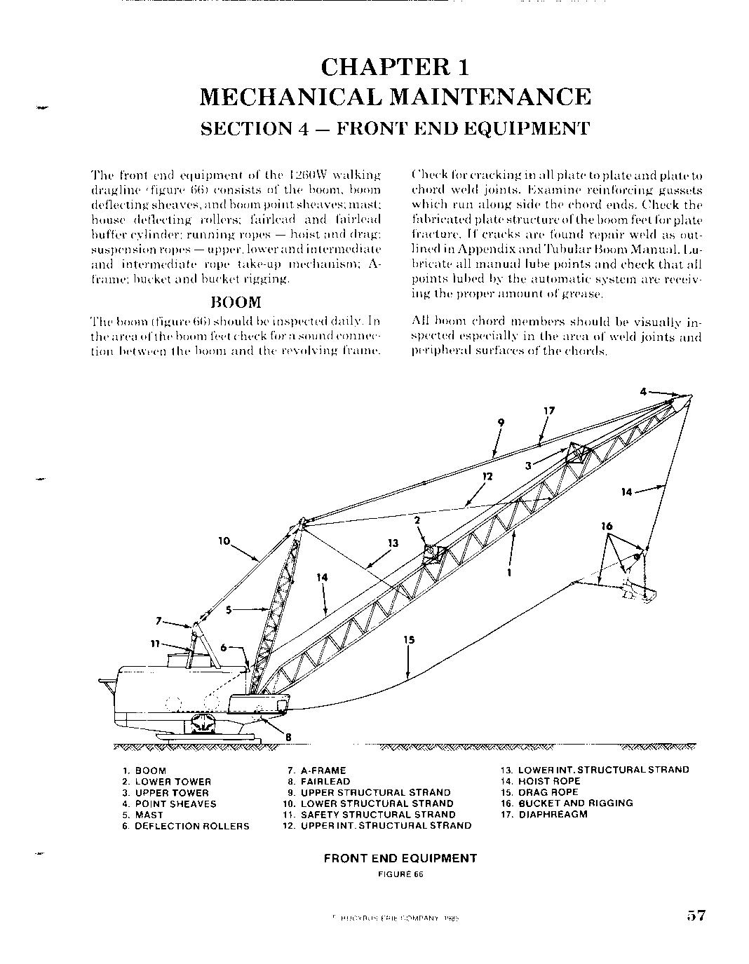
The front end equipment of the 1260W walking dragline (figure (6) consists of the boom, boom deflecting sheaves, and boom point sheaves; mast; house deflecting rollers; fairlead and fairlead buffer cylinder; cylinder; running ropes - hoist and drag; suspension ropes - upper, lower and intermediate and intermediate rope take-up mechanism; Aframe; bucket and bucket rigging.
BOOM
The boom (figure (6) should be inspected daily. In the area ofthe boom feet check for a sound connection between the boom and the the revolving frame. Check for cracking in all plate to plate and plate to chord weld joints. Examine reinforcing gussets which run along side the chord ends. Check the fabricated plate structure ofthe boom feet for plate fracture. If cracks are found repair weld as outlined in Appendix and Tubular Boom Manual. Lubricate all manual lube points and check that all points lubed by the automatic system are receiving the proper amount of grease. and boom fracture. as Appendix
All boom chord members should should be visually inspected spected especially in the area of weld joints and peripheral peripheral surfaces of the chords.
1. BOOM 2. LOWER TOWER 3. UPPER TOWER 4. POINT SHEAVES 5. MAST MAST 6. DEFLECTION ROLLERS
7. A-FRAME 8. FAIRLEAD 9. UPPER STRUCTURAL STRAND 10. LOWER STRUCTURAL STRAND 11. SAFETY STRUCTURAL STRAND 12. UPPER INT. STRUCTURAL STRAND
FRONT FRONT END EQUIPMENT
FIGURE 66 13. LOWER INT. STRUCTURAL STRAND 14. HOIST ROPE 15. DRAG ROPE 16. BUCKET AND RIGGING 17. DIAPHREAGM
The boom point and deflection sheaves should also be inspected at this tinw. Refer to the topics on these items for inspection procedures.
To assist in locating cracks in the boom, the main longitudinal chords and apex chords are filled with pressurized dry air. The air pressure in the chords is monitored by gauges and pressure switches. If the pressure drops below 7S PSI the pressure switch will close and activate a warning device in the operator's cab. Ifthe warning device sounds the machine should be stopped and the sourceoftheleak located and repaired beforefurther operation of the machine.
If any cracks are noted in the boom refer to the Tubular Boom Manual for the correct repair procedures.
'2 3,4

10
9
14 J __
LATEST STYLE
1. UPPER TOWER 2. TOWER BUSHING 3. INNER THRUST WASHER 4. OUTER THRUST WASHER 5. TOWER SHEAVE 6. SHEAVE BUSHING 7. SHEAVE THRUST WASHER 8. SHEAVE SHAFT 9. SHAFT BRACKET 10. SHAFT RETAINER 11. ROPE GUIDE 12. LOWER STRUCTURAL STRAND 13. UPPER STRUCTURAL STRAND 14. BOOM 15. OUTER SPACER 16. INNER SPACER 17. CLAMP COLLAR
EARLIER STYLE
14
BOOM UPPER DEFLECTION SHEAVE TOWER
FIGURE 67
13 !
LATEST STYLE
10
13 9
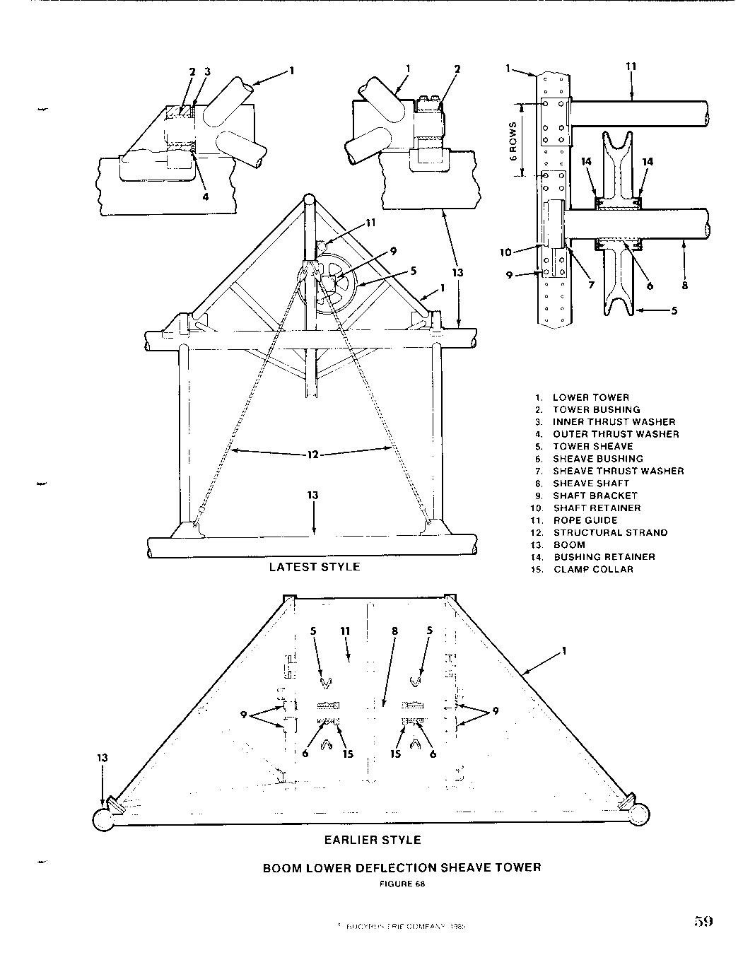
1. LOWER TOWER 2. TOWER BUSHING 3. INNER THRUST WASHER 4. OUTER THRUST WASHER 5. TOWER SHEAVE 6. SHEAVE BUSHING 7. SHEAVE THRUST WASHER 8. SHEAVE SHAFT 9. SHAFT BRACKET 10. SHAFT RETAINER 11. ROPE GUIDE 12. STRUCTURAL STRAND 13. BOOM 14. BUSHING RETAINER 15. CLAMP COLLAR
EARLIER STYLE
BOOM LOWER DEFLECTION SHEAVE TOWER
FIGURE 68