BI005074
~
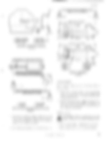
MEASURE DISTANCE BETWEEN PIN HO~ES (ARMS CLOSED MAXIMUM)
1
1 MEASURED DISTANCE
2 1. BRAKE SUPPORT 2. SHIM OR SPACER 3. BRAKE DRUM
4. DRUM KEY 5. NUT LOCK PLATE 6. MOTOR NUT MEASURED DISTANCE
SUPPORT AND DRUM REMOVAL
5
FIGURE 34
4
A MIN.
B MAX.
r-------------------<-j -----------<-j r--J
8 9
MEASURED DISTANCE PLUS ONE INCH
1. 2. 3. 4. 5.
6. 7. 6. 9. 10.
BRAKE ARM NUT ROO BOLT NUT ROD BOLT
SPRING GUIDE ANCHOR PLATE ROD END JAM NUT SPRING
SPRING ASSEMBLY
MEASURE DISTANCE BETWEEN PIN
,+-_ _..,., HOLES (ARMS SPREAD MAXIMUM) A---f"'''''
FIGURE 36
There are two adjustments on the brakes (figure :l8) as follows:
I~"---J 1-"--3
MEASURE DISTANCE BETWEEN PIN HOLES (ARMS SPREAD MAXIMUM)
3 1. ROD END 2. JAM NUT
3. BRAKE ARM 4. ADAPTER
AIR CYLINDER ROD END INSTALLATION
1. When the spring length reaches A-max dimension with the brake set, tighten the adjusting rod bolt nuts until the spring length is A-min dimension. 2. With the brake released, adjust the set screws on the sides of the brake support to obtain 1 16 inch clearance at the top and bottom between the lining and the drum.
FIGURE 35
Brake style 7 12. Activate cylinder to release brake and adjust set screws on the sides of the support to obtain 1/16 inch clearance at the top and bottom between the lining and drum. 1:3. Install all guards and lubricate all lube points.
h. CAUTION: Prior to working on any . . brake, observe the following precautions: 1. Place walking shoes and bucket on ground. 2. De-energize, lock out, and tag all controls.
© BUCYRUS-ERIE COMPANY, 1985
41


