OPERATING INSTRUCTIONS RH 340 Inspection and servicing Function Die Schmierung erfolgt von der Schmierpumpe (2, Fig. 3-127:) mit angebautem Fettfaß, die über Leitungen den Schmierstoff zu den Hauptverteilern fördert. Die Steuerung für die Schmieranlage befindet sich auf der Platte (3)
Fig. 3-129:
As soon as the grease container is empty, the BCS (2, Fig. 3-130:) gives a warning signal. In the event of a fault, the "dumping" function is switched off automatically after 15 min. Work can be continued when the grease container is filled with grease. Fig. 3-127:
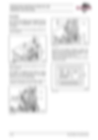
(for machnes with automatic greasing of the track rollers, optional) The grease is. pumped by the pumps (1 and 3, Fig. 3-128:) via greasing lines from the grease container to the main distributors on the superstructure and on the undercarriage. The control elements of the lubricating system are installed on the panels (3 and 21, Fig. 3-129:).
Fig. 3-130:
Fig. 3-128:
3-104
BA RH340(3 720 350.00)-EN
