BI017764
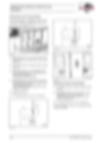
OPERATING INSTRUCTIONS RH 340 OPeration Switching on the circuit breaker The circuit breaker is accessible in field II after opening the switchgear cabinet door (Fig. 2-74:).
Fig. 2-76:
Fig. 2-74:
 Slip switch lever (11, Fig. 2-75:) pointing upwards onto the actuating shaft of the circuit breaker (1).  Pull locking element outwards against spring pressure.  Using switch lever (11), turn actuating shaft (drive A) clockwise from position I by ca. 180° downwards to position II. This tensions the cut-out spring.  Using switch lever (11, Fig. 2-76:), turn actuating shaft counter-clockwise from position II by 180° upwards to position I. This tensions the cut-in spring and the circuit breaker is switched on.
Fig. 2-77:
 Engage locking ring.
 Using switch lever (11, Fig. 2-75:), turn actuating shaft ca. 20° counter-clockwise. This releases the cut-out spring. The circuit breaker is switched off.
 The indicator lamp (1, Fig. 2-77:) comes on.
Switching off the circuit breaker  Pull locking element outwards against spring pressure.
 The indicator lamp (1, Fig. 2-77:) goes out. Further information is given in the attached leaflet on circuit breakers.
Fig. 2-75:
2-52
BA RH340(3 720 790.01)-EN
