BI017764
OPERATING INSTRUCTIONS RH 340 OPeration EMERGENCY STOP pushswitch
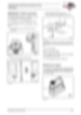
above the service lift (6, Fig. 2-27:). The pull switch is is operated by a string (5).
The entire electrical system is switched off with the EMERGENCY STOP pushswitches. In an emergency, press the EMERGENCY stop. The EMERGENCY STOP pushswitches are located
in the control column in the driver's cab (31, Fig. 2-25:)
Fig. 2-27:
The electrical system can be switched on after the EMERGENCY – OFF switches are activated, to do so: Â Pull out switches. Switch – servicing works Fig. 2-25:
in the control cabinet (3, Fig. 2-26:)
In an emergency the electric motor can switched off with switch (4, Fig. 2-26:). Â In an emergency, press in switch (4).
Windscreen washer The reservoir of the windscreen washing system (1, Fig. 2-28:) is installed in the cab module. For the reservoir capacity refer to the "Refilling quantities - Other" table.
Fig. 2-26:
Fig. 2-28:
BA RH340(3 720 790.01)-EN
2-19
