BI017764
OPERATING INSTRUCTIONS RH 340 Inspection and servicing Function The grease is pumped by the pump (1, Fig. 3-97:) via greasing lines from the grease container to the main distributors on the superstructure and on the undercarriage. The control elements of the lubricating system are installed on the panels (3).
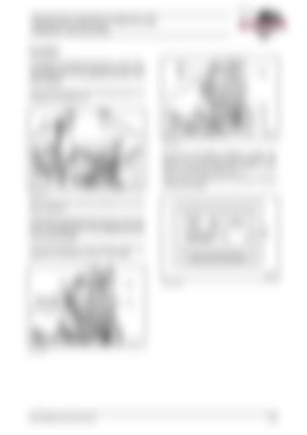
Fig. 3-99:
As soon as the grease container is empty, the BCS (2, Fig. 3-100:) gives a warning signal. In the event of a fault, the "dumping" function is switched off automatically after 15 min. Work can be continued when the grease container is filled with grease. Fig. 3-97:
(for machines with automatic greasing of the track rollers, optional) The grease is pumped by the pumps (1 and 3, Fig. 3-98:) via greasing lines from the grease container to the main distributors on the superstructure and on the undercarriage. The control elements of the lubricating system are installed on the panels (3 and 21, Fig. 3-99:).
Fig. 3-100:
Fig. 3-98:
BA RH340(3 720 790.01)-EN
3-85
