3 minute read
Fuel transfer pump
WARNING
Diesel fuel is flammable. Do not puncture or burn the containers. Follow the instructions provided on the containers for stocking and handling.
Always extinguish smoking materials and free flames prior to checking or refuelling the fuel reservoir, replacing filters or opening the condensation draining plug, due to the presence of highly flammable fumes.
Do not refuel with the engine running. Do not use matches, cigarette lighters or free flame torches as a source of light on the machine.
WARNING
Never use gasoline, solvent or other flammable fluid to clean parts. Use exclusively qualified, nonflammable, non-toxic commercial solvents.
NOTE: use decanted fuel for refuelling. It is recommended that the refuelling is made at the end of the working day, thus avoiding condensations during overnight parking. Do not run-out of fuel in the reservoir. This would cause the entry of air in the fuel system, making its bleeding necessary.
1
4
F12671
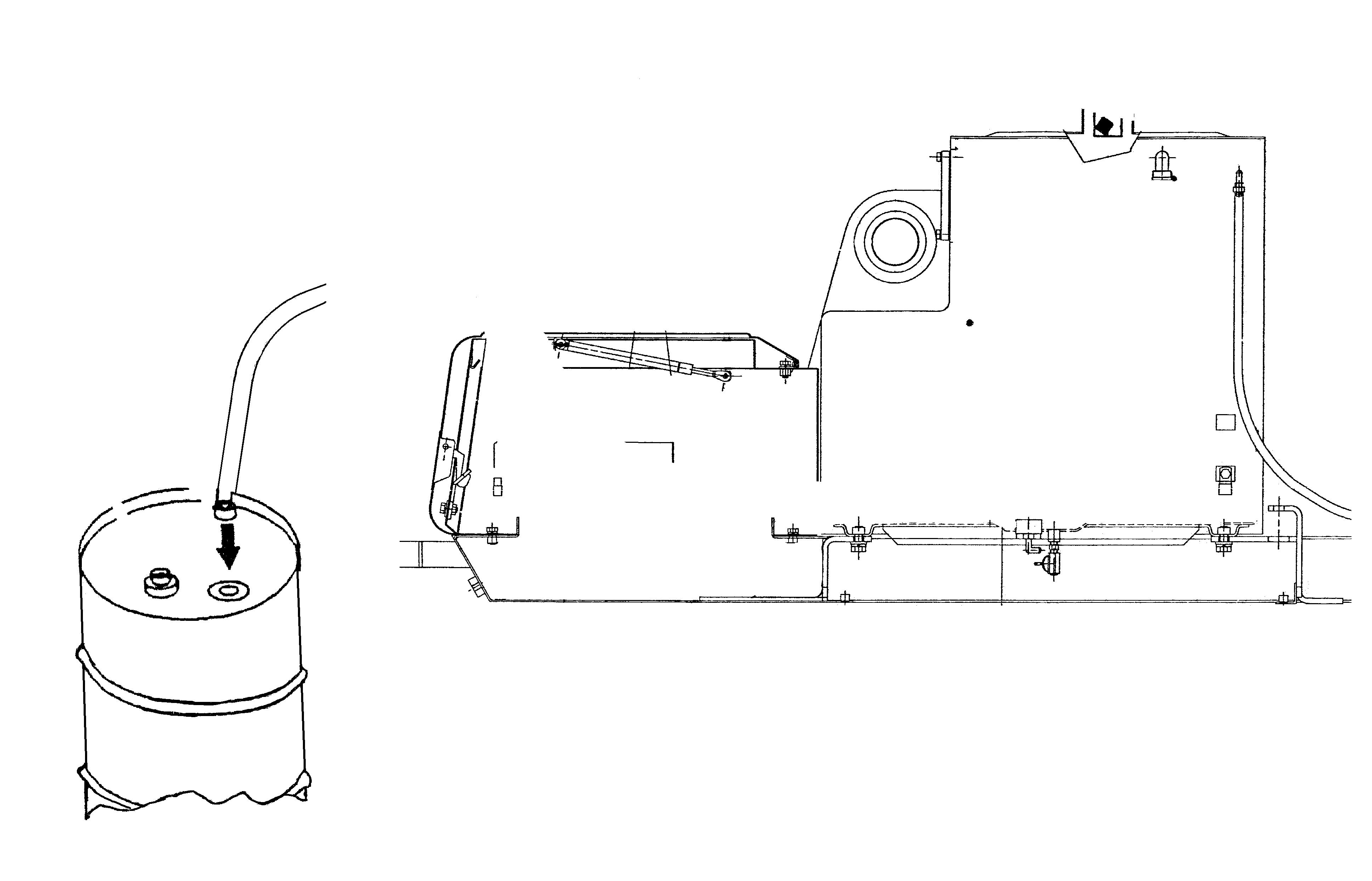
• The fuel transfer pump is located inside the central compartment. It is reached by lifting panel (4).
3
F8371 27401 6-30060 GB
• The filling of the fuel reservoir using the electric fuel transfer pump is made in the following manner:
-remove cap (1) from the fuel reservoir;
-unwind hose (11) until its tip with filter (6) can be dipped into fuel container (10);
-move switch (8) located on pump (5) from position (OFF) to position (ON);
-check on level sight indicator (1) or dipstick (3) the filling of the reservoir;
-once the desired fuel level is reached in reservoir (9), move switch (8) from position (ON) to position (OFF);
-install cap (1) on the fuel filler neck; -drain completely the residual fuel from hose (11), then wind it up and store it in its place, inside the tool storing compartment.
-then, close tool compartment panel (4).
WARNING
Check that there are no traces of fuel inside the tool storing compartment. If positive, mop it up with a rag and let it evaporate. This is to prevent the danger of fires.
IMPORTANT: when rewinding the hose, pay attention to avoid kinking it, to prevent damages and leakages.
10 6 11 9 4
1
5

27401 6-30060 GB
7

8
OFF ON
F13652
• The fuel transfer pump has its own electrical circuit, protected by a 5 Amp fuse (7). In the event the fuse blows, thus preventing the pump from operating, only replace it with one of the same rating.
If the problem keeps occurring investigate the cause.
• The end of hose (11) is fitted with mesh filter (6) which, in case of clogging, preventing the flow of fuel, must be cleaned. In case the cleaning is ineffective, replace the filter.
NOTE: in the event the machine is not originally equipped with this variant, the User can contact a Dealer for the its installation. IMPORTANT: The use of non genuine components can involve the risk of malfunctions of the machine and a reduction of the safety limits during its operation.
10 6 11 9 4
1
5
7

8

OFF ON
F13652 27401 6-30060 GB
27401 6-30060 GB
COPYRIGHT BY CASE SA 18, place des Nymphéas ZI Paris Nord II - 93420 Villepinte France
Reproduction of text or illustrations, in whole or in part, is strictly prohibited
6-30060 GB - 11 - 2001
27401 6-30060 GB
CASE TECHNICAL MANUALS
You can obtain manuals on the operation, maintenance and repair of your machine from your CASE Dealer. To ensure quick and efficient service, consult your CASE Dealer for assistance in ordering the correct manuals for your machine. Your CASE Dealer can deal with orders for operator’s manuals, parts catalogues and service manuals. Always give the type and serial number of your machine so that your CASE Dealer can supply you with the correct manuals for your machine.
Printed in France


