7 minute read
HYDRAULIC SYSTEM


HYDRAULIC SYSTEM Service specifications
Reservoir fluid level check..........................................Every 10 hours or every day Replacing the hydraulic reservoir filters..................When the warning lamp on the instrument comes on or every 2000 hours Replacing the anti-surge valve filter..............................................Every 500 hours Replacing the brake system filter..................................................Every 500 hours Replacing the selection block circuit filter.....................................Every 500 hours Replacing the return circuit filter....................................................Every 500 hours Replacing the hydraulic system filter.............................................Every 500 hours Replacing the breather/filler cap.................................................Every 2000 hours Drain system...............................................................................Every 2000 hours Reservoir capacity....................................................................................180 liters Total System Capacity..............................................................................288 liters Type of oil......................................................................See “Fluids and lubricants”
Reservoir fluid level
1. Park the machine on flat, level ground. 2. Retract the bucket cylinder rod and dipper cylinder rod completely. 3. Raise the stabilizers and the dozer blade (if equipped). 4. Lower the attachment to the ground. 5. Stop the engine and remove the starter switch key.
Replacing the breather/ filler cap
Tools required
-A cross-headed screwdriver
PG02634 Remove the retaining chain and then remove the breather/filler cap from the reservoir. Install a new seal and breather/ filler cap. Install the chain.

PH00414 The oil must be between the two marks (1) and (2) on the gauge. If not, add fluid. See “Filling” .
Replacing the hydraulic reservoir filters
Tools required
-One 10 mm wrench for hexagonal socket head screws -One filter strap wrench -One oil can
STEP 1

PG02634 Loosen the reservoir pressure release plug two or three turns and then retighten.
STEP 2
PH07635 Place a container of a suitable capacity under the filters. Loosen the filters using a filter wrench, then unscrew them manually.
STEP 4
Apply a thin coat of oil on the new filter seals.
STEP 5

PH07635 Clean the area around the filter heads.

PH07635 Install the new filters. Turn the filters until the seals come into contact with the filter heads, then turn the filters an extra half turn by hand to tighten. IMPORTANT: Do not use a filter wrench. Overtightening can damage the seals and the filters.
STEP 6

CD99N017 When the filters have been changed, start up the engine at idle speed (“LOW” mode) and make sure that the filter restriction warning lamp on the instrument panel is not on. NOTE: After operating the machine, check for leaks.

Changing the hydraulic fluid
Changing the CASE hydraulic fluid consists of systematically draining the main components (reservoir, pumps, cylinders, control valves, hydraulic motors and oil cooler). We advise you to contact your CASE Dealer.

Draining
Tools required
-One 10 mm wrench for hexagonal socket head screws -One 12 mm wrench for hexagonal socket head screws -One 17 mm wrench for hexagonal head screws
STEP 1
Park the machine on flat, level ground. Stop the engine and remove the starter switch key.
STEP 2
PG02634 Loosen the reservoir pressure release plug two or three turns.
STEP 3
Remove the left-hand access panel.
STEP 4
PG02904 Remove the reservoir drain plug and allow the fluid to flow out. NOTE: The reservoir capacity is 180 liters. Use a container of an adequate capacity.
Drain the other components by removing the supply and return fittings. Consult your CASE Dealer. NOTE: See “Replacing the hydraulic reservoir filters” if the filters need to be replaced.
Filling
Tools required
-One 10 mm wrench for hexagonal socket head screws -One 12 mm wrench for hexagonal socket head screws -One funnel (delivered with machine) -One 17 mm wrench for hexagonal head screws
STEP 1
PG02904 Install and tighten the reservoir drain plug.
STEP 3

PG02632 Clean the area around the cap and remove the breather/filler cap.

PG02628 Install the funnel, located in the tool box, and fill the reservoir with suitable hydraulic fluid.
STEP 4
PH00414 The fluid level must be between the two marks (1) and (2) on the gauge.
STEP 5 STEP 8

Lower the attachment to the ground and make sure that the dozer blade and the stabilizers (if equipped) are completely raised.
STEP 9
Stop the engine and remove the starter switch key.
STEP 10
PG02634 Remove the funnel, install the breather/ filler cap and tighten the pressure release plug.
STEP 6
Start up the machine and operate the attachment, swing and travel functions.
STEP 7
Retract the bucket cylinder rod and dipper cylinder rod completely.

PH00414 Check the fluid level. The fluid must be between the two marks (1) and (2) on the gauge. Add fluid, if necessary.
STEP 11
Install the left-hand access panel.
Replacing the anti-surge valve filter
Tools required
-One 10 mm wrench for hexagonal socket head screws -One 17 mm wrench for hexagonal head screws
STEP 1
1 2
CD99N001 Release the pressure in the hydraulic system. See “Releasing pressure in the hydraulic system” .
STEP 2
Remove the front left-hand access panel.
STEP 3
PE07332 Remove the spring (1) and the filter (2).
STEP 5
Install a new filter (2).
STEP 6
Install the spring (1) and tighten the plug.
STEP 7
Install the left-hand access panel. NOTE: After operating the machine, check for leaks.
PH00528 Place a container of a suitable capacity under the filter and then remove the antisurge valve plug.

Replacing the brake system filter and selection block circuit filter
Tools required
-One 24 mm wrench for hexagonal head screws
STEP 1 STEP 3
2

1

CD99N001 Release the pressure in the hydraulic system. See “Releasing pressure in the hydraulic system” .
STEP 2

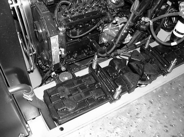
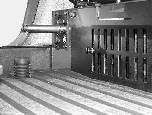
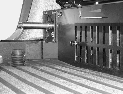
CD98G042 These filters are located at the rear of the cab floor. Place a container of a suitable capacity under one of the filters.
CD98F038 Loosen the casing (1) using the wrench, and remove the casing and the filter (2) manually.
STEP 4
Clean the casing and install a new filter.
STEP 5
Manually tighten the casing as far as the stop and then loosen one quarter turn.


CD98G042 CD00B012
Repeat Steps 2 to 5 for the other filter. NOTE: After operating the machine, check for leaks. Remove the plastic plug.
STEP 3
Replacing the return circuit filter
Tools required
-One 5 mm wrench for hexagonal socket head screws
STEP 1
1 2
4
3

CD99N001 Release the pressure in the hydraulic system. See “Releasing pressure in the hydraulic system” .
PDH1126 Remove the screws (1) and the cover (2). Then remove the filter (3).
STEP 4
Install a new filter (3).
STEP 5
Check the condition of seal (4) and replace it if necessary.
STEP 6
Install the cover (2) and the screws (1).
STEP 7
Install the plastic plug. NOTE: After operating the machine, check for leaks.
Replacing the hydraulic system filter
Tools required
-One 10 mm wrench for hexagonal socket head screws
STEP 1 STEP 2
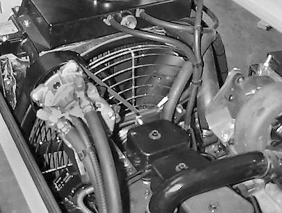
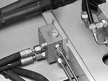
CD97K007 This filter is located at the bottom of the valve bank partition. Place a container of a suitable capacity under the filter and then remove the filter plug.
STEP 3
1 2
CD99N001 Release the pressure in the hydraulic system. See “Releasing pressure in the hydraulic system” .

PE07332 Remove the spring (1) and the filter (2).
STEP 4
Install a new filter (2), install the spring (1) and tighten the plug. NOTE: After operating the machine, check for leaks.