14 minute read
PRE-STARTING PROCEDURE (CONT’D)


Control Console
NOTE: There is a control lock switch in the left console which deactivates the hydraulic control levers (joysticks and traction system) when the control console lock lever is raised. The console must be in the locked down position for the hydraulic control levers (joysticks and traction system) to operate.
NOTE: If the control lock switch does not deactivate the control levers when the console lock lever is raised, see your Bobcat dealer for service.

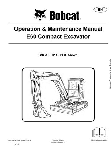
Mirror Adjustment
Figure64
Warning
AVOID INJURY OR DEATH
•Fasten seat belt, start and operate only from the operator’s seat.

•Never wear loose clothing when working near machine.
W-2135-1108
Perform the PRE-STARTING PROCEDURE. (See PRESTARTING PROCEDURE on Page 59.)
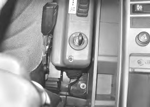
Figure65
Put control levers (Item 1) [Figure65] in the neutral position.
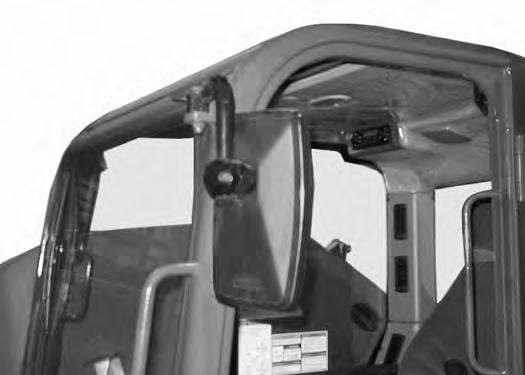
Figure66
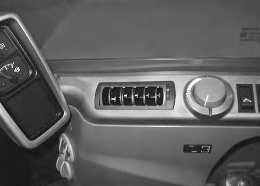
Rotate the engine speed control dial (Item 1) [Figure66] anticlockwise to low idle.
Warning
AVOID INJURY OR DEATH
When an engine is running in an enclosed area, fresh air must be added to avoid concentration of exhaust fumes. If the engine is stationary, vent the exhaust outside. Exhaust fumes contain odorless, invisible gases which can kill without warning.
W-2050-0807
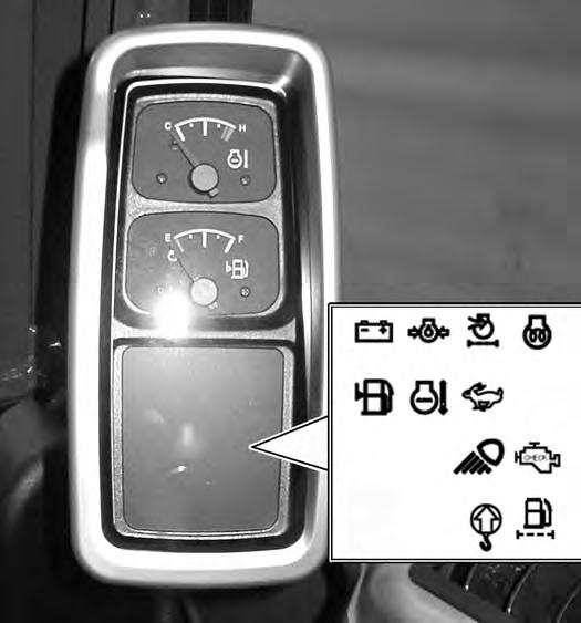
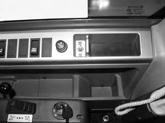
Turn the key (Item 1) [Figure67] to the ON position. If preheating is required, the air intake heater will automatically cycle. (The preheat icon will be ON while air intake heater is activated).
Turn the key to START and release the key when the engine starts. It will return to the ON position [Figure67]
Stop the engine if the warning lights and alarm do not go OFF. Check for the cause before starting the engine again.
Turn the key switch OFF to stop the engine.
Important
Do not engage the starter for longer than 15 seconds at a time. Longer use can damage the starter by overheating. Allow starter to cool for one minute before using starter again.
I-2034-0700
Warning
AVOID SERIOUS INJURY OR DEATH
•Engines can have hot parts and hot exhaust gas. Keep flammable material away.
•Do not use machines in atmosphere containing explosive dust or gases.
W-2051-0212
STARTING THE ENGINE (CONT’D)
Cold Temperature Starting
Warning
Avoid Injury Or Death
Do not use ether with glow plug (preheat) systems. Explosion can result which can cause injury, death, or severe engine damage.
W-2071-0907
If the temperature is below freezing, perform the following to make starting the engine easier:
•Replace the engine oil with the correct type and viscosity for the anticipated starting temperature. (See ENGINE LUBRICATION SYSTEM on Page 108.)
•Make sure the battery is fully charged:
•Install an engine heater, available from your Bobcat dealer.
NOTE: If the battery is discharged (but not frozen) a booster battery can be used to jump start the excavator. (See Using A Booster Battery (Jump Starting) on Page 115.)
Rotate the engine speed control dial (Item 1) [Figure68] half way between low and high engine speed.
Important
Do not engage the starter for longer than 15 seconds at a time. Longer use can damage the starter by overheating. Allow starter to cool for one minute before using starter again.
I-2034-0700
Release the key when the engine starts, it will return to the ON position.
Stop the engine if the warning lights and alarm do not go off. Check for the cause before starting the engine again.
When the engine speed increases, move the engine speed control dial (Item 1) [Figure68] to low idle position until the engine warms.
STARTING THE ENGINE (CONT’D)
Warming The Hydraulic System
Important
When the temperature is below -30°C (-20°F), hydrostatic oil must be warmed before starting. The hydrostatic system will not get enough oil at low temperatures and will be damaged. Park the machine in an area where the temperature will be above -18°C (0°F) if possible.
I-2007-0910
Let the engine run at least 5 minutes to warm the engine and hydraulic fluid before operating the excavator.
STOPPING THE ENGINE AND LEAVING THE EXCAVATOR
Procedure
Figure71
Stop the machine on level ground. Lower the work equipment and the blade to the ground [Figure71].
Turn the key switch to STOP (Item 1) [Figure73]
Disconnect the seat belt. Remove the key from the switch to prevent operation of machine by unauthorised personnel. Raise the control console lock lever and exit the machine.
Emergency Shut Off
Rotate the engine speed control dial (Item 1) [Figure72] to the low idle position.
Run the engine at idle speed for approximately 5 minutes to allow it to cool.
In case of emergency, move the switch (Item 1) [Figure74] in the STOP position.
The switch will return to the to the RUN position. Restart the engine using the start key.
Attachments
Installing And Removing The Attachment (Pin-On)
Installation
NOTE: Installation and removal of the bucket is shown. The procedure is the same for other attachments. Disconnect any hydraulic lines that are operated by hydraulic power before removing the attachments (breakers, auger, etc.).
Warning
AVOID INJURY OR DEATH
Stop the machine on a firm flat surface. When removing or installing attachments (such as a bucket), always have a second person in the operator’s seat, give clear signals and work carefully.
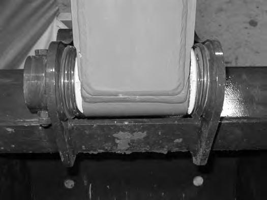
Installing the arm (Item 1) [Figure76] into the attachment.
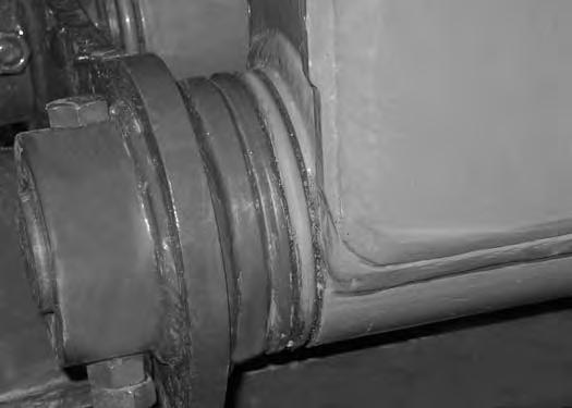
Before installing the attachment, make sure the four Orings (Item 1) [Figure75] are positioned over the attachment boss (as shown) so they are not damaged during installation.
Align the arm mounting hole with the attachment and install the pin (Item 1) [Figure77]

Install the link (Item 2) in the attachment and align the mounting hole. Install the pin (Item 3) [Figure77]
ATTACHMENTS (CONT’D)
Installing And Removing The Attachment (Pin-On) (Cont’d)
Figure78
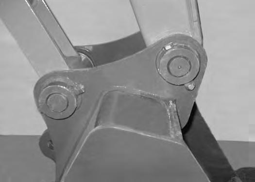
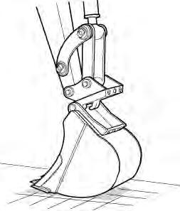
Install the two retainer bolts (Item 1) and jam nuts (Item 2) [Figure78] and tighten the jam nuts.
NOTE:The two retaining bolts (Item 1) [Figure78] should rotate after the two jam nuts are installed. Install the first jam nut until the bolt is finger loose on the mount. Install the second jam nut and tighten the second jam nut against the first jam nut.
Removal
Park the excavator on a flat surface and lower the attachment fully.
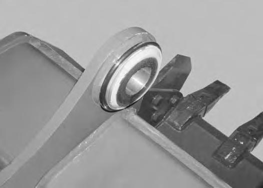
Position the four O-rings (Item 1) [Figure79] into the storage groove of the attachment so they do not get damaged during removal.
Remove the retainer bolts (Item 1) and nuts (Item 2) [Figure78]
Remove the pins (Item 1 and 3) [Figure77]
Warning
Avoid Injury Or Death
Never use attachments or buckets which are not approved by Bobcat Company. Buckets and attachments for safe loads of specified densities are approved for each model. Unapproved attachments can cause injury or death.
W-2052-0907
Reposition the four O-rings (Item 1) [Figure79] next to the arm.
Install grease in the grease fittings on the arm and bucket link pins.
Always use a good quality lithium based multipurpose grease when lubricating the machine. Apply the lubricant until extra grease shows.
ATTACHMENTS (CONT’D)
Installing And Removing The Attachment Quick Coupler, Lehnhoff® System)
Installation
NOTE: Installation and removal of the bucket is shown. The procedure is the same for other attachments. Disconnect any hydraulic lines that are operated by hydraulic power before removing any attachments (breaker, auger etc.).
Warning
AVOID INJURY OR DEATH
Never use attachments or buckets which are not approved by Bobcat Company. Buckets and attachments for safe loads of specified densities are approved for each model. Unapproved attachments can cause injury or death.
W-2052-0907
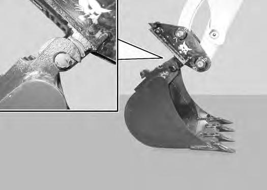
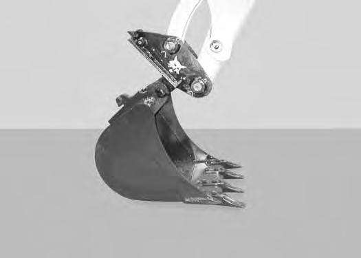
Position the excavator so the excavator arm is above the attachment.
Fully retract the bucket cylinder.
Lower the coupler (Item 1) onto the attachment (Item 2) [Figure80].
Engage the coupler hooks (Item 1) onto the attachment shaft (Item 2) [Figure81]
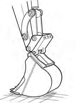
Extend (curl in) the bucket cylinder and slightly raise the boom until the coupler (Item 1) contacts the back of the attachment mount (Item 2) [Figure82].
ATTACHMENTS (CONT’D)
Installing And Removing The Attachment Quick Coupler, Lehnhoff® System) (Cont’d)
Installation (Cont’d)
Figure83
Engage the parking brake.
Stop the engine and exit the excavator.
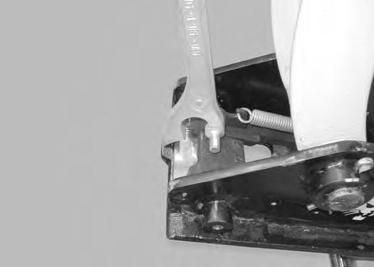
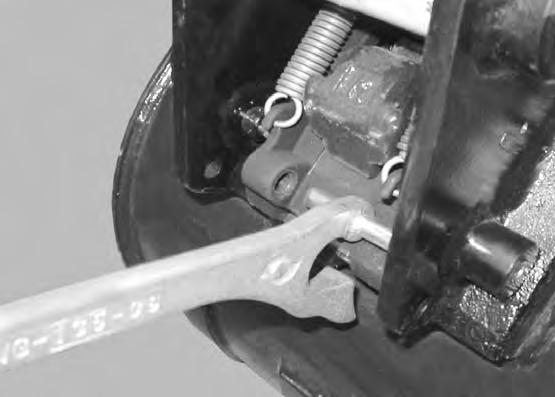
Use the supplied wrench (Item 1) [Figure83] and turn the locking pins clockwise until they are fully engaged.

Removal
Park the excavator on a level surface.
Figure84
S3017A
Install the wrench (Item 1) [Figure85] on the locking pins and turn counter clockwise until the locking pins are disengaged.
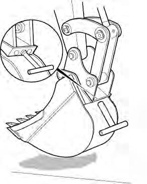
Figure86
S3019A S3020A
Raise the boom and extend the bucket cylinder until the attachment it is slightly off the ground [Figure84]
Engage the parking brake.
Stop the engine and exit the excavator.
Enter the excavator, fasten the seat belt and start the engine
ATTACHMENTS (CONT’D)
Installing And Removing The Attachment (Quick Coupler, Lehnhoff® System) (Cont’d)
Removal (Cont’d)
Figure87
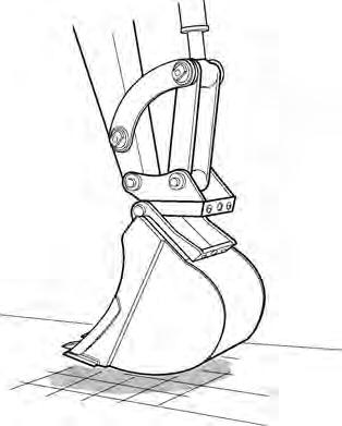
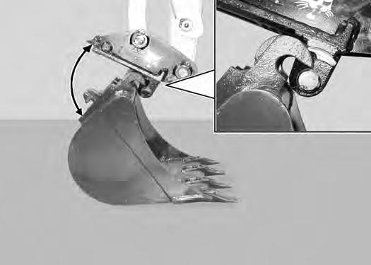
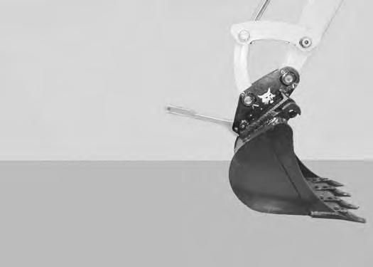
Retract the bucket cylinder to rotate the coupler (Item 1) out of the attachment mount (Item 2) [Figure87]
Quick Coupler And Attachment Inspection
Inspect the quick coupler for wear or damage. Inspect the attachment shaft and the quick coupler hooks for wear or damage.
Repair or replace damaged parts.
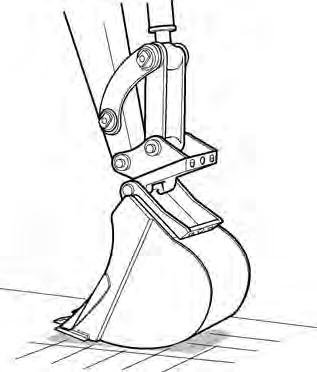
Move the arm out and raise the boom until the quick coupler is clear of the attachment [Figure88]
ATTACHMENTS (CONT’D)

Installing And Removing The Attachment (Quick Coupler, Klack™ System)
Installation
NOTE: Installation and removal of the bucket is shown. The procedure is the same for other attachments. Disconnect any hydraulic lines that are operated by hydraulic power before removing any attachments (breaker, auger etc.).
Warning
AVOID INJURY OR DEATH
Never use attachments or buckets which are not approved by Bobcat Company. Buckets and attachments for safe loads of specified densities are approved for each model. Unapproved attachments can cause injury or death.
W-2052-0907
Warning
AVOID INJURY
Keep fingers and hands out of pinch points when latching and unlatching the attachment quick coupler.
W-2541-1106
Fully retract the bucket cylinder.
Stop the engine and exit the excavator.
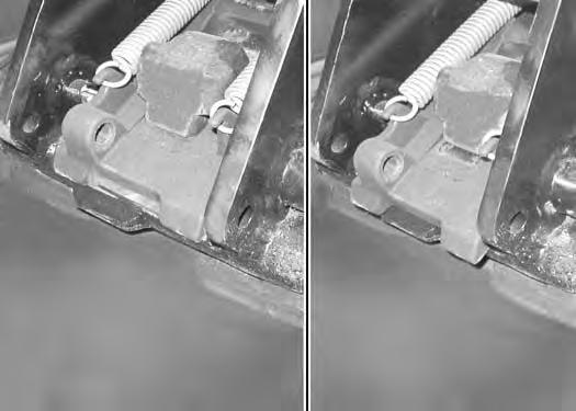
Inspect the quick coupler to make sure the latch is in the unlatched position (Item 1) [Figure89]
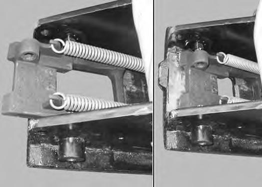
If in the latched position, see [Figure90] for additional information.
If the latch is in the unlatched position, proceed to [Figure91]
To unlatch the quick coupler, install the tool (Item 1) [Figure90] and pull the handle. The latch will move completely forward. The latch will lock in the unlatched position.
Enter the excavator, fasten the seat belt and start the engine.
Position the quick coupler (Item 1) to the attachment (Item 2) [Figure91]
ATTACHMENTS (CONT’D)

Installing And Removing The Attachment (Quick Coupler, Klack™ System) (Cont’d)
Installation (Cont’d)
Figure92
There must be at least 100° between the quick coupler surface (Item 1) and the attachment mounting surface (Item 2) [Figure92]. Extend the arm out to get the required angle for proper installation.

NOTE: There must be proper clearance (100° minimum) between the hook (Item 3) and the quick coupler (Item 4) [Figure92]. Possible damage to the attachment hooks or the quick coupler could occur without proper clearance.
Raise the boom until there is approximately 500 mm (20.0 in) of clearance between the bottom of the attachment and the ground [Figure94]
Raise the boom and extend the arm until the hooks of the attachment (Item 1) engage the pins (Item 2) of the quick coupler [Figure93]
Extend the bucket cylinder (Item 1) [Figure95] fully.
Lower the attachment until it is flat on the ground.
Engage the parking brake.
Stop the engine and exit the excavator.
ATTACHMENTS (CONT’D)
Installing And Removing The Attachment (Quick Coupler, Klack™ System) (Cont’d)
Installation (Cont’d)
Figure96
Visually inspect the quick coupler latch (Item 1) to the bucket mount (Item 2) [Figure96]. The latch must be fully engaged.
Warning
AVOID INJURY
Keep fingers and hands out of pinch points when latching and unlatching the attachment quick coupler.
W-2541-1106
If the latch is not engaged, install the tool (Item 1) in the hole (Item 2) [Figure97] of the quick coupler and push down to unlatch the quick coupler. Remove the tool. Enter the excavator, fasten the seat belt and start the engine. Raise the attachment 500 mm (20.0 in) off of the ground and fully extend the bucket cylinder. Lower the attachment until it is flat on the ground. Engage the parking brake. Stop the engine and exit the excavator.
Again, visually inspect the quick coupler to make sure the latch (Item 1) [Figure96] is fully engaged. If it is not fully engaged, remove the attachment and inspect both the quick coupler and the attachment for damage or debris. (See [Figure101] for Quick Coupler And Attachment Inspection information.)
ATTACHMENTS (CONT’D)
Installing And Removing The Attachment (Quick Coupler, Klack™ System) (Cont’d)
Removal
Warning
AVOID INJURY
Keep fingers and hands out of pinch points when latching and unlatching the attachment quick coupler.
W-2541-1106
Retract the bucket cylinder fully and lower the boom [Figure99] until the attachment is on the ground.
Position the attachment flat on the ground.
Install the quick coupler tool (Item 1) into the hole (Item 2) [Figure97] in the quick coupler.
Push down on the tool (Item 1) [Figure98] to unlock the latch.
Remove the tool.
Enter the excavator, fasten the seat belt and start the engine.
Continue to lower the boom and move the arm towards the excavator until the quick coupler is clear of the attachment [Figure100].
ATTACHMENTS (CONT’D)
Installing And Removing The Attachment (Quick Coupler, Klack™ System) (Cont’d)
Quick Coupler And Attachment Inspection
Figure101
P-72274
Inspect the quick coupler for wear or damage. Inspect the quick coupler pins (Item 1) and the hooks (Item 2) [Figure101] (on the attachment) for wear or damage.
Repair or replace damaged parts.
OPERATING PROCEDURE Inspect The Work Area
Before beginning operation, inspect the work area for unsafe conditions.
Look for sharp drop-offs or rough terrain. Have underground utility lines (gas, water, sewer, irrigation, etc.) located and marked. Work slowly in areas of underground utilities.
Remove objects or other construction material that could damage the excavator or cause personal injury.
Always check ground conditions before starting your work:
•Inspect for signs of instability such as cracks or settlement.
•Be aware of weather conditions that can affect ground stability.
•Check for adequate traction if working on a slope.
Basic Operating Instructions
When operating on a public road or motorway, always follow local bylaws. For example: A slow moving vehicle (SMV) sign, or direction signals may be required.
Run the engine at low idle speed to warm the engine and hydraulic system before operating the excavator.
Important
Machines warmed up with moderate engine speed and light load have longer life.
I-2015-0284
New operators must operate the excavator in an open area without bystanders. Operate the controls until the excavator can be handled at an efficient and safe rate for all conditions of the work area.
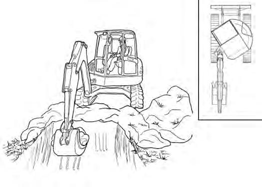
Operating Near An Edge Or Water
Keep the excavator as far back from the edge as possible and the excavator tracks perpendicular to the edge so that if part of the edge collapses, the excavator can be moved back.
Always move the excavator back at any indication the edge may be unstable.
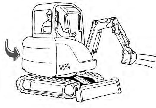
Lowering The Work Equipment (Engine STOPPED)
The hydraulic control levers control the movement of the boom, arm, bucket and upperstructure slew functions.
The console must be in the locked down position and the key switch in the ON position.
Use the control lever (joystick) to lower the boom.
Figure102
The console lock switch disengages the hydraulic control functions from the joysticks when the console is raised [Figure102]
NOTE: If the engine stops, the boom / bucket (attachments) can be lowered to the ground using hydraulic pressure in the accumulator.
The control console must be in the locked down position, and the key switch in the ON position.
Use the control lever (joystick) to lower the boom.
Lower the control console lock lever to engage the hydraulic control functions of the joysticks [Figure102]
OPERATING PROCEDURE (CONT’D)
Lifting A Load
Do not exceed the Rated Lift Capacity.
Warning
AVOID INJURY OR DEATH
Do not exceed rated lift capacity. Excessive load can cause tipping or loss of control.
W-2374-0500
NOTE:Load Holding Valve may be required for lifting objects. Check the regulations in your area. See your Bobcat dealer for load holding valves for your model excavator.
Extend the bucket cylinder completely and lower the boom to the ground. Stop the engine.
Wrap the chain assembly around the bucket mounting plate.
B-16613
Make sure the load is evenly weighted and centred on the lifting chain, and is secured to prevent the load from shifting [Figure103]
Lift and position the load. Once the load is in position and tension is removed from the lift chain (secondary lift system), remove the secondary lift system.
OPERATING PROCEDURE (CONT’D)
Using The Clamp
Figure104
The optional hydraulic clamp attachment gives the excavator a wider range of use and mobility for debris removal [Figure104]
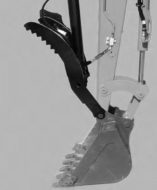
The hydraulic clamp cylinder is operated by the secondary auxiliary hydraulic system (if equipped).
The lifting clamp cylinder must be fully retracted when the machine is being used for excavating.
The lift capacities are reduced by 136 kg (300 lb) if the excavator is equipped with the optional hydraulic clamp.
Warning
Avoid Injury Or Death
Check area to be excavated for overhead or underground lines such as electrical, gas, oil, water, etc. DIAL 811 (USA Only) or 1-888-258-0808 (USA & Canada) and consult local utilities before digging. Extreme caution must be used in areas where utility lines are present.
W-2686-1007
When Using Secondary Auxiliary Hydraulics To Activate Clamp
Figure105
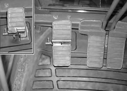
Release the pedal lock (Item 1) and pivot the heel of the pedal to the rear (Item 2) [Figure46].
Push the toe of the pedal (Item 3) to close the clamp; push the heel of the pedal (Item 4) [Figure46] to open the clamp.
OPERATING PROCEDURE (CONT’D)
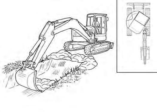
Excavating
Warning
Keep all bystanders 6 m (20 ft) away from equipment when operating. Contact with moving parts, a trench cave-in or flying objects can cause injury or death.
W-2119-0910
Lower the blade for increased digging performance.
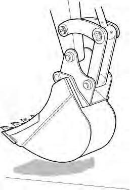
Raise the boom, retract the arm and curl the bucket [Figure108]
Rotate the upperstructure.
NOTE: Do not allow the bucket teeth to contact the ground when swinging the upperstructure.
Warning
AVOID
Injury Or Death
Extend the arm, lower the boom, and open the bucket [Figure106].
Check area to be excavated for overhead or underground electrical power lines. Keep a safe distance from electrical power lines.
W-2757-EN-1009
Retract the arm, while lowering boom and curling the bucket [Figure107]
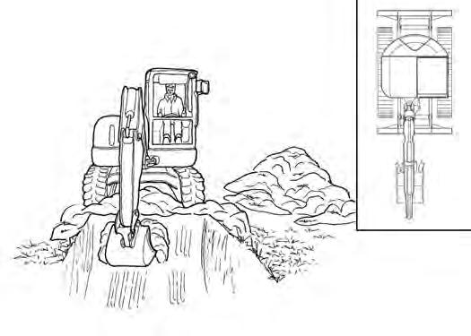
OPERATING PROCEDURE (CONT’D)
Excavating (Cont’d)
Look in the direction of rotation and make sure there are no bystanders in the work area before rotating the upperstructure [Figure109]
Do not dig under the excavator [Figure111]
Do not use the bucket as a breaker or pile driver. It is better to excavate hard or rocky ground after breaking it with other equipment. This will reduce damage to the excavator.
Do not move the excavator while the bucket is in the ground.
Extend the arm and uncurl the bucket to dump the material into a pile or truck [Figure110].
Important
Avoid operating hydraulics over relief pressure. Failure to do so will overheat hydraulic components.
I-2220-0503
OPERATING PROCEDURE (CONT’D)
Boom Swing
Slew the upperstructure, swing the boom to the right [Figure112], centre [Figure113] and left [Figure114] to dig a square hole the width of the machine without repositioning the excavator.
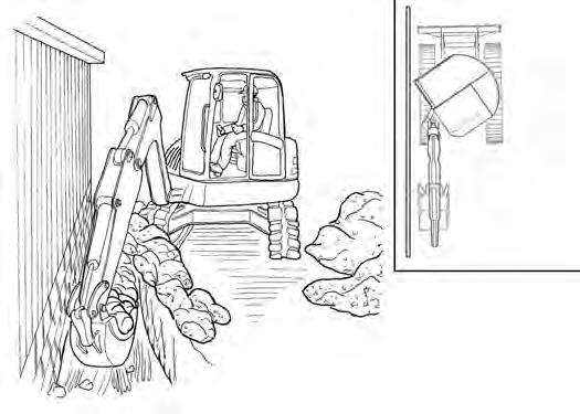
The boom swing allows the operator to offset the boom and dig close to buildings and other structures [Figure115]
OPERATING PROCEDURE (CONT’D)
Backfilling
Important
Avoid impacting objects with the blade. Damage to blade and undercarriage components may occur.
I-2256-0507
Driving The Excavator
When operating on uneven ground, operate as slow as possible and avoid sudden changes in direction.
Avoid traveling over objects such as rocks, trees, stumps, etc.
When working on wet or soft ground, put planks on the ground to provide a solid base to travel on and prevent the excavator from getting stuck.
Use the blade to backfill the trench or hole after excavating [Figure116]
If one or both tracks have become stuck in soft or wet ground, raise one track at a time by turning the upperstructure and pushing the bucket against the ground [Figure117].
Put planks under the tracks and drive the excavator to dry ground.
The bucket may also be used to pull the excavator. Raise the blade, extend the arm and lower the boom. Operate the boom and arm in a digging manner [Figure118]
OPERATING PROCEDURE (CONT’D)
Operating On Slopes
Warning
AVOID INJURY OR DEATH
•Do not travel across or up slopes that are over 15 degrees.
•Do not travel down or back up slopes that exceed 25 degrees.
•Look in the direction of travel.
W-2497-0304
When going down a slope, control the speed with the steering levers and the engine speed control dial.
Traveling Down or Backing Up Slopes
304 mm (12 in) Maximum
When going down grades that exceed 15 degrees, put the machine in the position shown, and run the engine slowly [Figure119].
Operate as slow as possible and avoid sudden changes in lever direction.
Avoid traveling over objects such as rocks, trees, stumps, etc.
Stop the machine before moving the upper equipment controls. Never allow the blade to strike a solid object. Damage to the blade or hydraulic cylinder can result.
Warning
AVOID INJURY OR DEATH
•Avoid steep areas or banks that could break away.
•Keep boom centred and attachments as low as possible when travelling on slopes or in rough conditions. Look in the direction of travel.
•Always fasten seat belt.
W-2498-EN-1009
When traveling up slopes or on side slopes that are 15 degrees or less, position the machine as shown and run the engine slow [Figure120] and [Figure121]