18 minute read
INSTRUMENTS AND CONSOLES (CONT’D)


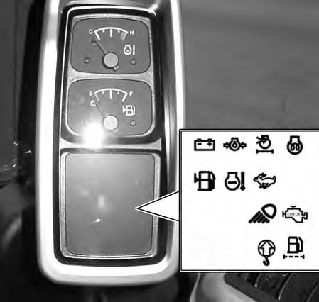
Function Icons
The table below shows the Icons, their function and other important information.
1 System Voltage OFF ON
2 Engine Oil Pressure OFF ON
3 Engine Air Filter OFF ON
DESCRIPTION
WarningVoltage out of range - Light will be ON when key is turned to the ON position with engine not started, light will go OFF after engine starts. If light is ON with engine running, shut engine OFF immediately an determine cause of problem.
WarningOil pressure low - Light will be ON when key is turned to the ON position with engine not started, light will go OFF after engine starts. If light is ON with engine running, shut engine OFF immediately. If engine is operated with light ON, serious engine damage may occur.
WarningIndicates the air filter(s) needs servicing when light is ON.
4 Air Intake Heater OFF ON --- Air intake heater energized. In cold weather with the key in the ON position, the icon indicates the engine preheat feature is activated. When icon is OFF with the key in the ON position means the engine preheat cycle has finished and the engine can be started.
5 Low Fuel OFF ON
6 Engine Coolant Temperature
OFF ON
WarningLight ON when fuel in tank is approximately 10 L (2.6 U.S. gal) or less. Add fuel as soon as possible.
WarningLight ON when engine temperature exceeds allowable limit. Alarm will sound and the engine RPM will automatically be reduced. Check engine temperature gauge, if indicator is in red zone on gauge, allow engine to idle until engine temperature reaches white zone. Continue to allow engine to idle for another few minutes. Stop engine and allow to cool before servicing.
7 Two-Speed Travel OFF ON --- Light ON when Two-Speed activated, High Range engaged.
8 Working Lights OFF ON --- Light ON when working lights ON.
9 Engine Check OFF ON
10 Overload Warning OFF ON
WarningLight flashes when engine needs servicing. Stop engine and service as needed. (Light flashes a service code pattern to indicate problem.)
WarningWhen switch is activated - the light ON and alarm sounding indicates the load exceeds the maximum allowable limit (lift capacity exceeded). Reduce load immediately.
11 Water In Fuel OFF ON -
WarningLight ON when water in fuel filter is indicated. Drain water from fuel filter as soon as possible. P-86955A
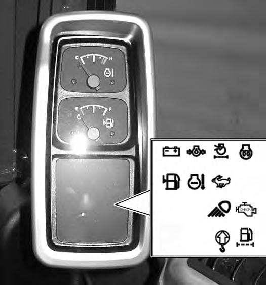
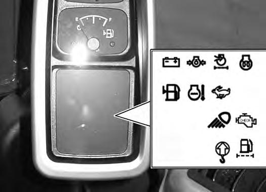
Engine Coolant Temperature Gauge (Item 1) [Figure10] Gauge indicate engine coolant temperature and allowable operating range. WHITE area indicates coolant temperature is in normal operating range. RED area indicates engine coolant temperature is to high. When in RED area, engine rpm will automatically be reduced. Allow engine to idle until engine temperature is in normal operating range. Stop the engine and allow coolant to cool and service as required.
Fuel Level Gauge (item 2) [Figure10]. Shows amount of fuel in fuel tank.
Function Icons (Item 3) [Figure10], see above information.
INSTRUMENTS AND CONSOLES (CONT’D)
Upperstructure Slew Brake
This excavator is equipped with an automatically applied slew brake integrated into the slew motor.
When the upperstructure slew circuit is engaged, hydraulic pressure unlocks the slew motor.
When the upperstructure slew circuit is disengaged, spring pressure applies the internal slew motor brake.
Raising And Lowering The Console
Raise the console before exiting the cab.
Figure11
Pull up on the console release handle (Item 1) [Figure11]
Lower the console before operating the excavator.

Push down on the console release handle (Item 1) [Figure11] until the latch is engaged.
NOTE: When the console is raised, the hydraulic and traction system functions are locked and will not operate.
If the engine stops, the boom / bucket (attachments) can be lowered to the ground using hydraulic pressure in the accumulator.
The control console must be in the locked down position and the key switch in the ON position.
INSTRUMENTS AND CONSOLES (CONT’D)
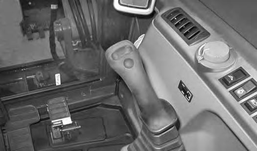
Two-Speed Travel
Figure12
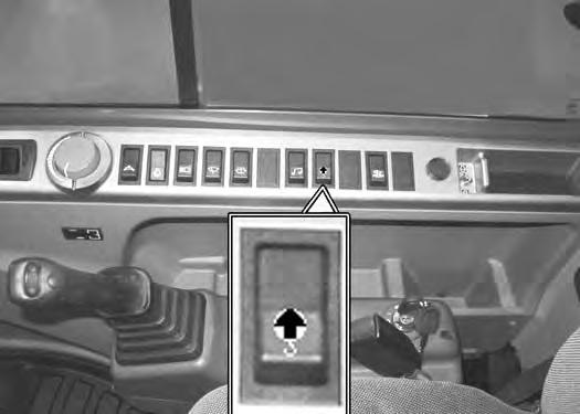
Press the bottom of the two-speed button (Item 1) [Figure12] to engage the High Range.
Figure13
When High Range is engaged, the two-speed travel icon (Item 1) [Figure13] will illuminate.
Press the top of the two-speed button (Item 1) [Figure12] to disengage.
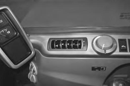
Engine Speed Control Dial
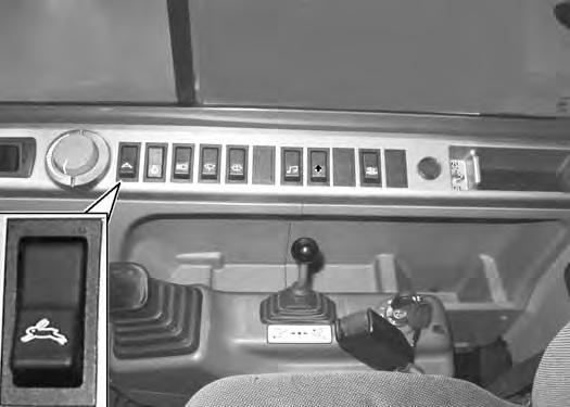
Figure14
The engine speed control dial (Item 1) [Figure14] controls the engine rpm. Rotate the knob clockwise to increase engine rpm, anticlockwise to decrease engine rpm.
Automatic Idle
The auto idle feature (when engaged) will reduce the engine speed to low idle when the control levers (joystick, blade, travel, etc.) are in neutral and not used for approximately four seconds. The engine rpm will return to the set position as soon as any control lever is activated.
The automatic idle switch (Item 2) [Figure14] is used to engage or disengage the automatic idle feature.
Press the bottom of the switch (Item 2) to engage automatic idle, press the top of the switch (Item 2) [Figure14] to disengage automatic idle.
NOTE:When loading or unloading the machine or when operating in confined spaces, disengage the auto idle feature.
OPERATOR CANOPY (ROPS / TOPS)
Description
The Bobcat excavator has an operator canopy (ROPS / TOPS) as standard equipment to protect the operator if the excavator is tipped over. The seat belt must be worn for ROPS / TOPS protection.
Check the ROPS / TOPS canopy, mounting, and hardware for damage. Never modify the ROPS / TOPS canopy. Replace the canopy and hardware if damaged. See your Bobcat dealer for parts.
ROPS / TOPS - Roll Over Protective Structure per ISO 12117-2, and Tip Over Protective Structure per ISO 12117.
Warning
Never modify operator cab by welding, grinding, drilling holes or adding attachments unless instructed to do so by Bobcat Company. Changes to the cab can cause loss of operator protection from rollover and falling objects, and result in injury or death.
W-2069-0200
OPERATOR CAB (ROPS / TOPS)
Description
The Bobcat excavator has an optional operator cab (ROPS / TOPS) as standard equipment to protect the operator if the excavator is tipped over. The seat belt must be worn for ROPS / TOPS protection.
Check the ROPS / TOPS cab, mounting, and hardware for damage. Never modify the ROPS / TOPS cab. Replace the cab and hardware if damaged. See your Bobcat dealer for parts.
ROPS / TOPS - Roll Over Protective Structure per ISO 12117-2, and Tip Over Protective Structure per ISO 12117.
Warning
Never modify operator cab by welding, grinding, drilling holes or adding attachments unless instructed to do so by Bobcat Company. Changes to the cab can cause loss of operator protection from rollover and falling objects, and result in injury or death.
W-2069-0200
OPERATOR CAB (ROPS / TOPS) (CONT’D)
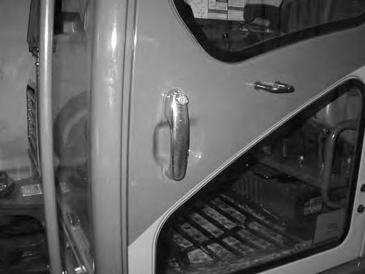
Cab Door
The cab door can be locked (Item 1) [Figure15] with the same key as the start switch.
The door can be held in the open position. Push the door all the way open until the latch (Item 2) [Figure15] engages to hold the door in the open position.
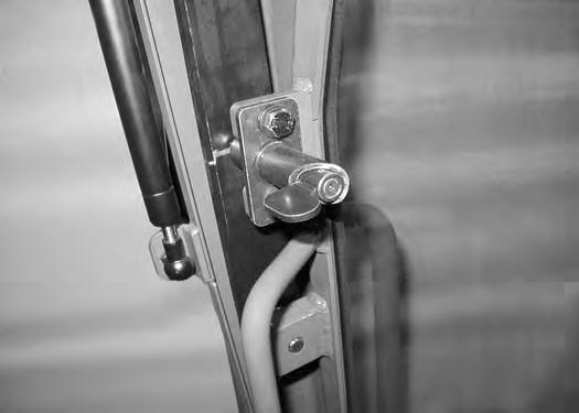
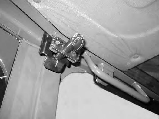
When the door is in the open position, push down on the latch (Item 1) [Figure16] and close the door.
From inside the cab, open the door using handle (Item 2) [Figure16]

OPERATOR CAB (ROPS / TOPS) (CONT’D)
Front Window
Opening The Front Window
Figure17
Rotate the front window latch pins (Item 1) [Figure17] (both sides).
When the window is fully raised, push up on the window slightly until the two latch pins (Item 1) (both sides) engage into the bracket (Item 2) [Figure19] to lock the window in the open position. Pull down slightly on the window to make sure the latch pins are properly seated to hold the window securely in the open position.
Closing The Front Window
Support the window while rotating both window latch pins (Item 1) [Figure19] to the unlocked position.
Using both window grab handles, pull the window forward and down to the closed position [Figure18]
When the window is fully lowered, push in on the window slightly until the two latch pins (Item 1) [Figure17] (both sides) engage into the bracket to lock the window in the closed position.
Use both window grab handles to pull the top of the window in [Figure18].
Continue moving the window in and up over the operator’s head until the window is fully raised.

OPERATOR CAB (ROPS / TOPS) (CONT’D)
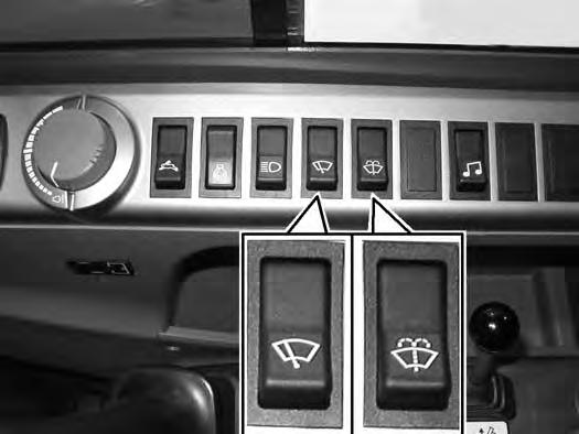
Front Wiper
The front window is equipped with a wiper (Item 1) [Figure20] and washer.
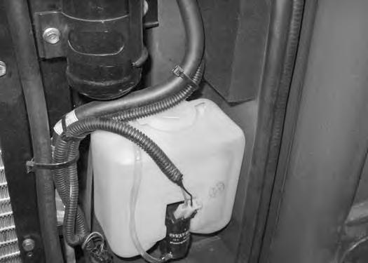
Window Washer Reservoir
Figure22
The wiper switch (Item 1) [Figure21] has three positions, OFF, intermittent wiper mode and full speed.
The window washer switch (Item 2) activates the front window washer. (The wiper switch (Item 1) must be activated before the washer switch (Item 2) [Figure21] will allow washer fluid to be sprayed on the front window.)

The window washer reservoir (Item 1) [Figure22] is located under the right side cover and to the front of the radiator. (When the temperature is 0°C (32°F) or lower, fill the washer reservoir with washer fluid specified for freezing conditions. If the washer bottle is filled with water, it will freeze and damage the washer reservoir.)
OPERATOR CAB (ROPS / TOPS) (CONT’D)
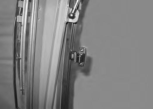
Right Side Window
Opening The Right Front Window
Figure23
Press the latch / handle (Item 1) [Figure23] together and pull back on the latch / handle to open the right side window.
Closing The Right Front Window
Push the latch / handle (Item 1) [Figure23] forward until the latch / handle lock the window in the closed position.
OPERATOR CAB (ROPS / TOPS) (CONT’D)
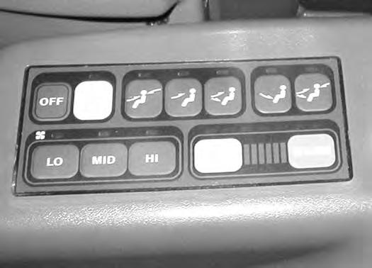

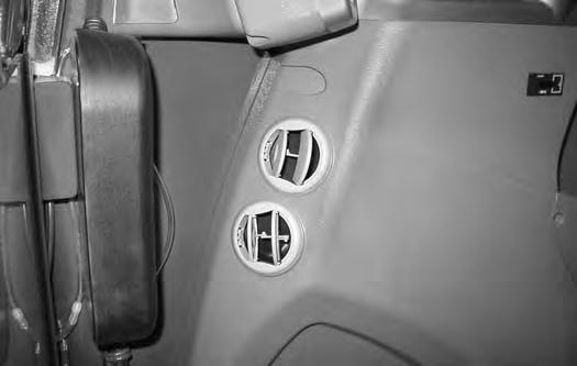
Heating, Ventilation And Air Conditioning Duct
TRAVEL CONTROLS Description
The travel control levers control the movement of the excavator.
Forward And Reverse Travel
NOTE: The following procedures describe forward, reverse, left and right as seated in the operator’s seat.
Figure28
Put the blade so that it is at the front of the machine (as you sit in the operator’s seat). Slowly move both steering levers* (Item 1) [Figure28] forward for forward travel; backward for reverse travel.

* Travel can also be controlled with foot pedals (Item 2) [Figure28]
Warning
AVOID INJURY OR DEATH
•Check the blade location before travelling. When the blade is to the rear, operate the steering levers/foot pedals in the opposite direction to when the blade is in the front.
•Move the steering levers/foot pedals slowly. Abrupt lever motion will cause the machine to jerk.
W-2235-EN-1009
Turning Right Turn
Figure29
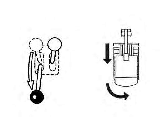
Push the left steering lever forward to turn right [Figure29] while traveling forward.
Pull the left steering lever backward to turn right while traveling backward [Figure30]
TRAVEL CONTROLS (CONT’D)
Turning (Cont’d)
Counter - Rotation Right Turn
Counter - Rotation Right Turn
Left Turn (Reverse)
B-19990
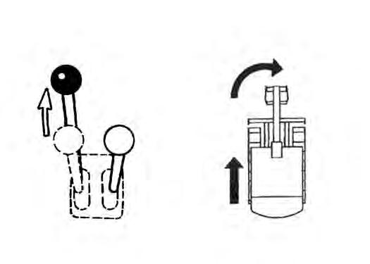
Pull the right steering lever backward to turn left while traveling backward [Figure33]
Counter - Rotation Left Turn
B-19988
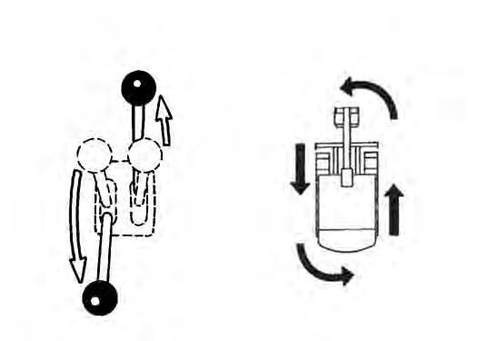
Push the left steering lever forward and pull the right steering lever backward [Figure31]
Left Turn
Left Turn (Forward)
B-19989
Push the right steering lever forward to turn left [Figure32] while traveling forward.
Counter - Rotation Left Turn
B-19991
Push the right steering lever forward and pull the left steering lever backward [Figure34]
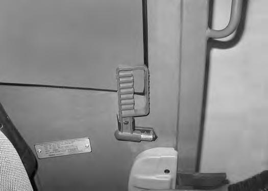
Emergency Exits
The door, the right side rear window and the front window provide emergency exits.
Right Rear Side Window
Figure35
If emergency exit requires breaking a window, use the supplied hammer (Item 1) [Figure35] located on the left side of the operator cab.

Front Window
Figure38
Remove the hammer from the storage position and strike the glass with the pointed end of the hammer [Figure36]
Use the hammer to remove broken glass from the edge of the window before exiting.

Open the front window and exit [Figure38]
NOTE:If the excavator has a FOGS Kit installed, the front window is NOT an emergency exit.
MOTION ALARM SYSTEM Operation
Warning
This machine is equipped with a motion alarm. ALARM MUST SOUND! when operating forward or backward.
Failure to maintain a clear view in the direction of travel could result in serious injury or death.
The operator is responsible for the safe operation of this machine.
W-2786-0309

With the switch (Item 1) [Figure40] in the ON position, the motion alarm will sound when the operator moves the travel control levers in the either the forward or reverse direction.
If alarm does not sound (with the switch (Item 1) [Figure40] in the ON position) or for adjustment instructions, see inspection and maintenance instructions for the motion alarm system in the preventive maintenance section of this manual. (See MOTION ALARM SYSTEM on Page 98.)

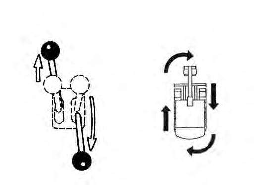
HYDRAULIC CONTROLS Description
The work equipment (boom, arm, bucket, and upperstructure slew) is operated by using the left and right control levers (joysticks).
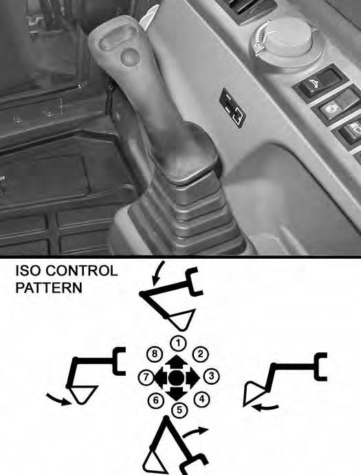
ISO Control Pattern
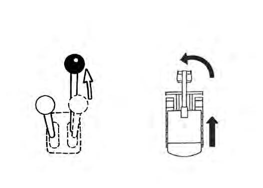
Left Control Lever (Joystick)
Figure41
The left lever (joystick) is used to operate the arm and slew the upperstructure [Figure41].
1.Arm out.
2.Arm out and slew right.
3.Slew right.
4.Arm in and slew right.
5.Arm in.
6.Arm in and slew left.
7.Slew left.
8.Arm out and slew left.
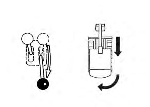
Right Control Lever (Joystick)
Figure42
The right lever (joystick) is used to operate the boom and bucket [Figure42]
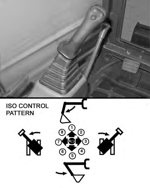
1.Boom lower.
2.Boom lower and bucket dump.
3.Bucket dump.
4.Boom raise and bucket dump.
5.Boom raise.
6.Boom raise and bucket curl.
7.Bucket curl.
8.Boom lower and bucket curl.
Warning
AVOID INJURY OR DEATH
Before leaving the machine:
•Lower the work equipment to the ground.
•Lower the blade to the ground.
•Stop the engine & remove the key.
W-2196-0595
HYDRAULIC CONTROLS (CONT’D)
Quick Couplers
Warning
Avoid Burns
Hydraulic fluid, tubes, fittings and quick couplers can get hot when running machine and attachments. Be careful when connecting and disconnecting quick couplers.
W-2220-0396
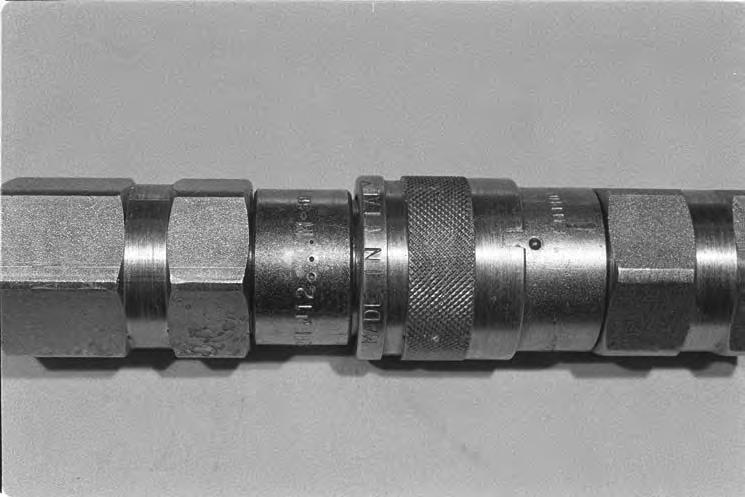
To Disconnect:
Figure44
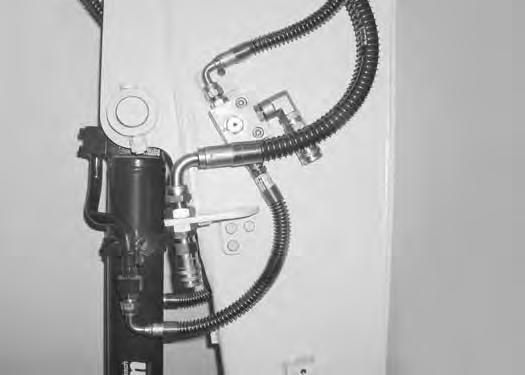
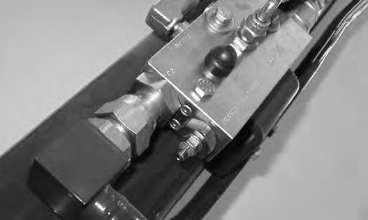
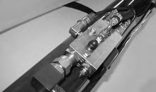
Excavator and attachments use flush faced couplers (Item 1 and 2) [Figure43]. The male flush face couplers are located on the right side of the arm (shown), the female coupler is located on the left side of the arm.
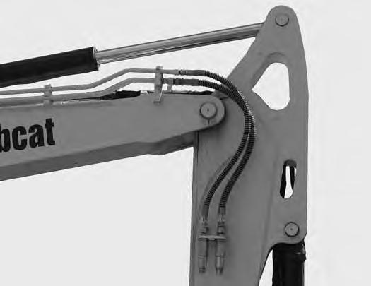
Coupler (Item 1) is for one way flow auxiliary hydraulics, coupler (Item 2) [Figure43] is the secondary auxiliary hydraulics.
To Connect:
Remove any dirt or debris from the surface of both the male and female couplers, and from the outside diameter of the male coupler. Visually check the couplers for corroding, cracking, damage, or excessive wear, if any of these conditions exist, the coupler(s) (Item 1) [Figure43] must be replaced.
Install the male coupler into the female coupler. Full connection is made when the ball release sleeve slides forward on the female coupler.
Hold the male coupler (Item 1). Retract the sleeve (Item 2) [Figure44] on the female coupler until the couplers disconnect.
HYDRAULIC CONTROLS (CONT’D)

Auxiliary Hydraulics (One Way Flow)
Figure45
Press and hold the Auxiliary Hydraulics button (Item 1) [Figure45] on the right joystick to supply hydraulic flow / pressure to the female coupler.
NOTE: The auxiliary hydraulic switch (Item 1) [Figure45] is for one way flow to the female coupler, return flow through the male coupler only. If two way flow auxiliaries are required for an attachment, the secondary auxiliary hydraulic function kit will need to be used. (See Below)
Auxiliary Hydraulics (Secondary Auxiliaries) (If Equipped)
Auxiliary Hydraulics (Third Auxiliaries) (If Equipped)
Figure47
Release the pedal lock (Item 1) and pivot the heel of the pedal to the rear (Item 2) [Figure46]
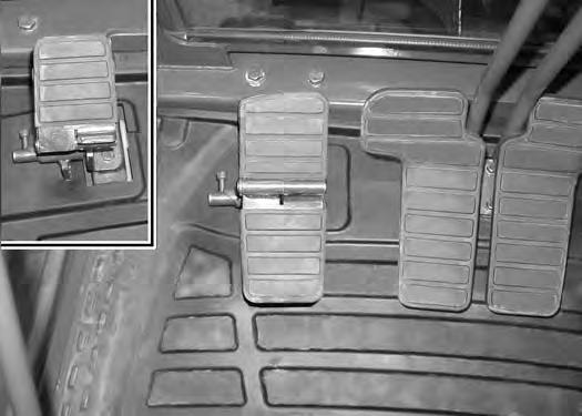
Push the toe of the pedal (Item 3) to supply hydraulic flow and pressure to the female coupler; push the heel of the pedal (Item 4) [Figure46] to supply hydraulic flow and pressure to the male coupler.
NOTE: For breaker applications, use the one way auxiliary hydraulic switch (Item 1) [Figure45].
Rotate the valve (Item 1) 1/4 turn clockwise (both sides) for the third auxiliary coupler (Item 2) function. Rotate the valve (Item 1) [Figure47] (both sides) 1/4 turn anticlockwise for the bucket function.
NOTE:The bucket function is not usable when the third auxiliary hydraulics are activated.
Use the right joystick (Item 1) [Figure48] (same as the bucket function). Move the joystick to the left for hydraulic flow to the female coupler. Move the joystick to the right for hydraulic flow to the male coupler.
NOTE: For breaker applications, use the one way auxiliary hydraulic switch (Item 1) [Figure45].
HYDRAULIC CONTROLS (CONT’D)
Relieve Hydraulic Pressure - One Way Flow (Excavator And Attachment)
Excavator:
Put the attachment flat on the ground.
Stop the engine and turn the key to ON.
NOTE: The left console must be fully lowered for relieving hydraulic pressure.
Press the switch (Item 1) [Figure45] several times.
Attachments:
•Follow procedure above to release pressure in excavator.
•Connect male coupler from attachment to female coupler of excavator then repeat procedure above. This will release pressure in the attachment.
•Connect the female coupler from the attachment.
Hydraulic pressure in the auxiliary hydraulic system can make it difficult to engage quick couplers to an attachment.
Relieve Hydraulic Pressure - Third Auxiliaries (If Equipped) (Excavator And Attachment)
Excavator:
Put the attachment flat on the ground.
NOTE: The valves (Item 1) [Figure47] must be rotated to the third auxiliary position before hydraulic pressure can be relieved.
Stop the engine and turn the key to ON.
NOTE: The left console must be fully lowered for relieving hydraulic pressure.
Move the right joystick (Item 1) [Figure48] left and right several times.
Attachments:
•Follow procedure above to release pressure in excavator.
•Connect male coupler from attachment to female coupler of excavator then repeat procedure above. This will release pressure in the attachment.
•Connect the female coupler from the attachment.
Hydraulic pressure in the auxiliary hydraulic system can make it difficult to engage quick couplers to an attachment.
Relieve Hydraulic Pressure - Secondary Auxiliaries (If Equipped) (Excavator And Attachment)
Excavator:
Put the attachment flat on the ground.
Stop the engine and turn the key to ON.
NOTE: The left console must be fully lowered for relieving hydraulic pressure.
Press the auxiliary hydraulic pedal forward (Item 3) and back (Item 4) [Figure46] several times.
Attachments:
•Follow procedure above to release pressure in excavator.
•Connect male coupler from attachment to female coupler of excavator then repeat procedure above. This will release pressure in the attachment.
•Connect the female coupler from the attachment.
Hydraulic pressure in the auxiliary hydraulic system can make it difficult to engage quick couplers to an attachment.
BLADE CONTROL LEVER Operation
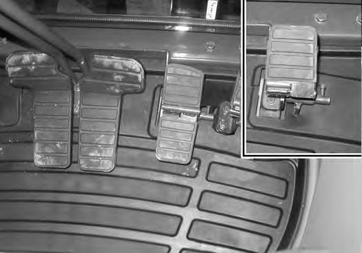
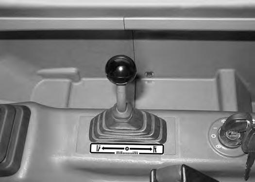
Figure49
Pull the lever backward to raise the blade (Item 1) [Figure49]
Push the lever forward to lower the blade (Item 2) [Figure49]
NOTE: Keep the blade lowered for increased digging performance.
BOOM SWING PEDAL Operation
Figure50
Release the pedal lock (Item 1) and pivot the heel of the pedal to the rear (Item 2) [Figure50]
Push the toe of the pedal (Item 3) to swing the boom to the right; push the heel of the pedal (Item 4) [Figure50] to swing the boom to the left.
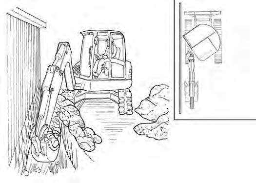
Figure51
NOTE: The purpose of the boom swing pedal is to offset the boom with respect to the upperstructure for digging close to a structure [Figure51].
OVERLOAD WARNING Description
The overload warning feature, when engaged, will alert the operator with a warning buzzer and overload icon on the instrument panel when the work group is overloaded. If overload occurs, immediately bring the arm towards the machine, lower the boom and reduce the load before continuing operation.
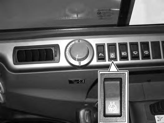
To engage the overload warning feature, press the switch (Item 1) [Figure52]. The switch icon will be illuminated when engaged.
If overload occurs, immediately bring the arm towards the machine, lower the boom and reduce the load before continuing operation.
Do not exceed the Rated Lift Capacity.
AVOID INJURY OR DEATH
Do not exceed rated lift capacity. Excessive load can cause tipping or loss of control.
BOOM LOAD HOLDING VALVE Description
The boom load holding valve will hold the boom in it’s current position in the event of hydraulic pressure loss.
Warning
AVOID INJURY OR DEATH
Do Not work or stand under raised work equipment or attachment.
W-2793-0409
Lowering Boom With Load Holding Valve
NOTE:The boom load holding valve is required for object handling applications.
Lowering procedures:
NOTE:Mark the position of the set screw so that it can be returned to the original location after the boom has been lowered.
With base end hose failure:
Loosen the jam nut (Item 1). Install a hex wrench into the valve screw (Item 2) [Figure55] and slowly rotate the screw clockwise and allow the boom to lower to the ground. (The more the screw is rotated, the faster the boom will lower.)
After the boom is fully lowered, rotate the screw (Item 2) counter clockwise (back to the original position) and tighten the lock nut (Item 1) [Figure55]
With rod end hose failure - with accumulator pressure:
The boom load holding valve (Item 1) [Figure54] is attached to the boom cylinder at the base end.
NOTE:DO NOT remove or adjust the port relief valve (Item 2) [Figure54]. If the port relief valve has been tampered with, see your Bobcat dealer.
Warning
AVOID BURNS
Hydraulic fluid, tubes, fittings and quick couplers can get hot when running machine and attachments. Be careful when connecting and disconnecting quick couplers.
W-2220-0396
Place a container under the valve and the hose end to contain hydraulic fluid. Enter the excavator and turn the key to the ON position but do not start the engine. Slowly move the joystick boom lower function and allow the boom to lower to the ground.
With rod end hose failure - with NO accumulator pressure:
Remove the boom base end hose from the boom load holding valve. Place a container under the valve and the base end hose to contain the hydraulic fluid.
Loosen the jam nut (Item 1). Install a hex wrench into the valve screw (Item 2) [Figure55] and slowly rotate the screw clockwise and allow the boom to lower to the ground. (The more the screw is rotated, the faster the boom will lower.)
After the boom is fully lowered, rotate the screw (Item 2) counter clockwise (back to the original position) and tighten the lock nut (Item 1) [Figure55]
Loss of hydraulic pressure:
Use the same procedure as: With rod end hose failure and NO accumulator pressure.
DAILY INSPECTION (CONT’D)
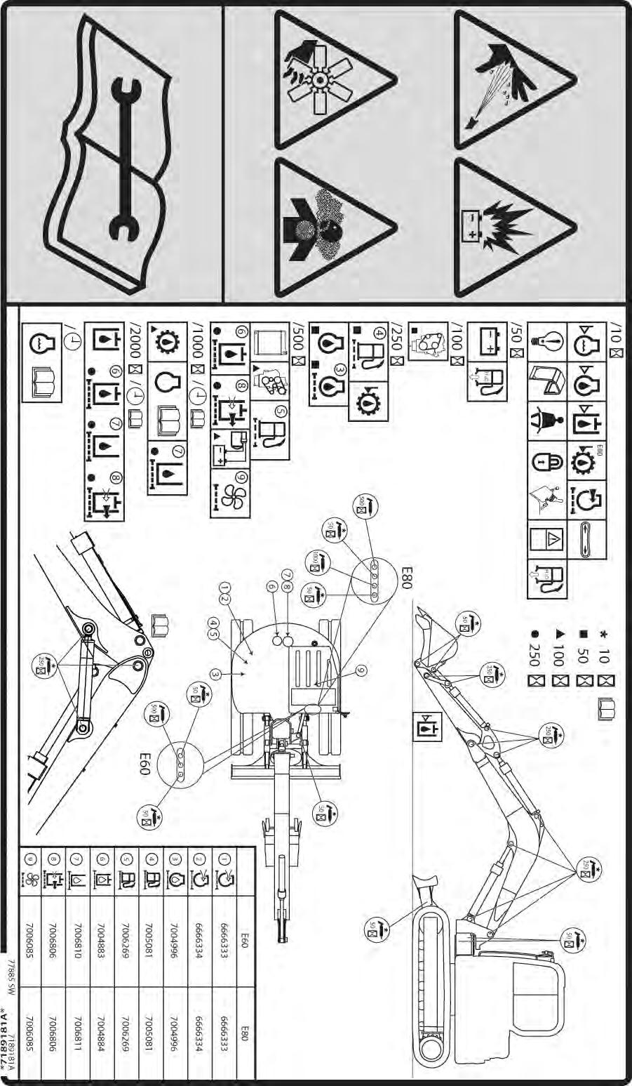
Daily Inspection And Maintenance
Maintenance work must be done at regular intervals. Failure to do so will result in excessive wear and early failures. The Service Schedule [Figure 56] is a guide for correct maintenance of the Bobcat excavator. It is located on the right front corner of the excavator upperstructure and also in this manual.
Check the following items before each day of operation:
•Operator Cab (ROPS / TOPS) and mounting hardware.
•Seat belt and mounting hardware. Replace seat belt if damaged.
•Check for damaged decals, replace as needed.
•Check control console lockout.
•Check X-Change System (if equipped) for damage or loose parts.
•Air cleaner condition indicator and intake hoses/ clamps.
•Engine oil level and engine for leaks.
•Engine coolant level and engine for leaks.
•Check engine area for flammable materials.
•Check hydraulic fluid level and system for leaks.
•Check indicator lights for correct operation.
•Drain water and sediment from fuel tank and filter.
•Check cylinder and attachment pivot points.
•Check the track tension.
•Repair broken and loose parts.
•Clean cab heater filter (if equipped).
•Check front horn and motion alarm (if equipped) for proper function.
Warning
Operator must have instructions before operating the machine. Untrained operators can cause injury or death.
W-2001-0502
Fluids such as engine oil, hydraulic fluid, coolants, etc. must be disposed of in an environmentally safe manner. Some bylaws require that certain spills and leaks on the ground must be cleaned in a specific manner. See local bylaws for correct disposal.
Important
Pressure Washing Decals
•Never direct the stream at a low angle toward the decal that could damage the decal causing it to peel from the surface.
•Direct the stream at a 90 degree angle and at least 300 mm (12 in) from the decal. Wash from the centre of the decal toward the edges.
I-2226-EN-0910
Important
This machine is factory equipped with a spark arrester exhaust system.
The spark arrester muffler, if equipped, must be cleaned to keep it in working condition. The spark arrester muffler must be serviced by dumping the spark chamber every 100 hours of operation.
On some models, the turbocharger functions as the spark arrester and must operate correctly for proper spark arrester function.
If this machine is operated on flammable forest, brush, or grass covered land, a spark arrester attached to the exhaust system may be required and must be maintained in working order. Refer to local laws and regulations for spark arrester requirements.
I-2284-EN-0909
PRE-STARTING PROCEDURE
Operation & Maintenance Manual And Operator’s Handbook Locations
Entering The Excavator
Warning
AVOID INJURY OR DEATH
Read and understand the Operation & Maintenance Manual (Item 1) [Figure57] (located inside the storage box on the back of the operator’s seat) and the Operator’s Handbook (Item 1) [Figure58] before operating.
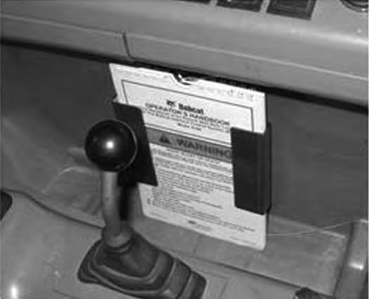

Instructions are necessary before operating or servicing machine. Read and understand the Operation & Maintenance Manual, Operator’s Handbook and signs (decals) on machine. Follow warnings and instructions in the manuals when making repairs, adjustments or servicing. Check for correct function after adjustments, repairs or service. Untrained operators and failure to follow instructions can cause injury or death.

PRE-STARTING PROCEDURE (CONT’D)
Seat Adjustment
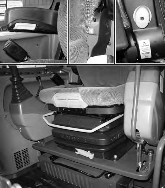
Figure60
Release the seat lever (Item 1) [Figure60] to adjust the seat forward or backward.
Turn the handle (Item 2) to change the adjustment for operator weight. Turn the handle until the operator’s weight is shown in the window (Item 3) [Figure60]
Release the lever (Item 4) [Figure60] (on the back of the seat) to change the lumbar support.
Rotate the knob (Item 5) [Figure60] (on the lower left side of the seat) to change the incline of the seat back.
Rotate the knob (Item 6) [Figure60] (on both arm rest) to change the angle of the arm rest.
Release the lever (Item 7) [Figure60] to change the position of the lower cushion forward or back.
Release the lever (Item 8) [Figure60] to change the angle of the lower cushion.
The operator’s group (seat and left and right consoles) can be adjusted forward or backward. Adjust the operator’s group using the lever (Item 9) [Figure60]
To adjust seat height, sit in the seat and fasten the seat belt. Place your hands to the sides of the cab (not on the consoles) and lift up slowly with your arms and legs, raising the seat. The seat has four adjustment positions. When the top position is reached, the seat will reset and allow the seat to go back to the lowest position.

Heated Seat (If Equipped). The optional heated seat has a switch (Item 11) [Figure61] located on the left side of the seat. Press the top of the switch to activate the heated seat. Press the bottom of the switch to turn off.
Seat Belt Adjustment
Figure62
Fasten the seat belt (Item 1) [Figure62]
Press the red button (Item 2) [Figure62] to release the seat belt.