2 minute read
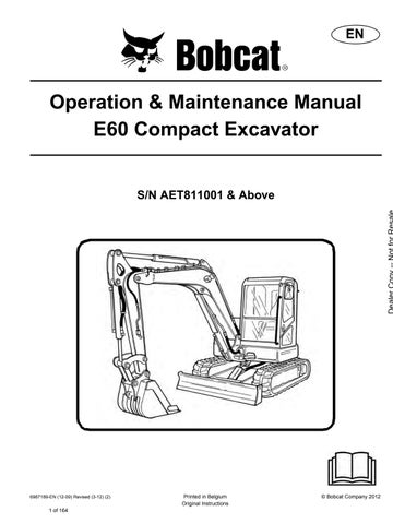
INSTRUMENT PANEL IDENTIFICATION


1 Left Joystick(See HYDRAULIC CONTROLS on Page 50.)
2 Horn Press lower button on left joystick to sound horn. (Key switch must be in ON position for horn to operate.) (The top two switches on the left joystick are not used for this model.)
3 Air Conditioner / Fan Motor Press A/C button to turn air conditioner ON, Press OFF button to turn A/C OFF and also turns the fan motor OFF. (When the A/C button is pressed to the ON position, the Fan motor speed must also be selected before the A/C will work. When both the A/C button and a fan speed button is pressed, the light above the A/C button will be ON.)
4 Fan Speed Select Press Low - Medium - High button to select fan speed. (Light above button selected will be ON.)
5 Temperature Control / Heater Activation
Press COOL button repeatedly to lower temperature / press WARM button repeatedly to raise temperature. There are 24 positions to select the desired temperature range. (Lights above COOL / WARM buttons will show the temperature selected. Green lights indicate cool / red lights indicate warm.)
To activate HEAT, the OFF button must be pressed. Press the desired fan speed button, then repeatedly press the WARM button until the desired temperature is selected. To turn heater OFF, press the OFF button to turn the fan motor to OFF.
6 Air Vent / Air Flow Location Press the desired button to control air flow to various areas in the cab. The icons on the buttons indicate the air flow location. (See Heating, Ventilation And Air Conditioning Duct on Page 45.)
INSTRUMENTS AND CONSOLES (CONT’D)
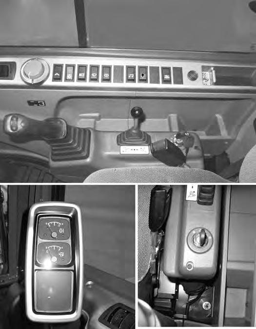
Right Console
Figure9
Right Console [Figure9]
REF.
NO. DESCRIPTION FUNCTION / OPERATION
1 Right Joystick(See HYDRAULIC CONTROLS on Page 50.)
2 Auxiliary Hydraulic Switch
Controls the fluid flow to the auxiliary hydraulic quick couplers (attachment) (See Auxiliary Hydraulics (One Way Flow) on Page 52.)
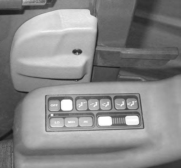
3 Blade Control Lever Blade Control: Controls raising and lowering the blade. (See BLADE CONTROL LEVER on Page 54.)
4 Engine Speed Control Dial Controls rpm of the engine. (See Engine Speed Control Dial on Page 39.)
5 Key SwitchAlways perform the PRESTARTING PROCEDURE before starting the engine. (See PRESTARTING PROCEDURE on Page 59.) and (See STARTING THE ENGINE on Page 62.)
6 Auxiliary Power Outlet 12 volt receptacle for accessories.
7 Two-Speed Switch Engages and disengages High Range Travel Speed. (See TwoSpeed Travel on Page 39.)
8 Auto Idle Switch
Engages and disengages the automatic idle feature. (See Engine Speed Control Dial on Page 39.)
9 Light Switch OFF- ON - ON Press switch to centre position to turn instrument panel lights ON, press switch fully to activate cab work lights and boom work lights.
10 Wiper Switch OFF- ON - ON Press switch to centre position for intermittent wiper mode, press switch fully for continuous wiper motion.
11 Window Washer Switch
Press switch to spray washer fluid on the front window. (Will only work when the wiper switch is ON.)
12 Radio ON / OFF Switch Turns the main power On or OFF to the radio. (The key switch must also be in the ON position for the radio to be powered.)
13 Overload Warning Engages or disengages the overload warning feature. (See OVERLOAD WARNING on Page 55.)
14 Beacon / Strobe Light Switch (OPTIONAL)
15 Motion Alarm Cancel Switch (OPTIONAL)
16 Engine Emergency Stop Switch
Press switch to turn strobe / beacon light ON (if equipped).
Engages or disengages the motion alarm (if equipped). (See MOTION ALARM SYSTEM (IF EQUIPPED) on Page 49.)
Move the switch to the emergency STOP position. Switch will return to the ON position when released.
17 NANot used for this model.
18 HourmeterShows total hours of machine use.
19 Instrument Panel (See Function Icons on Page 37.)
NOTE:Always turn key switch and all accessories to OFF position after the engine is stopped. The battery will discharge if the key is left ON.