
16 minute read
MAINTENANCE SAFETY


Instructions are necessary before operating or servicing machine. Read and understand the Operation & Maintenance Manual, Operator’s Handbook and signs (decals) on machine. Follow warnings and instructions in the manuals when making repairs, adjustments or servicing. Check for correct function after adjustments, repairs or service. Untrained operators and failure to follow instructions can cause injury or death.
W-2003-0807
Safety Alert Symbol: This symbol with a warning statement, means: “Warning, be alert! Your safety is involved!” Carefully read the message that follows.
Never service the Bobcat Excavator without instructions.
Use the correct procedure to lift and support the excavator.
Cleaning and maintenance are required daily.
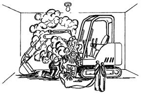
Have good ventilation when welding or grinding painted parts. Wear dust mask when grinding painted parts. Toxic dust and gas can be produced.
Vent exhaust to outside when engine must be run for service. Exhaust system must be tightly sealed. Exhaust fumes can kill without warning.
Always lower the bucket and blade to the ground before doing any maintenance. Never modify equipment or add attachments not approved by Bobcat Company.
Stop, cool and clean engine of flammable materials before checking fluids. Never service or adjust machine with the engine running unless instructed to do so in the manual.
Avoid contact with leaking hydraulic fluid or diesel fuel under pressure. It can penetrate the skin or eyes.
Never fill fuel tank with engine running, while smoking, or when near open flame.
Keep body, jewelry and clothing away from moving parts, electrical contact, hot parts and exhaust. Wear eye protection to guard from battery acid, compressed springs, fluids under pressure and flying debris when engines are running or tools are used. Use eye protections approved for type of welding. Keep tailgate closed except for service. Close and latch tailgate before operating the excavator.
Lead-acid batteries produce flammable and explosive gases. Keep arcs, sparks, flames and lighted tobacco away from batteries.
Batteries contain acid which burns eyes or skin on contact. Wear protective clothing. If acid contacts body, flush well with water. For eye contact flush well and get immediate medical attention.
Maintenance procedures which are given in the Operation & Maintenance Manual can be performed by the owner/ operator without any specific technical training. Maintenance procedures which are not in the Operation & Maintenance Manual must be performed ONLY BY QUALIFIED BOBCAT SERVICE PERSONNEL. Always use genuine Bobcat replacement parts. The Service Safety Training Course is available from your Bobcat dealer.
MSW28-0409

Service Schedule
Chart
Maintenance work must be done at regular intervals. Failure to do so will result in excessive wear and early failures. The service schedule is a guide for correct maintenance of the Bobcat excavator.
WARNING
Engine Oil
Hydraulic Fluid, Hoses and Tubelines, Reservoir Breather Cap
Instructions are necessary before operating or servicing machine. Read and understand the Operation & Maintenance Manual, Operator’s Handbook and signs (decals) on machine. Follow warnings and instructions in the manuals when making repairs, adjustments or servicing. Check for correct function after adjustments, repairs or service. Untrained operators and failure to follow instructions can cause injury or death. W-2003-0807
SERVICE SCHEDULE
Check coolant level. Add premixed coolant as needed.
Check the engine oil level and add as needed.
Check the hydraulic fluid level and add as needed. Check for damage and leaks. Repair or replace as needed.
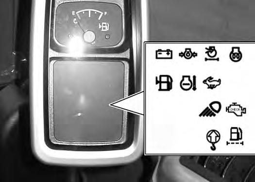
Engine Air Filter and Air SystemCheck condition indicator and empty dust cup as needed. Check air system for leaks.
Tracks
Indicators and Lights
Operator Cab
Seat Belt
Console Lockout
Safety Signs
Fuel Tank And Filter
Check and adjust track tension as needed.
Check for correct operation of all indicators and lights.
Check condition. Check mounting hardware.
Check condition. Check mounting hardware.
Check console lockout for proper operation. Repair or replace as needed.
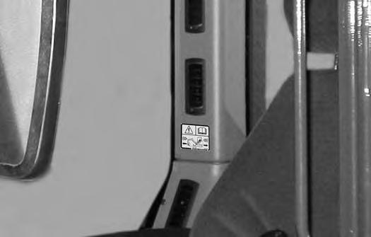
Check for damaged signs (decals). Replace any signs that are damaged.
Drain water and sediment from fuel tank and fuel filter.
Swing Circle Grease the fitting. [1]
Pivot Points Grease blade, boom swing, boom swing cylinder pivot points and the front attachment pins. [1] [2]
Battery Check battery, cables, connections and electrolyte level. Add distilled water as needed.
Fuel Tank Drain water and sediment from fuel tank.
Spark Arrester Muffler Clean spark chamber.
[2] Fuel Filters
Oil and
Clean
Travel Motor Check the oil level in both travel motors
Circle Pinion Grease the fitting.
Oil Cooler,
A/C condition of belt and idlers. Adjust as needed.
Replace fuel filter.
Cab Heater Air Filters Clean the filter as needed.
Hydraulic
Engine
[1] Service every 10 hours when operating in water.
[2] Service every 10 hours for the first 100 hours, then as scheduled.
[3] Service at the first 50 hours, then as scheduled. [4] Service at the first 100 hours, then as scheduled.
[5] Service at the first 250 hours, then as scheduled.
[6] Or every 12 months.
[7] Service at the first year, then as scheduled.
HOURS
[6]
SERVICE SCHEDULE (CONT’D)
Inspection Checkbook
Regularly scheduled maintenance is essential to continuous operation and operating safety. The life expectancy of your machine depends on proper and meticulous care.
The Inspection Checkbook contains the following information:
Doosan Benelux S.A. Warranty Conditions
Protection Plus Extended Warranty Conditions
General Parts Policy
General Information
First Inspection
Scheduled Services
Identification
Authorised Identification
Lubricants and Fluids Table Service Parts Chart
Your local dealer can order the Inspection Checkbook. Part number: 4420310.
Control Console Lockout
Inspection And Maintenance
Figure135
When the left console is raised [Figure135] the hydraulic control levers (joysticks and traction system) must not function.
Sit in the operator's seat, fasten the seat belt and start the engine.
Raise the left console.
Move the joystick control levers. There should be no movement of the boom, arm, slew or bucket.
Move the travel control levers. There should be no movement of the excavator.
Service the system if these controls do not deactivate when the left control console is raised. (See your Bobcat dealer for service.)
Failure to properly inspect and maintain the seat belt can cause lack of operator restraint resulting in serious injury or death.
W-2466-0703
Check the seat belt daily for correct function.
Inspect the seat belt system thoroughly at least once each year or more often if the machine is exposed to severe environmental conditions or applications.
Any seat belt system that shows cuts, fraying, extreme or unusual wear, significant discolourations due to ultraviolet UV exposure, dusty / dirty conditions, abrasion to the seat belt webbing, or damage to the buckle, latch plate, retractor (if equipped), hardware or any other obvious problem should be replaced immediately.

The items below are referenced in [Figure136]
1.Check the webbing. If the system is equipped with a retractor, pull the webbing completely out and inspect the full length of the webbing. Look for cuts, wear, fraying, dirt and stiffness.
2.Check the buckle and latch for correct operation. Make sure latch plate is not excessively worn, deformed or buckle is not damaged or casing broken.
3.Check the retractor web storage device (if equipped) by extending webbing to determine if it looks correct and that it spools out and retracts webbing correctly.
4.Check webbing in areas exposed to ultraviolet (UV) rays from the sun or extreme dust or dirt. If the original colour of the webbing in these areas is extremely faded and / or the webbing is packed with dirt, the webbing strength may have deteriorated.
See your Bobcat dealer for seat belt system replacement parts for your machine.
MOTION ALARM SYSTEM Description
This excavator may be equipped with a motion alarm system. The motion alarm (when the motion alarm cancel switch is in the ON position) will sound when the operator moves the travel control levers in the either the forward or reverse direction. Slight movement of the steering levers in either the forward or reverse direction is required with hydraulic components before the motion alarm will sound.
Inspecting
Figure137
Inspect for damaged or missing motion alarm decal (Item 1) [Figure137]. Replace if required.
NOTE:The excavator will need to be moved slightly in both the forward and reverse direction to test the motion alarm. Keep all bystanders away from machine during test.
Make sure there are no bystanders in the area.
Warning
Avoid Injury Or Death
When an engine is running in an enclosed area, fresh air must be added to avoid concentration of exhaust fumes. If the engine is stationary, vent the exhaust outside. Exhaust fumes contain odorless, invisible gases which can kill without warning.
W-2050-0807
Sit in the operator’s seat and fasten the seat belt. Start the engine. (See PRE-STARTING PROCEDURE on Page 59.)
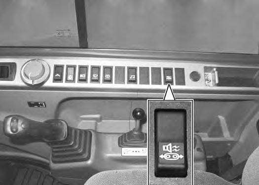
Make sure the motion alarm switch (Item 1) [Figure138] is in the ON position.
Move the travel control levers (one lever at a time) in the forward direction. The motion alarm must sound. Move the travel control levers (one lever at a time) in the reverse direction. The motion alarm must sound.
Return both levers to neutral and turn excavator key to OFF position. Exit the excavator. (See STOPPING THE ENGINE AND LEAVING THE EXCAVATOR on Page 65.)
MOTION ALARM SYSTEM (CONT’D)
Inspecting (Cont’d)
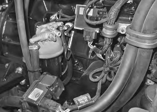
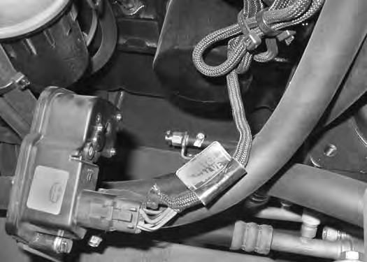
The motion alarm is located inside the lower part of the engine compartment.
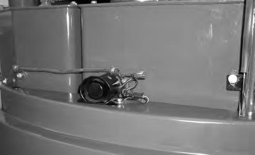
Figure139
Inspect the motion alarm electrical connector (Item 1) and wire harness (Item 2) [Figure139] for damage. Repair or replace any damaged components.

If the motion alarm switch requires adjustment, see the following information.
Adjusting Switch Position
Stop the engine. Raise the operator cab. (See Service Manual for correct procedure.)
Figure140
The motion alarm switch (Item 1) [Figure140] is hydraulic pressure activated and
Inspect the motion alarm system for proper function if switch is replaced.
This machine is equipped with a motion alarm. ALARM MUST SOUND! when operating forward or backward.
Failure to maintain a clear view in the direction of travel could result in serious injury or death.
The operator is responsible for the safe operation of this machine.
Rear Cover
Opening And Closing
The hydraulic tank breather / filter and hydraulic oil fill cover is located under the rear cover.
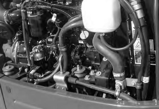

Figure141
Use the start key to unlock and open the rear cover (Item 1) [Figure141]
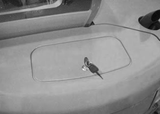
Close and lock the rear cover when the service procedure is completed.
Right Side Cover
Opening And Closing
Figure142
Pull the latch (Item 1) [Figure142] and raise the right side cover.
NOTE: The right side cover can be locked using the start key.
Adjusting The Latch
Figure143
The right side cover latch (Item 1) [Figure143] can be adjusted.
Loosen the nut (Item 2) [Figure143] and adjust the latch. Tighten the nut after the adjustment is made.
Close the right side cover before operating the excavator.
Cab Filters
Cleaning And Maintenance
See the SERVICE SCHEDULE for the correct service interval. (See SERVICE SCHEDULE on Page 95.)
The recirculation filter must be cleaned regularly. The filter is located below the operator seat.
Remove the four bolts (Item 1) from the cover (Item 2) [Figure144]

Installation: Install the filter with the arrows that indicate air flow direction (Item 1) [Figure146] pointing towards the heater / A/C housing.
The filter must be cleaned regularly.
Remove the cover (Item 1) and pull up the filter (Item 2) [Figure145] to remove from the cover.
Use low air pressure to clean the filter. Replace the filter when very dirty.
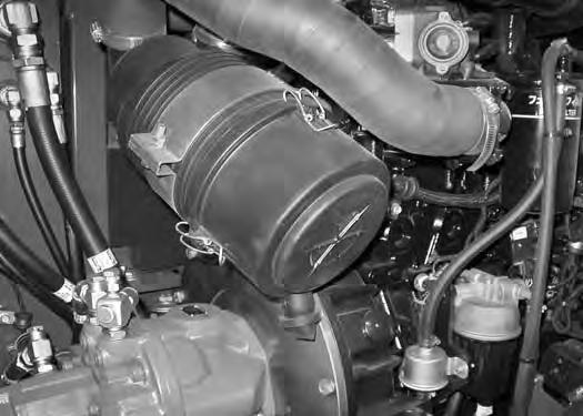
Air Cleaner Service
See the SERVICE SCHEDULE for the correct service interval. (See SERVICE SCHEDULE on Page 95.)
Daily Check
Figure147
Check the air cleaner condition indicator icon (Item 1) [Figure147] in the instrument panel. If the icon stays ON after the engine is started, the filter needs to be replaced.
Replacing Filter Elements
Open the right side cover to access the air cleaner for service. (See RIGHT SIDE COVER on Page 100.)
Figure148
Replace the inner filter every third time the outer filter is replaced or as indicated.

Outer Filter
Pull out on the three fasteners (Item 1) and remove the cover [Figure148]
Clean the dust cup (Item 2) [Figure148].
Figure149
Pull the outer filter (Item 1) [Figure149] from the air cleaner housing.
Check the housing for damage.
Clean the housing and the seal surface. DO NOT use compressed air.
Install a new filter.
Install the cover and engage the three fastener (Item 1) [Figure148]
Make sure the dust evacuator cup (Item 3) [Figure148] is in the down position as shown.
Check the air intake hose and the air cleaner housing for damage. Make sure all connections are tight.
AIR CLEANER SERVICE (CONT’D)
Replacing Filter Elements (Cont’d)
Inner Filter
Only replace the inner filter under the following conditions:
•Replace the inner filter every third time the outer filter is replaced.
•After the outer filter has been replaced, start the engine. If the air cleaner condition indicator icon (Item 1) [Figure147] remains ON, replace the inner filter.

Remove the air cleaner cover, the outer filter and the inner filter (Item 1) [Figure150]
NOTE: Make sure all sealing surfaces are free of dirt and debris. DO NOT use compressed air.
Install the new inner filter (Item 1) [Figure150]
Install the outer filter and the air cleaner cover.
Fuel System
Use only clean, high quality diesel fuel, Grade No. 2 or Grade No. 1 with a cetane number of 45 or higher.
The following is a suggested blending guideline which should prevent fuel gelling problems during freezing temperature:
Biodiesel Blend Fuel
Biodiesel blend fuel has unique qualities that should be considered before using in this machine:
•Cold weather conditions can lead to plugged fuel system components and hard starting.
•Biodiesel blend fuel is an excellent medium for microbial growth and contamination which can cause corrosion and plugging of fuel system components.
•Use of biodiesel blend fuel may result in premature failure of fuel system components, such as plugged fuel filters and deteriorated fuel lines.
At a minimum, low sulfur diesel fuel must be used in this machine. Low sulfur is defined as 500 mg/kg (500 ppm) sulfur maximum.
The following fuels may also be used in this machine:
•Ultra low sulfur diesel fuel. Ultra low sulfur is defined as 15 mg/kg (15 ppm) sulfur maximum.
•Biodiesel Blend Fuel - Must contain no more than five percent biodiesel mixed with low sulfur or ultra low sulfur petroleum based diesel. This is commonly marketed as B5 blended diesel fuel.
Warning
AVOID INJURY OR DEATH
Stop and cool the engine before adding fuel. NO SMOKING! Failure to obey warnings can cause an explosion or fire.
W-2063-0807
Warning
AVOID INJURY OR DEATH
Always clean up spilled fuel or oil. Keep heat, flames, sparks or lighted tobacco away from fuel and oil. Failure to use care around combustibles can cause explosion or fire.
W-2103-0508
•Shorter maintenance intervals may be required, such as cleaning the fuel system and replacing fuel filters and fuel lines.
•Using biodiesel blended fuels containing more than five percent biodiesel can affect engine life and cause deterioration of hoses, tubelines, injectors, injector pump and seals.
Apply the following guidelines if biodiesel blend fuel is used:
•Ensure the fuel tank is as full as possible at all times to prevent moisture from collecting in the fuel tank.
•Ensure that the fuel tank cap is securely tightened.
•Biodiesel blend fuel can damage painted surfaces, remove all spilled fuel from painted surfaces immediately.
•Drain all water from the fuel filter daily before operating the machine.
•Do not exceed engine oil change interval. Extended oil change intervals can cause engine damage.
•Before vehicle storage; drain the fuel tank, refill with 100% petroleum diesel fuel, add fuel stabilizer and run the engine for at least 30 minutes.
NOTE:Biodiesel blend fuel does not have long term stability and should not be stored for more than three months.
FUEL SYSTEM (CONT’D)
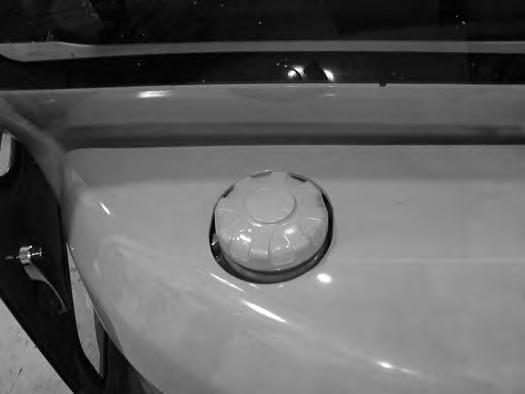
Filling The Fuel Tank
Inspect
Use a clean, approved safety container to add fuel. Add fuel only in an area that has a free movement of air and no flames or sparks. NO SMOKING!
Install and tighten the fuel fill cap.
Clean up any spilled fuel.
FUEL SYSTEM (CONT’D)
Fuel Filters
Removing Water
See the SERVICE SCHEDULE for the service interval when to remove water from or replace the fuel filter. (See SERVICE SCHEDULE on Page 95.)
Open the right side cover. (See RIGHT SIDE COVER on Page 100.)
Replacing Elements
See the SERVICE SCHEDULE for the service interval when to replace the fuel filter. (See SERVICE SCHEDULE on Page 95.)
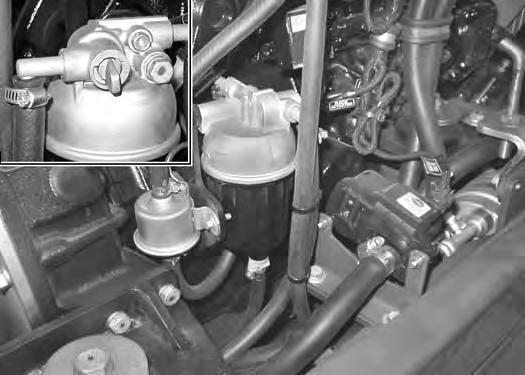
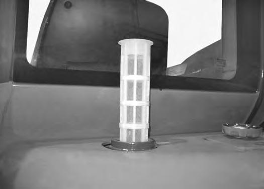
Fuel Water Separator
Turn the shut off valve (Item 2) [Figure153] clock wise to the closed position.
Remove the housing (Item 3) [Figure153] and replace the screen.
Clean the area around the filter housing. Put clean oil on the seal of the new filter. Install the fuel filter and hand tighten.
Turn the shut off valve (Item 2) [Figure153] anticlockwise to the open position.
Figure154
Loosen the drain (Item 1) [Figure153] at the bottom of the filter to drain water from the filter into a container.‘
Clean up any spilled fuel.
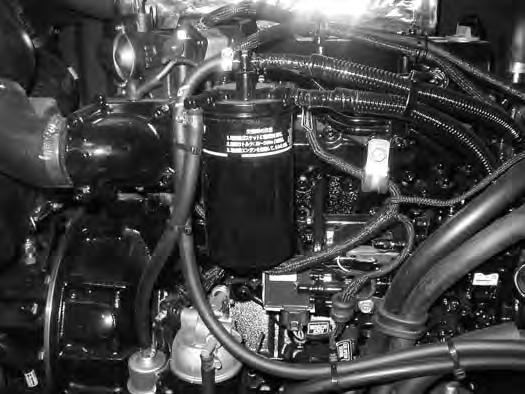
Fuel Filter
Turn the shut off valve (Item 2) [Figure153] clock wise to the closed position.
Remove the filter (Item 1) [Figure154]
Clean the area around the filter housing. Put clean oil on the seal of the new filter. Install the fuel filter and hand tighten.
Turn the shut off valve (Item 2) [Figure153] anticlockwise to the open position.
Remove the air from the fuel system. (See Removing Air From The Fuel System on Page 107.)
FUEL SYSTEM (CONT’D)
Draining The Fuel Tank
See the SERVICE SCHEDULE for the correct service interval. (See SERVICE SCHEDULE on Page 95.)
Avoid Injury Or Death
Diesel fuel or hydraulic fluid under pressure can penetrate skin or eyes, causing serious injury or death. Fluid leaks under pressure may not be visible. Use a piece of cardboard or wood to find leaks. Do not use your bare hand. Wear safety goggles. If fluid enters skin or eyes, get immediate medical attention from a doctor familiar with this injury.
W-2072-EN-0909
Removing Air From The Fuel System
After replacing the fuel filter or when the fuel tank has run out of fuel, air must be removed from the fuel system before starting the engine.
Turn the start key to the ON position for 10 - 15 seconds.
The electric fuel pump will supply fuel under pressure and force air from the system.
Install
Drain the fuel into a container. Tighten the drain valve after fuel has been removed.
Reuse, recycle or dispose of fuel in an environmentally safe manner.
Engine Lubrication System
Checking And Adding Engine Oil
Check the engine oil every day before starting the engine for the work shift.
Figure157
Open the right side cover and remove the dipstick (Item 1) [Figure157]
Keep the oil level between the marks on the dipstick.
Engine Oil Chart
Figure 158
RECOMMENDED SAE VISCOSITY NUMBER
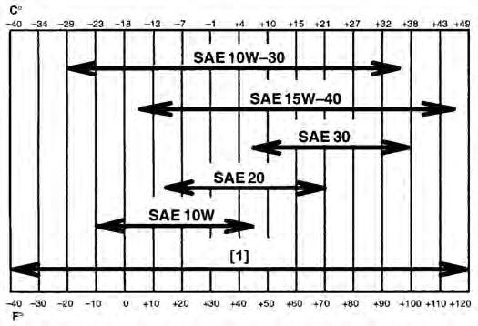
(LUBRICATION OILS FOR DIESEL ENGINE CRANKCASE)
TEMPERATURE RANGE ANTICIPATED BEFORE NEXT OIL CHANGE (DIESEL ENGINES MUST USE API CLASSIFICATION CI-4 OR BETTER)
[1] Synthetic Oil - Use recommendation from Synthetic Oil Manufacturer.
Use good quality engine oil that meets API Service Classification of CI-4 or better [Figure 158]
Warning
AVOID INJURY OR DEATH
Always clean up spilled fuel or oil. Keep heat, flames, sparks or lighted tobacco away from fuel and oil. Failure to use care around combustibles can cause explosion or fire.
W-2103-0508
Install the dipstick and close the right side cover.
ENGINE LUBRICATION SYSTEM (CONT’D)
Removing And Replacing Oil And Filter
See the SERVICE SCHEDULE for the service interval for replacing the engine oil and filter. (See SERVICE SCHEDULE on Page 95.)
Run the engine until it is at operating temperature. Rotate the upperstructure 90° for access to the bottom engine cover and the engine oil pan drain plug. Stop the engine. Open the right side cover.
From under the machine, loosen the two bolts (Item 1) and remove four bolts / washers (Item 2) from the access cover (Item 3) [Figure159] from below the engine area. Remove the access cover.
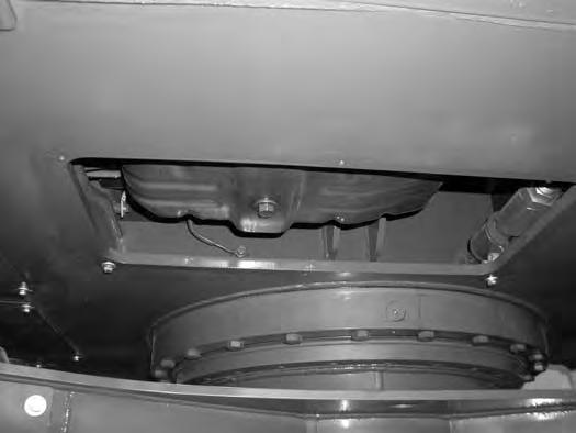

Remove the oil filter (Item 1) [Figure161] and clean the filter housing surface.
Use a genuine Bobcat replacement filter. Put clean oil on the filter gasket. Install the filter and hand tighten.
Install and tighten the plug (Item 1) [Figure160]
Remove the plug (Item 1) [Figure160] from the engine oil pan. Drain the oil into a container.
Recycle or dispose of used oil in an environmentally safe manner.
Remove the fill cap (Item 1) [Figure162]
Put the correct amount of oil in the engine. (See Capacities on Page 154.)
Install the fill cap.
Start the engine and let it run for several minutes. Stop the engine. Check for leaks at the oil filter. Check the oil level.
Add oil as needed if it is not at the top mark on the dipstick.
Reinstall the access cover (Item 3) [Figure159] and tighten the bolts.
ENGINE COOLING SYSTEM
Check the cooling system every day to prevent overheating, loss of performance or engine damage.
Cleaning
Open the right side cover. (See RIGHT SIDE COVER on Page 100.)
Figure163
Use air pressure or water pressure to clean the radiator, oil cooler and the air conditioning condenser (Item 1) [Figure163]. Be careful not to damage fins when cleaning.

NOTE: Allow the cooling system and engine to cool before servicing or cleaning the cooling system.
Checking Level
Warning
AVOID BURNS
Do not remove radiator cap when the engine is hot. You can be seriously burned.
W-2070-1203
Warning
AVOID INJURY OR DEATH
Wear safety glasses to prevent eye injury when any of the following conditions exist:
•When fluids are under pressure.
•Flying debris or loose material is present.
•Engine is running.
•Tools are being used.
Open the right side cover.
W-2019-0907
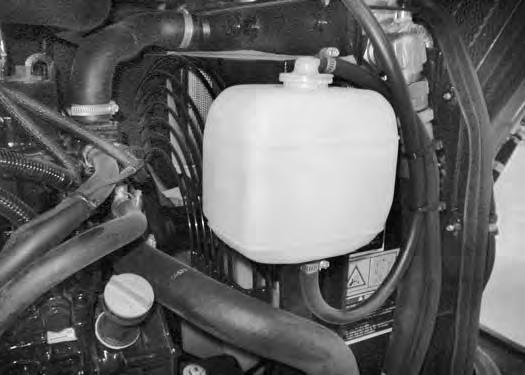
Check the coolant level in the coolant recovery tank (Item 1) [Figure164]
The coolant level must be between the MIN and MAX marks on the coolant recovery tank (Item 1) [Figure164] when the engine is cold.
NOTE: The cooling system is factory filled with ethylene glycol. DO NOT mix ethylene glycol with propylene glycol.
Important
AVOID ENGINE DAMAGE
Always use the correct ratio of water to antifreeze.
Too much antifreeze reduces cooling system efficiency and may cause serious premature engine damage.
Too little antifreeze reduces the additives which protect the internal engine components; reduces the boiling point and freeze protection of the system.
Always add a premixed solution. Adding full strength concentrated coolant can cause serious premature engine damage.
I-2124-0497
ENGINE COOLING SYSTEM (CONT’D)
Removing And Replacing Coolant
See the SERVICE SCHEDULE for correct service intervals. (See SERVICE SCHEDULE on Page 95.)
Stop the engine. Open the right side cover. (See RIGHT SIDE COVER on Page 100.)
Warning
AVOID BURNS
Do not remove radiator cap when the engine is hot. You can be seriously burned.
Open the drain valve (Item 1) [Figure166] (located below the oil filter) and drain the coolant into the container.
After all the coolant is removed, close the drain valve. Recycle or dispose of the used coolant in an environmentally safe manner.
Mix the coolant in a separate container. (See Capacities on Page 154.)
NOTE: The cooling system is factory filled with ethylene glycol. DO NOT mix ethylene glycol with propylene glycol.
The correct mixture of coolant to provide a -37°C (-34°F) freeze protection is 4 L ethylene glycol mixed with 4 L of water OR 1 U.S. gal ethylene glycol mixed with 1 U.S. gal of water.
When the engine is cool, loosen and remove the radiator cap (Item 1) [Figure165]
Rotate the upperstructure 90° to access the lower engine access cover. Remove the lower engine access cover so coolant can be drained into a container.

Add premixed coolant; 50% water and 50% ethylene glycol to the recovery tank if the coolant level is low.
Add premixed coolant until the level is correct.
Run the engine until it is at operating temperature. Stop the engine. Check the coolant level and add as needed. Be sure the radiator cap is tight.
Add coolant to the recovery tank as needed.
Reinstall the lower engine access cover.
Close the right side cover.