16 minute read
ELECTRICAL SYSTEM


Description
Figure167
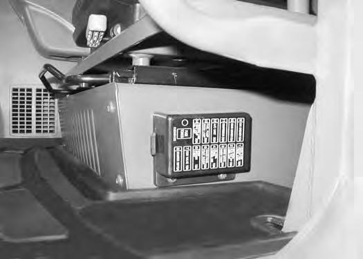
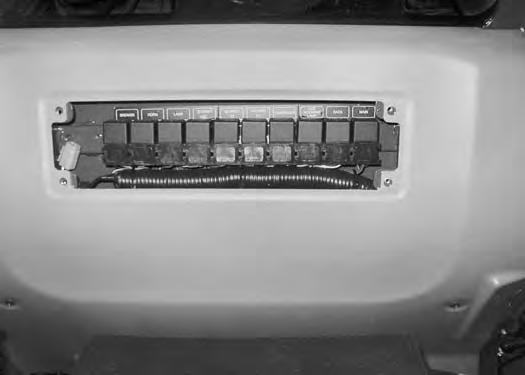
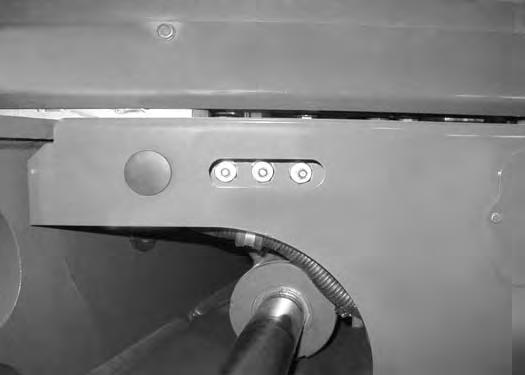
The excavator has a 12 volt, negative ground electrical system. The electrical system is protected by fuses located below the operator’s seat (Item 1) [Figure167] The fuses will protect the electrical system when there is an electrical overload. The reason for the overload must be found before starting the engine again.
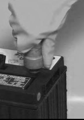
The battery cables must be clean and tight. Check the electrolyte level in the battery. Add distilled water as needed. Remove acid or corrosion from the battery and cables with a sodium bicarbonate and water solution.
Put Battery Saver P/N 6664458 or grease on the battery terminals and cable ends to prevent corrosion.
Warning
AVOID INJURY OR DEATH
Batteries contain acid which burns eyes and skin on contact. Wear goggles, protective clothing and rubber gloves to keep acid off body.
In case of acid contact, wash immediately with water. In case of eye contact get prompt medical attention and wash eye with clean, cool water for at least 15 minutes.
If electrolyte is taken internally drink large quantities of water or milk! DO NOT induce vomiting. Get prompt medical attention.
W-2065-0807
Fuse And Relay Location / Identification
A decal is on the cover to show location and amp ratings.
Remove the cover to check or replace the fuses.
Figure168
The fuse location and sizes are shown [Figure168] and in the below chart.
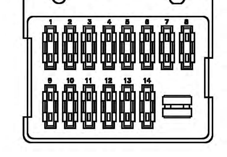
1Warning
2Two-Speed,
3Wiper,
4Stereo,
5Instrument
6Horn,
ELECTRICAL SYSTEM (CONT’D)
Fuse And Relay Location / Identification (Cont’d)
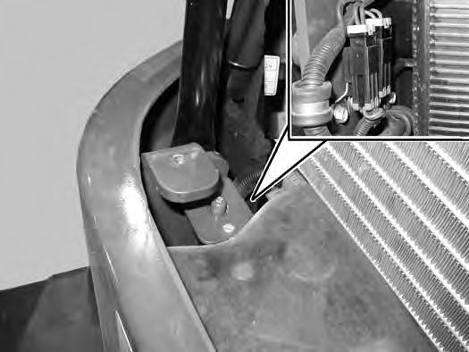
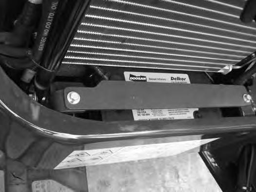
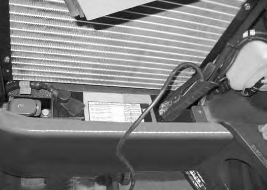
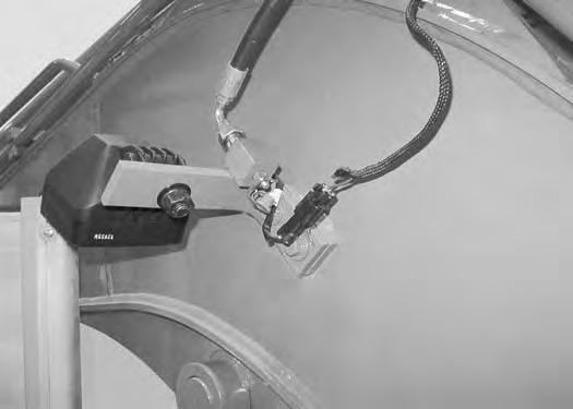
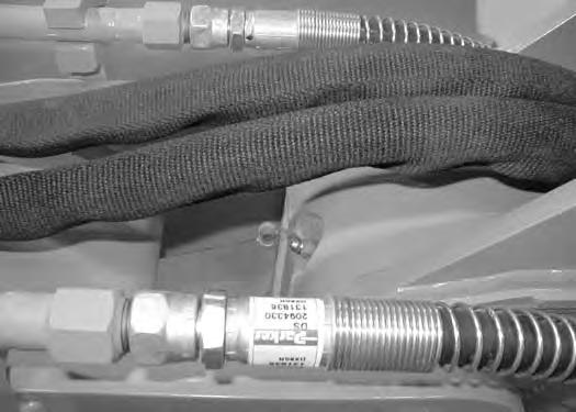
A 60 amp circuit breaker (Item 1) and two fusible links (Item 2) 27 amp and (Item 3) 45 amp [Figure169] are located by the battery.
The 27 amp fusible link (Item 2) is for the start circuit and the 45 amp fusible link (Item 3) [Figure169] is for the pre-heat circuit.
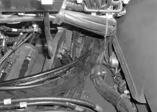
The relays are shown in [Figure170] and [Figure171] and in the below chart. The relays are located behind the access panel that is located behind the operator’s seat.
REF DESCRIPTION
1Breaker Switch
2Horn
3Lights (Boom)
4Blower (3) (High)
5Blower (2) (Med)
6Blower (1) (Lo)
7Compressor
8Additional Lights (Cab Work Lights)
9Rack (Speed Control) 10Main 11Pre-Heat 12Starter
NOTE: Relays (Item 11 and 12) [Figure171] are located under the cab.
Open the right side cover.
ELECTRICAL SYSTEM (CONT’D)
Battery Maintenance
Open the right side cover. (See RIGHT SIDE COVER on Page 100.)
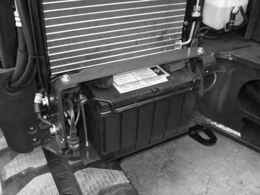
The battery is located in the right front corner of the machine.
Remove the two bolts and washers (Item 1), the retaining plate (Item 2) [Figure172]
The battery cables must be clean and tight [Figure173] Remove acid or corrosion from the battery and cables using a sodium bicarbonate and water solution. Cover the battery terminals and cable ends with battery saver grease to prevent corrosion.
Check for broken or loose connections.
If the battery cables are removed for any reason, disconnect the negative (-) cable first. When installing the battery cables, make the last connection the negative (-) cable to the battery.
The original equipment battery is maintenance free. If a replacement battery is installed, check the electrolyte level in the battery.
If the electrolyte level is lower than 13 mm (0.50 in) above the plates, add distilled water only.
Warning
Avoid Injury Or Death
Batteries contain acid which burns eyes and skin on contact. Wear goggles, protective clothing and rubber gloves to keep acid off body.
In case of acid contact, wash immediately with water. In case of eye contact get prompt medical attention and wash eye with clean, cool water for at least 15 minutes.
If electrolyte is taken internally drink large quantities of water or milk! DO NOT induce vomiting. Get prompt medical attention.
W-2065-0807
ELECTRICAL SYSTEM (CONT’D)
Using A Booster Battery (Jump Starting)
If it is necessary to use a booster battery to start the engine, BE CAREFUL! There must be one person in the operator's seat and one person to connect and disconnect the battery cables.
Be sure the key switch is OFF. The booster battery must be 12 volt.
Open the right side cover.
Connect one end of the first cable to the positive (+) terminal of the booster battery. Connect the other end of the same cable to the positive (+) terminal (Item 1) [Figure174] of the battery.
Connect one end of the second cable to the negative (-) terminal of the booster battery. Connect the other end of the same cable to bolt (Item 2) [Figure175] where the flywheel cover fastened to the engine.
Start the engine. After the engine has started, remove the ground (-) cable first (Item 2) [Figure174]
Disconnect the cable from the battery (Item 1) [Figure174].
NOTE: (See Cold Temperature Starting on Page 63.)
Important
Damage to the alternator can occur if:

•Engine is operated with battery cables disconnected.
•Battery cables are connected when using a fast charger or when welding on the excavator. (Remove both cables from the battery.)
•Extra battery cables (booster cables) are connected wrong.
I-2223-0903
Warning
AVOID INJURY OR DEATH
Batteries contain acid which burns eyes and skin on contact. Wear goggles, protective clothing and rubber gloves to keep acid off body.
In case of acid contact, wash immediately with water. In case of eye contact get prompt medical attention and wash eye with clean, cool water for at least 15 minutes.
If electrolyte is taken internally drink large quantities of water or milk! DO NOT induce vomiting. Get prompt medical attention.
W-2065-0807
ELECTRICAL SYSTEM (CONT’D)
Removing And Installing Battery
Open the right side cover. (See RIGHT SIDE COVER on Page 100.)
Remove the three plugs (Item 1) [Figure176] and the bolts and washers.
Loosen the three bolts (Item 2) and remove the cover (Item 3) [Figure176]
NOTE:There may be washers used as shims between the bolts (Item 2), the upperstructure and the cover (Item 3) [Figure176].

Remove the two bolts and washers (Item 1), the retaining plate (Item 2) [Figure177] and the plastic cover.
Disconnect the negative (-) cable (Item 3) [Figure177] first.
Disconnect the positive (+) cable (Item 4) [Figure177]
Remove the two nuts (Item 5) and remove the hold down clamp (Item 6) [Figure177]
Remove the battery.
Always clean the terminals and the cable ends, even when installing a new battery.
Install the battery. Install the hold down clamp and tighten the bolts.
Connect the battery cables. Connect the negative (-) cable (Item 3) [Figure177] last to prevent sparks.
Warning
Avoid Injury Or Death
Batteries contain acid which burns eyes and skin on contact. Wear goggles, protective clothing and rubber gloves to keep acid off body.
In case of acid contact, wash immediately with water. In case of eye contact get prompt medical attention and wash eye with clean, cool water for at least 15 minutes.
If electrolyte is taken internally drink large quantities of water or milk! DO NOT induce vomiting. Get prompt medical attention.
W-2065-0807
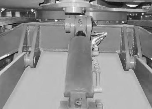
HYDRAULIC SYSTEM Checking And Adding Fluid
Put the machine on a level surface.
Retract the arm and bucket cylinders, put the bucket on the ground and lower the blade. Stop the engine.
Open the right side cover. (See RIGHT SIDE COVER on Page 100.)
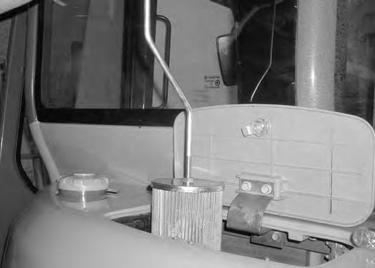
Check the hydraulic fluid level, it must be visible in the sight gauge (Item 1) between the two red lines (Item 2) [Figure178]
Warning
AVOID INJURY OR DEATH
Always clean up spilled fuel or oil. Keep heat, flames, sparks or lighted tobacco away from fuel and oil. Failure to use care around combustibles can cause explosion or fire.
Open the rear cover. (See REAR COVER on Page 100.)
NOTE:When removing the cover (Item 2), there is spring pressure under the cover. Push down on the cover while removing the bolts (Item 3) [Figure179].
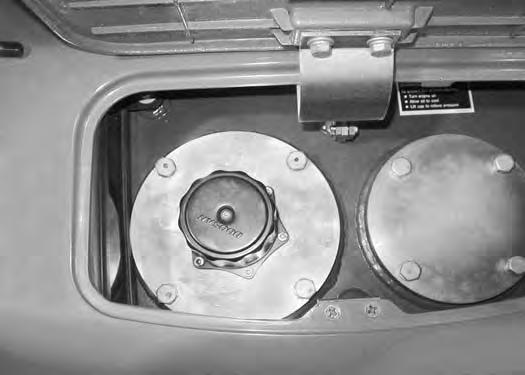
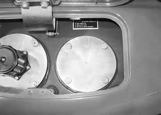
Clean the surface around the reservoir (breather) cap (Item 1) and cover (Item 2) fully. Press down on the cover (Item 2) and remove the four bolts (Item 3) from the cover (Item 2) [Figure179]. Remove the cover.
Add the correct fluid to the reservoir until it is visible in the sight gauge. (See REGULAR MAINTENANCE ITEMS on Page 9.)
Check the O-ring under the cover (Item 2) [Figure179] Replace the O-ring if damaged.
Reinstall the cover and align the bolt holes. Press down on the cover (Item 2) and install the four bolts (Item 3) [Figure179]. Tighten the bolts.
Close the rear cover.
HYDRAULIC SYSTEM (CONT’D)
Hydraulic Fluid Chart
Figure 180
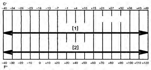
RECOMMENDED ISO VISCOSITY GRADE (VG) AND VISCOSITY INDEX (VI)
TEMPERATURE RANGE ANTICIPATED DURING MACHINE USE
[1] Synthetic Fluid; VG 46; Minimum VI 150
[2] BOBCAT Hydraulic / Hydrostatic Fluid
Use the correct hydraulic fluid shown in chart [Figure 180].
Add hydraulic fluid as needed to bring the level to the centre of sight gauge (Item 1) [Figure178]
Reinstall the cover and align the bolt holes. Press down on the cover (Item 2) and install the four bolts (Item 3) [Figure179]. Tighten the bolts.
HYDRAULIC SYSTEM (CONT’D)
Removing And Replacing Hydraulic Filters
Hydraulic Return Filter
Warning
AVOID INJURY OR DEATH
Always clean up spilled fuel or oil. Keep heat, flames, sparks or lighted tobacco away from fuel and oil. Failure to use care around combustibles can cause explosion or fire.
See the SERVICE SCHEDULE for the correct service interval. (See SERVICE SCHEDULE on Page 95.)
Open the rear cover. (See REAR COVER on Page 100.)
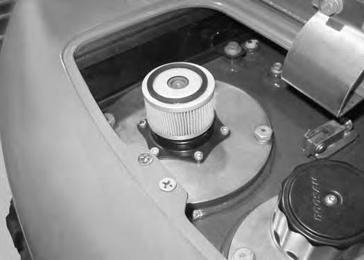
Remove the spring (Item 1) [Figure182]
Inspect the O-ring (Item 2) [Figure182] for damage. Replace if damaged.
NOTE:When removing the cover (Item 2), there is spring pressure under the cover. Push down on the cover while removing the bolts (Item 1) [Figure181].

Clean the surface around the cover (Item 2) [Figure181] fully.
Press down on the cover (Item 2) and remove the four bolts (Item 1) [Figure181] and remove the cover.
Remove the valve (Item 1) [Figure183]
HYDRAULIC SYSTEM (CONT’D)
Removing And Replacing Hydraulic Filters (Cont’d)
Hydraulic Return Filter (Cont’d)
Figure184
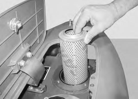
Remove the return filter (Item 1) [Figure184]
Install the new filter (Item 1) [Figure184]
Reinstall the valve (Item 1) [Figure183]
Reinstall the spring (Item 1) [Figure182]
Reinstall the cover and align the bolt holes. Press down on the cover (Item 2) and install the four bolts (Item 1) [Figure181] and tighten the bolts.
Hydraulic Suction Filter
Open the rear cover.
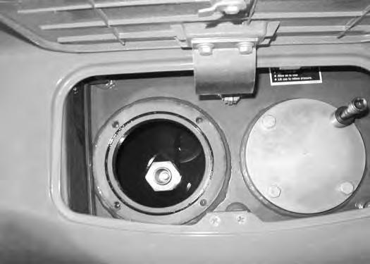
Figure185
NOTE:When removing the cover (Item 2), there is spring pressure under the cover. Push down on the cover while removing the bolts (Item 3) [Figure185].
Clean the surface around the reservoir (breather) cap (Item 1) and cover (Item 2) fully. Remove the four bolts (Item 3) from the cover (Item 2) [Figure185] and remove the cover.
Figure186
Remove the spring (Item 1) [Figure186]
Lift up on the rod (Item 2) [Figure186]
HYDRAULIC SYSTEM (CONT’D)
Removing And Replacing Hydraulic Filters (Cont’d)
Hydraulic Suction Filter (Cont’d)
Figure187
Continue to lift up on the rod (Item 1) until the filter (Item 2) [Figure187] is removed from the tank.
NOTE:Before removing the filter (Item 2) [Figure187] from the rod (Item 1) [Figure187], measure the distance from the end of the rod to the end of the filter. Install the new filter to the same measured distance so that the spring (Item 1) [Figure186] pressure will keep the filter installed correctly in the tank.
NOTE:When installing the new filter (Item 2) [Figure187] into the hydraulic tank, make sure to get the filter positioned over the outlet port at the bottom of the hydraulic tank.
Hydraulic Breather Filter
See the SERVICE SCHEDULE for the correct service interval. (See SERVICE SCHEDULE on Page 95.)
Open the rear cover. (See REAR COVER on Page 100.)
Figure188
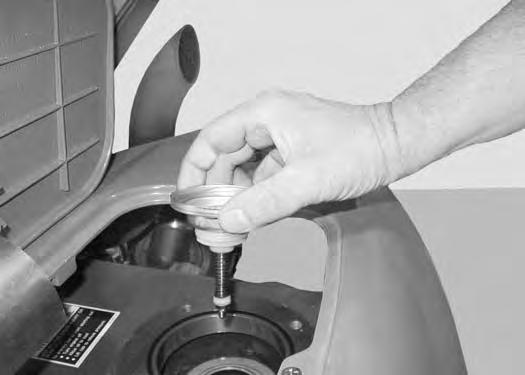
Remove the filter cap (Item 1) [Figure188] by turning the cap anticlockwise.
Remove and replace the breather filter (Item 1) [Figure189]
Reinstall the cap (Item 1) [Figure188]
HYDRAULIC SYSTEM (CONT’D)
Removing And Replacing Hydraulic Fluid
See the SERVICE SCHEDULE for the correct service interval. (See SERVICE SCHEDULE on Page 95.)
Warning
AVOID INJURY OR DEATH
Diesel fuel or hydraulic fluid under pressure can penetrate skin or eyes, causing serious injury or death. Fluid leaks under pressure may not be visible. Use a piece of cardboard or wood to find leaks. Do not use your bare hand. Wear safety goggles. If fluid enters skin or eyes, get immediate medical attention from a doctor familiar with this injury.
W-2072-EN-0909
Retract the arm and bucket cylinders, lower the bucket to the ground. Lower the blade to the ground. Stop the engine.
Open the rear cover. (See REAR COVER on Page 100.)
Figure190
From below the rear of the excavator upperstructure, remove three bolts (Item 1) and loosen the fourth bolt (Item 2) [Figure190].
Rotate the cover plate (Item 1) [Figure191] to access the bottom of the hydraulic tank.
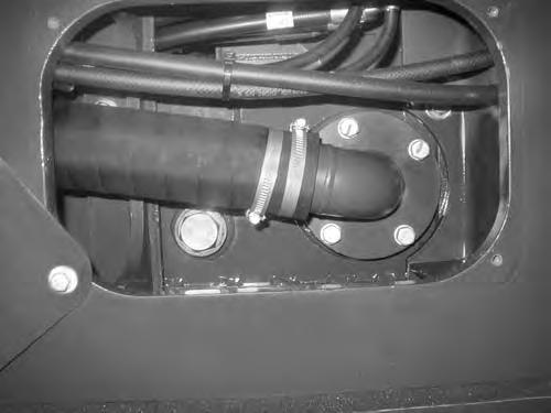
Remove the drain plug (Item 2) [Figure191] from the bottom of the hydraulic tank.
Drain the fluid into a container.
Recycle or dispose of the fluid in an environmentally safe manner.
Reinstall the drain plug (Item 2) [Figure191].
Always replace the filters when changing the hydraulic oil. (See Removing And Replacing Hydraulic Filters on Page 119.)
HYDRAULIC SYSTEM (CONT’D)
Removing And Replacing Hydraulic Fluid
Figure192
After the hydraulic fluid has been drained from the excavator or after the hydraulic pump has been serviced, the hydraulic pump must be flooded with hydraulic oil. Allow sufficient time for the hydraulic fluid to gravity feed into the hydraulic pump before starting the machine.
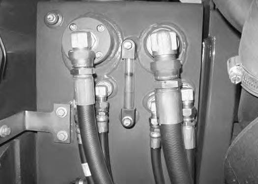
Remove the vent plug (Item 1) [Figure192] to see if hydraulic fluid is at the plug opening. If oil is present the pump has been flooded. Reinstall the vent plug.
If fluid is not at the plug opening, install the plug (Item 1). Start the engine and run at low idle for one minute. Stop the engine. Remove the vent plug (Item 1) [Figure192] and verify fluid is at the plug opening. Reinstall plug before operating.
Recycle or dispose of the fluid in an environmentally safe manner.
Start the engine and operate the machine through the hydraulic functions. Stop the engine. Check the fluid level and add as needed.
Install new Bobcat hydraulic fluid. (See Hydraulic Fluid Chart on Page 118.) (See REGULAR MAINTENANCE ITEMS on Page 9.)

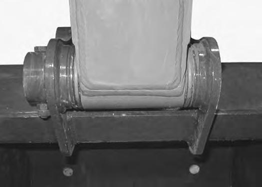
Spark Arrester Muffler
Cleaning Procedure
See the SERVICE SCHEDULE for the correct service interval. (See SERVICE SCHEDULE on Page 95.)
Warning
Avoid Injury Or Death
When an engine is running in an enclosed area, fresh air must be added to avoid concentration of exhaust fumes. If the engine is stationary, vent the exhaust outside. Exhaust fumes contain odorless, invisible gases which can kill without warning.
W-2050-0807
Warning
Stop engine and allow the muffler to cool before cleaning the spark chamber. Wear safety goggles. Failure to obey can cause serious injury.

W-2011-1285
Warning
Never use machine in atmosphere with explosive dust or gases or where exhaust can contact flammable material. Failure to obey warnings can cause injury or death.
W-2068-1285
Warning
When the engine is running during service, the steering levers must be in neutral.
Failure to do so can cause injury or death.
W-2203-0595
Do not operate the excavator with a defective exhaust system.
Stop the engine. Open the tailgate.
Remove the plug (Item 1) [Figure193] from the bottom of the muffler.
Start the engine and run for about 10 seconds while a second person, wearing safety glasses, holds a piece of wood over the outlet of the muffler. The carbon deposits will be forced out of the muffler plug hole (Item 1) [Figure193].
Stop the engine. Install and tighten the plug. Close the right side cover.
Track Tension
NOTE: The wear of undercarriage parts vary with working conditions and types of soil conditions. Maintain the correct track tension by inspecting regularly. For the correct service interval (See SERVICE SCHEDULE on Page 95.)

Adjusting
Figure194
Warning
AVOID INJURY
Keep fingers and hands out of pinch points when checking the track tension.
W-2142-0903
Rubber Track Clearance
Figure196
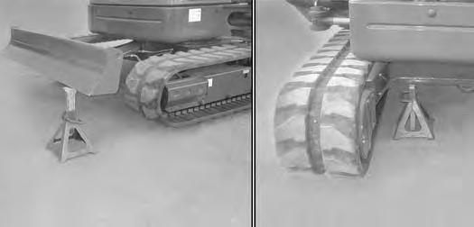
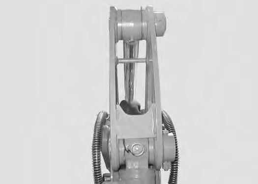
Raise one side of the machine (approximately 101,6 mm [4 in]) using the boom and arm [Figure194]
Figure195
Raise the blade fully and install jackstands under the blade and track frame (Item 1) [Figure195]. Lower the boom until all machine weight is on the jackstands.
Stop the engine.
Measure the clearance at the middle track roller. Do not get fingers into pinch points between the track and the track roller. Use a bolt or a dowel of the appropriate size to check the gap between the contact edge of the roller and the top edge of the track guide [Figure196] and [Figure197]
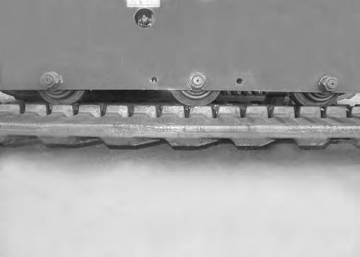
Rubber Track Clearance - 10 - 15 mm (0.39 - 0.59 in).
TRACK TENSION (CONT’D)
Adjusting (Cont’d)
Steel Track Clearance
Figure198
Measure the track clearance “A” at the middle track roller. Do not get fingers into pinch points between the track and the track roller. Check the gap between the bottom edge of the track frame and the top surface of the track [Figure198]
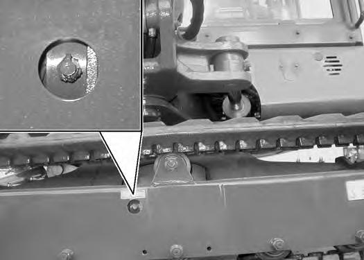
NOTE:The track tension grease fitting (Item 1) is installed into the end of the bleed fitting (Item 2). DO NOT loosen the grease fitting (Item 1), loosen the bleed fitting (Item 2) [Figure199] ONLY (maximum of 1-1/2 turns) when releasing track pressure.
Add grease to the fitting (Item 1) [Figure199] until the track tension is correct.
To release track pressure, loosen the bleed fitting (Item 2) [Figure199] to release tension from the track.
NOTE: Do not loosen the grease fitting (Item 1) [Figure199].
Repeat the procedure for the other side.
HIGH PRESSURE GREASE CAN CAUSE SERIOUS INJURY
•Do not loosen grease fitting.
•Do not loosen bleed fitting more than 1 - 1/2 turns.
Travel Motor
Checking And Adding Oil
Figure200
Park the excavator on a level surface with the plugs (Item 1, 2 and 3) [Figure200] in the position as shown.
Remove the plug (Item 1) [Figure200]. The lube level must be at the bottom edge of the hole.
Add lubricant (80W-90) through hole (Item 2) [Figure200] if the lube level is low. (See REGULAR MAINTENANCE ITEMS on Page 9.)
Removing And Replacing Oil
For the correct service interval (See SERVICE SCHEDULE on Page 95.)
Park the excavator on a level surface with plugs (Item 1, 2 and 3) in the position shown. Remove plugs (Item 2 and 3) [Figure200] and drain the lubricant into a container.
Warning
AVOID INJURY OR DEATH
Always clean up spilled fuel or oil. Keep heat, flames, sparks or lighted tobacco away from fuel and oil. Failure to use care around combustibles can cause explosion or fire.
W-2103-0508
Install the bottom plug (Item 3). Add lubricant through the top plug (Item 2) until the lube level is at the bottom edge of the plug hole (Item 1) [Figure200]. (See REGULAR MAINTENANCE ITEMS on Page 9.)
Install the plugs (Item 1 and 2) [Figure200]
Repeat the procedure for the opposite travel motor.
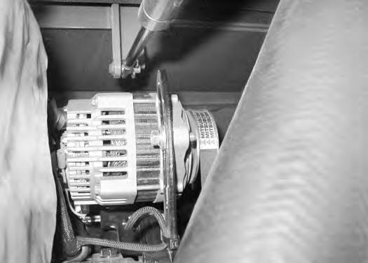
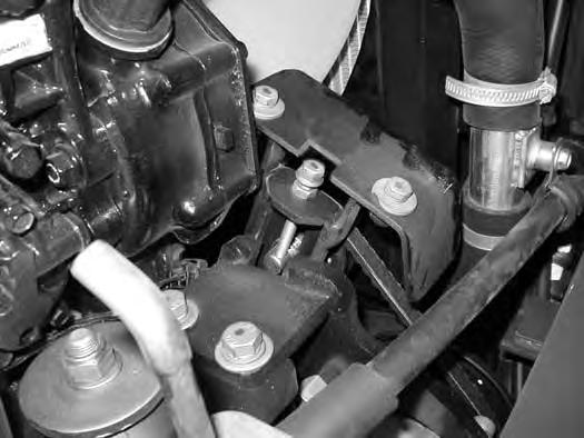
Alternator Belt
Belt Adjustment
See the SERVICE SCHEDULE for the correct service interval. (See SERVICE SCHEDULE on Page 95.)
Open the right side cover. (See RIGHT SIDE COVER on Page 100.)
Belt Replacement
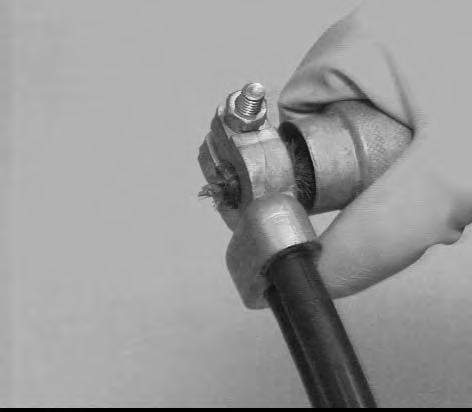
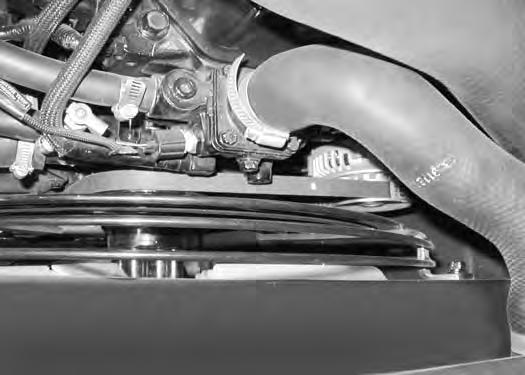
Loosen the alternator mounting bolt (located below the alternator). Loosen the bolt (Item 1) [Figure201]
Loosen the alternator mounting bolt (located below the alternator). Loosen the bolt (Item 1) [Figure203]. Remove the old belt and install a new belt.
When belt tension is correct, tighten the alternator bolts.
Warning
AVOID INJURY OR DEATH
•Do Not Operate with damaged or missing screens, shields or rubber deflectors.
•Stop engine before cleaning or servicing.
•Contact with moving parts or flying objects can cause injury or death.
Press down on the belt midway between the fan pulley and the alternator pulley. The correct tension should allow the belt to deflect 10 mm (0.375 in) [Figure202]
When belt tension is correct, tighten the alternator bolts.
Air Conditioning Belt
Belt Adjustment
See the SERVICE SCHEDULE for the correct service interval. (See SERVICE SCHEDULE on Page 95.)
Open the right side cover. (See RIGHT SIDE COVER on Page 100.)
The air conditioning belt will be adjusted using the bolt (Item 1) [Figure204]
Press down on the belt midway between the crankshaft pulley and the compressor pulley. The correct tension should allow the belt to deflect 10 mm (0.375 in) [Figure206].
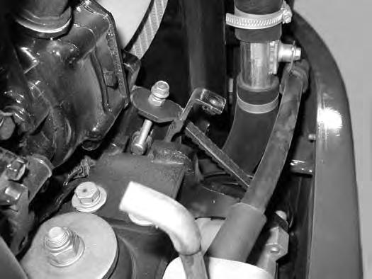
Loosen the lock nut (Item 1) and adjust the bolt (Item 2) [Figure206] until the belt tension is correct.
When belt tension is correct, tighten the lock nut (Item 1) [Figure206]
Tighten the belt idler mounting bolt (Item 1) [Figure205].
Reinstall the shield (Item 2) and the two bolts and washers (Item 3) [Figure204]
Warning
AVOID INJURY OR DEATH
•Do Not Operate with damaged or missing screens, shields or rubber deflectors.
•Stop engine before cleaning or servicing.
•Contact with moving parts or flying objects can cause injury or death.
W-2528-0406
NOTE:Belt shield removed for photo clarity in the following two photos.
Loosen the belt idler mounting bolt (Item 1) [Figure205]
AIR CONDITIONING BELT (CONT’D)
Belt Replacement
Figure207
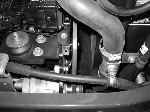
Remove the two bolts and washers (Item 1) and remove the shield (Item 2) [Figure207]
Loosen the lock nut (Item 1) and the bolt (Item 2) [Figure209] until the belt can be removed.
Install a new belt.
Adjust the bolt (Item 2) until the belt tension is correct. Tighten the lock nut (Item 1) [Figure209]
Tighten the belt idler mounting bolt (Item 1) [Figure208]
Reinstall the shield (Item 2) and the two bolts and washers (Item 1) [Figure207].
Warning
AVOID INJURY OR DEATH
•Do Not Operate with damaged or missing screens, shields or rubber deflectors.
•Stop engine before cleaning or servicing.
•Contact with moving parts or flying objects can cause injury or death.
Loosen the belt idler mounting bolt (Item 1) [Figure208]
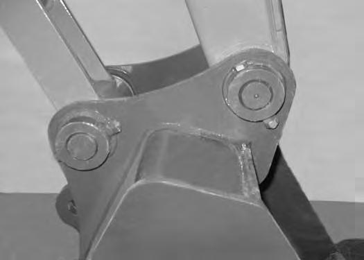
Attachment
Pin-On Inspection And Maintenance
Figure210
Inspect the bucket pins (Item 1) and hardware (Item 2) [Figure210] for wear or damage. Inspect the bucket (on the attachment) for wear or damage.
Repair or replace damaged parts.
Quick Coupler And Attachment Inspection And Maintenance
Inspect the four O-ring seals (Item 1) [Figure211] for wear or damage.
Repair or replace damaged or missing parts.

Inspect the quick coupler for wear or damage. Inspect the quick coupler pins (Item 1) and the hooks (Item 2) [Figure212] (on the attachment) for wear or damage.
Repair or replace damaged parts.
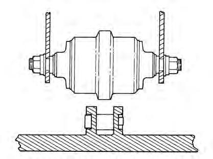
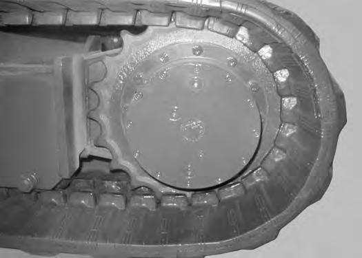
Track Roller And Idler Lubrication
Procedure
The track rollers and idlers require no maintenance. The bearings are a sealed design.
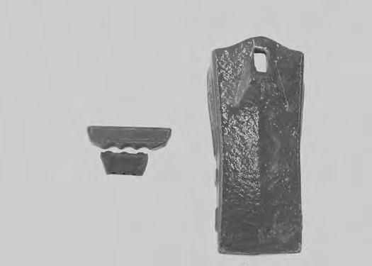
Bucket Teeth Removal And Installation
Pin-On Buckets
Warning
Wear safety glasses to prevent eye injury when any of the following conditions exist:
•Pressurised fluids and springs or other stored energy components.
•Flying debris or loose material is present.
•Engine is running.
•Tools are being used.
W-2505-EN-1009
Position the bucket so the bucket teeth are at a 30° angle up from the ground for accessibility to the teeth. Install a block under the bucket.
Lower the boom until the bucket is fully on the ground and resting on the block.
Stop the engine and exit the excavator.
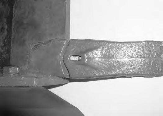
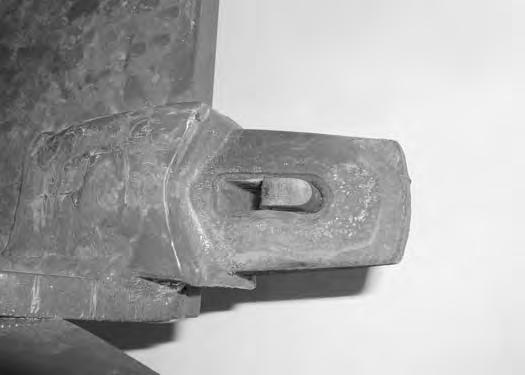
Removal: Use a punch and a hammer and drive the retainer pin (Item 1) down and out the bottom of the tooth (Item 2) [Figure214]. Remove the tooth from the shank.
The bucket tooth (Item 1) has a unique retaining pin (Item 2) and rubber retainer (Item 3). The retaining pin (Item 2) must be installed as shown with the notch towards the rubber retainer (Item 3). The rubber retainer (Item 3) [Figure213] will be installed into the shank before the tooth is installed on the shank.
Remove the rubber retainer (Item 1) from the shank (Item 2) [Figure215]
Installation: Install the rubber retainer (Item 1) into the tooth shank (Item 2) [Figure215]
Position the new tooth point (Item 2) [Figure214] on the shank (Item 2) [Figure215]
Install the retainer pin (Item 1) [Figure215] until it is flush with the top of the tooth.
Lubricating The Excavator
Lubrication Locations
Lubricate the excavator as specified in the SERVICE SCHEDULE for the best performance of the machine. (See SERVICE SCHEDULE on Page 95.)
Record the operating hours each time you lubricate the excavator.
Always use a good quality lithium based multipurpose grease when lubricating the machine. Apply the lubricant until extra grease shows.
Ref
LUBRICATING THE EXCAVATOR (CONT’D)


Lubrication Locations (Cont’d)
LUBRICATING THE EXCAVATOR (CONT’D)
Lubrication Locations (Cont’d)
Figure223
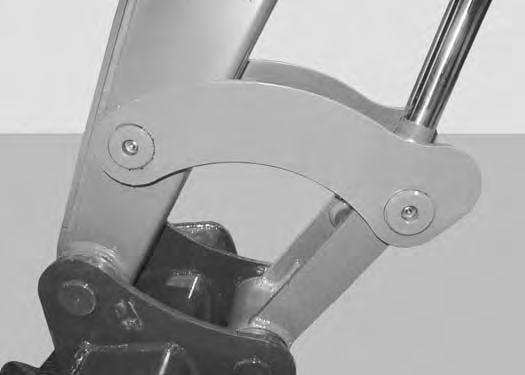
11.Arm Cylinder Rod End (1).
12.Bucket Cylinder Base End (1) [Figure223]
15.Link Pivot Pin (2).
16.Arm (1) [Figure225]
13.Bucket Cylinder Rod End (1).
14.Bucket Link (1) [Figure224].
Lubricate the following locations on the hydraulic Excavator:
17.Boom Swing Cylinder Base End (1).
18.Slew Circle (1).
19.Slew Pinion (1) [Figure226]. (Install 3 - 4 pumps of grease then rotate the upperstructure 90°. Install 3 - 4 pumps of grease and again rotate the upperstructure 90°. Repeat this until the slew pinion has been greased at four positions.)