ALTERNATOR CHARGE SYSTEM (500, 600) Rectifiers and stators on Kohler and Wisconsin engines are often needlessly replaced. The electrical system fuse is in the positive battery cable circuit, which carries both charge and draw amperage. A burned out fuse, corrosion in the fuse holder or an otherwise poor connection would create a no charge condition. Check the condition of the fuse and its contacts within the holder before assuming more serious alternator problems.
To check the stator: Examine leads for broken wires or loose connections. If none is found, remove one red and one black lead from RECTIFIER–REGULA TOR. Using an ohmmeter with R x 1 scale (Simpson Model 260, or similar meter with ohmmeter sensitivity of 20,000 ohms/volt) check continuity as follows: (See Chart at Right.) METER PROBE CONNECTIONS
Use the following procedures only when battery is not fully charged. Determine charge with hydrometer. It should not exceed 1225. (See Chart, Below Right.)
The metallic portions ofthe regulator are isolated from the mounting, and so the same regulator can be used in either a positive or negative ground system. WISCONSIN and KOHLER MOTORS, however, have adapted negative grounds as standard for all 12 volt generating circuits. All alternator–regulator wiring furnished by WISCONSIN and KOHLER will be for negative ground, and wired in accordance with the diagram in figure 43. The white wire attached to the BAT–NEG terminal on the rectifier–regulator is grounded to the engine at a lug under one of the starter mounting bolts. This lug is also used for attaching the ground cable from the negative post of the battery to the engine.
2.0 Ohms ° Indicates Short Circuit 0.1 Ohms ∞ Indicates Open Circuit
Red to Red Black to Black
Red to Black Red to Engine Black to Engine
Alternator wiring:
CORRECT REPLACE METER VALUE STATOR
∞ ∞ ∞
Any Reading Indicates Short Circuit
RESISTANCE CHART
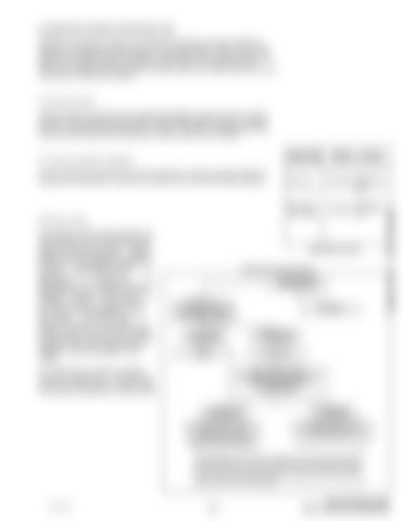
PROBLEM ANALYSIS CHART ENGINE STOPPED READ AMMETER
INDICATOR AT 0 DISCHARGE
START ENGINE AND RUN AT NORMAL SPEED OVER 5 AMPS ON AMMETER
5 AMPS OR LESS ON AMMETER
NORMAL
STOP ENGINE
All leads from the rectifier–regulator must be 10 gauge wire and shall not exceed 10 feet in length. If longer leads are needed, 8 gauge wire must be used.
Dealer Copy -- Not for Resale
To check the Rectifier–Regulator:
DISCONNECT BATTERY Disconnect red wire from REG terminal on Rectifier – Regulator and tape it. RECONNECT BATTERY START ENGINE
5 AMPS OR aLESS ON AMMETER
20 TO 30 AMPS ON AMMETER
RECTIFIER section of Rectifier Regulator inoperative
REGULATOR section of Rectifier Regulator inoperative
Replace Rectifier–Regulator
FOR EMERGENCY USE: Operate with REG wire disconnected and taped (to prevent short). After 1 hour, connect loose red wire to AC terminal. Charge will be 5 amps. After additional operation, if battery required more charge remove red wire from AC and repeat.
27 of 102
–15–
444, 500, 600 Loader Service Manual Supplement
