39 minute read
ELECTRICAL SYSTEM


ALTERNATOR CHARGE SYSTEM (500, 600)
Rectifiers and stators on Kohler and Wisconsin engines are often needlessly replaced. The electrical system fuse is in the positive battery cable circuit, which carries both charge and draw amperage. A burned out fuse, corrosion in the fuse holder or an otherwise poor connection would create a no charge condition. Check the condition of the fuse and its contacts within the holder before assuming more serious alternator problems.
To check the stator:
Examine leads for broken wires or loose connections. If none is found, remove one red and one black lead from RECTIFIER–REGULATOR. Using an ohmmeter with R x 1 scale (Simpson Model 260, or similar meter with ohmmeter sensitivity of 20,000 ohms/volt) check continuity as follows: (See Chart at Right.)
To check the Rectifier–Regulator:
Use the following procedures only when battery is not fully charged. Determine charge with hydrometer. It should not exceed 1225. (See Chart, Below Right.)
Red to Red Black to Black
Red to Black Red to Engine Black to Engine
Alternator wiring:
The metallic portions ofthe regulator are isolated from the mounting, and so the same regulator can be used in either a positive or negative ground system. WISCONSIN and KOHLER MOTORS, however, have adapted negative grounds as standard for all 12 volt generating circuits. All alternator–regulator wiring furnished by WISCONSIN and KOHLER will be for negative ground, and wired in accordance with the diagram in figure 43. The white wire attached to the BAT–NEG terminal on the rectifier–regulator is grounded to the engine at a lug under one of the starter mounting bolts. This lug is also used for attaching the ground cable from the negative post of the battery to the engine.
All leads from the rectifier–regulator must be 10 gauge wire and shall not exceed 10 feet in length. If longer leads are needed, 8 gauge wire must be used.
INDICATOR AT 0
START ENGINE AND RUN AT NORMAL SPEED
OVER 5 AMPS ON AMMETER
NORMAL
PROBLEM ANALYSIS CHART
ENGINE STOPPED READ AMMETER
5 AMPS OR LESS ON AMMETER
DISCONNECT BATTERY Disconnect red wire from REG terminal on Rectifier – Regulator and tape it.
RECONNECT BATTERY START ENGINE
° ∞
Any Reading
∞ Indicates Short ∞ Circuit
5 AMPS OR LESS ON AMMETER a 20 TO 30 AMPS ON AMMETER
RECTIFIER section of Rectifier Regulator inoperative
Replace Rectifier–Regulator
REGULATOR section of Rectifier Regulator inoperative
FOR EMERGENCY USE: Operate with REG wire disconnected and taped (to prevent short). After 1 hour, connect loose red wire to AC terminal. Charge will be 5 amps. After additional operation, if battery required more charge remove red wire from AC and repeat.
Installation of Equipment Solenoids:
1.Do not connect solenoid power lead to rectifier–regulator BAT–NEG terminal.
2.Make power lead connection at starter switch (as close to battery as possible) (Fig. 43).
3.Add by–pass condenser at solenoid terminal. Use a 1 MFD condenser similar to that used for auto radio suppression.
Rectifier–Regulator Mounting:
The rectifier–regulator is insensitive to vibration and thus can be mounted to any type of support. Installation must, however, be in a vertical position. This chimney effect mounting tends to dissipate heat more efficiently. The four lead wires from the stator are 36” long, and if it is desired to mount the rectifier–regulator at some location other than the standard position on the engine shroud, approximately 15 inches of wire is available for this purpose.
Because an alternator differs from a D.C. generator, there are precautions to take:
1.Do not reverse battery connections.
2.Connect booster batteries properly; positive to positive and negative to negative.
3.Disconnect the regulator to battery lead if a fast charger is used.
4.Never use a fast charger to boost battery output.
5.Do not attempt to polarize the alternator. It needs no polarization.
6.Do not ground output wires or field wires between the alternator and regulator.
7.When arc welding on machine, disconnect battery ground lead.
8.Do not operate engine with battery disconnected from system.
Flywheel Alternator System:
The alternator system used on the K662 Kohler and VF4D Wisconsin engines provides electrical power to charge the 12 volt battery and also furnishes power for a lighting circuit. This system has the following basic components:
1.Permanent Field Magnet Ring.
2.Alternator Stator.
3.Full Wave Rectifier.
4.Voltage Regulator.
A brief description of each of these components willaid in explaining the operation of this system:
1.Permanent Magnet Ring: This assembly consists of 12 permanent magnets imbedded in a die cast ring. The ring is affixed to the inside rim of the flywheel, then machined to obtain the proper air gap between it and the stator.
2.Alternator Stator: The stator is assembled in stationary positionon the gear housing of the engine. This assembly consists of twelve coils. Each of the coils contain a primary or load winding and a secondary winding which acts as a regulatory winding.
3.Full Wave Rectifier: A rectifier is a device used to convert alternating current to direct current. The rectifier used does this through the use of half–wave diodes. These are electronic devices that allow current to flow in one direction but block flow in opposite direction. Since alternating current continually alternates from positive to negative direction the use of both positive negative diodes in a full wave bridge arrangement rectify AC into a smooth flow of direct current. Since excessive heat will effect the operation of this rectifier, the heat dissipating fins must be mounted in an upright position for maximum cooling.
4.Voltage Regulator: This is a solid state regulator that uses resistors, a silicon controlled rectifier (SCR) and a Zener voltage sensor. The use of solid state electronic devices eliminates the necessity of mechanically operated contacts and thus failure due to vibratory damage or fatigue. The voltage regulating device is mounted on the front of the full wave rectifier.
5.Function of the Alternator System: As the field magnet ring rotates around the stator, and alternating current is induced in the primary or load winding of the stator, the current produced is approximately 35 amperes. This AC currents flows to the Full Wave Rectifier where it is rectified to direct current which then flows to the battery and lighting circuit.
The regulator acts to limit the battery charge rate by controlling battery voltage. When the Zener diode in the voltage regulator senses capacity charging, it switches and allows current to flow into the secondary winding of the stator. As current flow increases in the secondary, it causes the current flowing in the primary winding to decrease. When no current flows in the secondary, maximum current flows in the primary, likewise, when no power is needed in the load winding, maximum current flows in the regulator winding.
Servicing the Alternator System:
The serviceman will find that the syncro alternator differs somewhat from the conventional alternator or generator. The conventional alternator must derive output current through the use of a field current from the battery, whereas the syncro alternator has current available at all times and uses it only to regulate voltage. This is accomplished through the use of an electronic switch known as a silicon controlled rectifier. When the SCR conducts regulating current through the regulating winding, it actually limits or turns off the current flow in the load winding as the current demand varies.
1.Installation of Rectifier–Regulator Assembly. Assembly must be installed in a vertical position, creating a chimney effect which tends to dissipate heat more efficiently.
Do NOT install resistors, fuses or lead wire smaller than No. 10 AWG in connections from the battery to the bridge rectifier assembly.
2.Service Procedure: It is desirable to check an improperly operating alternator with a volt ohmmeter. Listed below are various alternator problems with a detailed analysis of best procedure to follow: a.First examine lead wires for loose or broken connections at the rectifier–regulator. Opens or ground may be detected in the stator through the use of the R x 1 scaleof your ohmmeter. Remove four input leads from rectifier–regulator. Connect meter test leads to read lead wires to check continuity. Approximately 2,0 ohms resistance should be read on your ohmmeter. b.Full Wave Bridge Rectifier: Examine each of four diodes for breakdown by connecting ohmmeter R x 1 scale from AC input connection to positive plate, then move lead to negative plate alternately. Meter should read approximately 10 ohms in proper polarity. A shorted diode will indicate no resistance and would cause a short circuit through the load winding when in operation. An open diode would read infiniteresistance and would also indicate that replacement is necessary. c.Regulator Assembly: The regulator assembly contains two semiconductors, a silicon controlled rectifier, which is the electronic switch for the control winding, and a zener diode which is the battery voltage sending device, turning the SCR on when the battery voltage at the predetermined level. To adjust voltage, remove two screws from regulator cover, lift cover off, connect voltmeter to battery terminals. Be sure the battery load is less than alternator output so that unit is regulating. With alternator running at approximately one–half speed, adjust potentiometer to desired voltage (Fig. 44). d.Battery Voltage Too Low: Follow previous procedure, turning variable resistor clockwise. e.Full Charge Will Not Regulate: Check for broken lead wires at connection to regulator plates. To be sure regulator winding operates properly, connect two red leads together. Start engine. A Maximum of four amperes charge should be noted. This would indicate stator winding is satisfactory. Regulator should be replaced. f.Battery Voltage Too High: Remove regulatory cover. Connect voltmeter to battery terminals. Start engine. With a small screwdriver or suitable blade adjust variable resistor counterclockwise until proper voltage is obtained. Replace cover.
Next connect meter to black lead wires. Approximately 0.1 ohms should be your reading here. There should be no ground connections from either winding, nor should there be a connection between windings. If a connection exists between the two windings or to ground, stator assembly should be replaced.
Turn Clockwise To Increase
TURN COUNTERCLOCKWISE TO REDUCE g.No Charge: If alternator does not charge when load is applied to battery, shut off engine. Disconnect regulator lead (red) from regulator terminal. Be surelead is taped or isolated from conducting engine parts. Once again start engine. Alternator should charge to full output. If not assembly should be replaced.
Current rectifiers furnished by the engine manufacturer do not have the voltage adjustment feature. This was eliminated to improve the service life of the unit.
NOTE: Read this completely before attempting any checks.
VF4D Wisconsin engines have the rectifier and regulator modules mounted to the shrouding at the rear of the engine. On some engines the rectifier and regulator modules were mounted behind the distributor. They are hard to check and service. You may want to move the modules out onto the shrouding. To do this (Fig. 45):
1.Disconnect the connectors by squeezing the outer ends of the receptacles and pulling apart.
2.Remove the modules from their position behind the distributor.
3.Mount the modules on the shroud at the rear of the engine. Mount the rectifier slightly higher and to the left of the regulator module.
NOTE: The rectifier and regulator modules are grounded to the engine frame. You will need to remove paint from the shroud to get a metal to metal contact between the base of the modules and the shrouding. Do not mount the modules anywhere other than on the engine.
4.Use a jumper harness (Fig. 46, Item 1) to connect the stator leads to the rectifier and regulator modules. The fool–proof type connectors prevent incorrect wiring.
Checking The Rectifier And Regulator
All ohmmeter readings are to be made on the R1 scale. Examine the leads for broken or frayed wires, or loose connections. If none are found, disconnect the battery and uncouple the rectifier and regulator modules from the jumper harness. Make sure the bases of the modules are making good contact with the engine shroud. Use an ohmmeter to check whether the rectifier and regulator are defective. All the checks can be completed without removing anything from the machine. If a meter connection is shown going to ground, it means engine ground. Be sure you have a good ground connection.
NOTE: If your ohmmeter does not give you the readings shown in figures 47 thru 56, reverse the leads going into your meter. If the readings still differ from the readings listed, replace the part tested.
Stator Checks
Use a test light (or continuity tester) to check for shorts from the stator leads to ground. The test light will indicate any shorts by lighting the bulb. If the bulb indicates there is a short, the stator will need to be replaced. If the bulb does not light when checking any of the statorleads to ground, check to make sure there is continuity (bulb lights) between each combination of two stator leads. If you have continuity, go on to the voltage check. Use a voltmeter to check the stator. Run the engine at full throttle when taking these readings.
NOTE: The voltmeter readings may differ from the ones shown in figures 57 thru 61. The readings given are meant as a guide.
If the stator is bad, the readings will differ greatly from the readings shown. They will be lower readings.
NOTE: If the engine is not run at full RPM the readings may vary.
If all checks are made and all readings are acceptable, but the battery doesn’t charge, there must be a bad connection in the wiring harness or the battery terminal.
NOTE: The blue wire, as referred to in these tests, is thewire next to the red wire. It is blue coming off the stator, but may be any color next to the connector.
Any reading indicates a short circuit
Any reading indicates a short circuit
WISCONSIN ENGINE SERVICE (M–600)
Restoring Compression
On a new engine or on one which has been out of operation for some time, the oil may have drained off the cylinders so that compression will be weak. This may cause difficulty in starting. To remedy this condition, remove the spark plug and pour about a fluid ounce of engine oil through the spark plug hole into each cylinder.
Turn the engine over several times by hand to distribute the oil over the cylinder walls. Then replace the spark plug and compression should be satisfactory.
Governor Adjustment
The control rod between the governor and carburetor must be adjusted to the proper length, or the governor action will be faulty. With the engine at rest, the governor spring will hold the flyweights in, and the control rod must be of such length as to hold the carburetor throttle wide open at this point. The accuracy of this adjustment can be tested by disconnecting the control rod from the governor lever, then pushing the rod toward the carburetor as far as it will go. This will open the throttle wide. The governor lever should then be moved as far as possible in the same direction; all of this being donewith the rod disconnected from the lever. Holding both parts in the above position, the rod should be screwed into the swivel block on the carburetor, until the bent end of the rod will register with the hole in the lever.
Then, screw the rod in two more turns. Insert the rod into the hole in the governor lever and insert the cotter pin. With the governor lever pushed toward the carburetor as far as it will go, there should be about 0.0625 inch clearance between the throttle lever and the stop pin on the carburetor. The clearance will cause the lever to bounce back from the stop pin, rather than jam against the pin, when a load is suddenly applied to the idling engine.
The governor lever is furnished with 12 holes (Fig. 66) for attaching the governor spring. For operation in a Bobcat using model VF4 Wisconsin engine, the spring should be hooked into the No.10 hole in the arm. This would set the enginespeed to 2400 RPM under load. For Bobcats using model VH4 Wisconsin engine, the No. 12 hole should be used. This would set the engine speed to 2800 RPM under load (Fig.67).
Storage Of Engines
Clean the exterior of the engine completely
To protect the cylinders, pistons, rings and valves from rusting and sticking, a half and half mixture of kerosene and engine oil should be injected into the pipe tap opening on the intake manifold while the engine is warm and running at moderate speed. About a quarter pint is necessary, or enough so a heavy bluish smoke will appear at the exhaust. Shut the engine off. The fogging operation will give a coating of oil on the above mentioned parts, protecting them from the atmosphere.
Drain the oil from the crankcase.
Drain the fuel system.
Returning Stored Engine To Service
Drain condensation from the engine.
Fill the crankcase to the proper level with the proper grade of engine oil. Check the spark plugs. Refuel the engine.
Carburetor Adjustment
The main metering jet in the carburetor is of the fixed type. It requires no adjustment. The idle needle should be adjusted for best low–speed operation, while the carburetor throttle is closed by hand. Turning the needle in closer to its seat results in a richer mixture. Turning the needle out away from its seat results in a leaner mixture (Fig. 68).
CARBURETOR RECONDITIONING (Fig.
69)
To remove the throttle body assembly:
1.Remove the four bowl to body assembly screws (Item 35) and lockwashers using a screwdriver.
2.Raise the throttle body slightly and separate the bowl to body gasket (Item 17) from the fuel bowl assembly, then lift off the throttle body carefully to avoid damage to the floats.
To disassemble the throttle body:
1.Press against the end of the float axle (Item 16) at the slotted side of the hinge bracket to force the axle through the hinge bracket. Use a small screwdriver. Then remove the float axle from the opposite side. Remove the float assembly (Item 15) and fuel valve needle.
2.Remove the bowl to body gasket (Item 17) from the machined surface of the throttle body (Item 8) then remove the venturi (Item 18).
3.Remove the fuel valve seat (Item 14) with its fiber washer (Item 13).
4.Remove the idle adjusting needle (Item 10) and friction spring (Item 9) from the side of the throttle body 5.
5.Remove the idle jet (Item 11) from the passage in the machined surface of the throttle body, near the fuel valve seat. Use a small screwdriver.
6.Back out the throttle stop screw (Item 2) flush with the end of the lever (Item 3). Close the throttle and mark the levers and throttle body as a guide to correct assembly of parts.
NOTE: Do not remove the throttle plate, throttle shaft and lever assembly, throttle packings and retainers from the throttle body unless the shaft is bent or other components of the assembly are damaged.
7.File off the riveted or peened ends of the throttle plate screws (Item 4) flush with the throttle shaft. Use care not to damage the throttle plate or throttle bore.
8.Remove the throttle plate screws, throttle plate (Item 6) and throttle shaftand lever assembly (Item 3).
9.To remove the throttle shaft packing and retainer (Item 5), screw a 0.3125 inch – 24 thread tap into the packing retainer until firmly seated. Insert a long punch or rod through the opposite shaft hole and drive out the retainer and packing. Repeat for the other side.
10.Remove the fuel inlet plug (Item 12) and screen (if used).
To disassemble the fuel bowl:
1.Remove the 0.500 inch plug (Item 34) from the bottom of the fuel bowl. Remove the fiber washer (Item 33).
2.Remove the fuel bowl drain plug (Item 12) from the bottom of the bowl.
3.Remove the main jet (Item 32) and fiber washer (Item 31)from the threaded passage near the bottom of the fuel bowl.
4.Remove the main discharge jet (Item 40) with its fiber washer (Item 39) from the center of the fuel bowl casting.
5.Remove the well vent jet (Item 19) from the machined surface of the fuel bowl. Use a small screwdriver.
6.Mark the choke bracket (Item 22), choke lever (Item 29) and air intake body as a guide to correct assembly.
7.Remove the choke lever spring (Item 25). Close the choke and remove the choke plate screws (Item 4) and choke plate (Item 38). Note the position of the poppet spring in the air intake.
8.Remove the choke shaft nut (Item 26) and lockwasher (Item 27). Remove the choke lever (Item 29).
9.Remove the bracket assembly screw (Item 30) using 0.500 inch open end wrench. Remove the choke bracket (Item 22).
10.Remove the choke shaft hole plug (Item 34) and fiber washer (Item 33) using a 0.500 inch open end wrench.
NOTE: For removal of choke shaft packings and retainers, refer to step 9 under disassembling the throttle body.
Thoroughly clean all metal parts, using a special carburetor parts cleaner and rinse in solvent. Blow out all passages and channels in the castings with compressed air. Reverse the air flow through each passage toinsure the removal of all dirt particles.
Never use a wire or drill to clean out the jets. WARNING
Inspect all parts and replace any that are damaged orworn. Always use a repair kit. For the correct repair kit to use, see your Bobcat Parts Book.
To reassemble the fuel bowl and air intake assembly:
1.Insert the choke shaft packing and retainer using a bushing driver. Be careful. Lightly drive the retainer into the body until flush with the machined surface. Repeat for opposite side.
2.Carefully guide the choke shaft (Item 20), through the packings and retainers, into position in the air intake body. Insert the choke plate (Item 38) into the cut out of the choke shaft. Make sure the choke plate poppet valve is in the same position as when it wasdisassembled. Install the choke plate screws using a small screwdriver.
3.Install the choke shaft hole plug (Item 34) with its fiber washer (Item 33) and tighten with a 0.500 inch open end wrench.
4.Place the choke shaft bracket (Item 22) on the assembly screw (Item 30) and attach the bracket to the air intake in the same position as when removed. Tighten the screw using a 0.500 inch wrench.
5.Assemble the choke lever (Item 29) onto the choke shaft in the sameposition as when removed, using the lockwasher (Item 27) and nut (Item 26). Tighten the nut.
6.Attach the choke lever spring (Item 25) to the choke lever and choke bracket.
7.Place the fiber washer (Item 39) over the threads of the main discharge jet (Item 40). Install the main discharge jet in the bowl assembly and tighten firmly.
8.Install the well vent jet (Item 19) in the bowl assembly. Tighten using a small screwdriver.
9.Place the fiber washer (Item 31) on the main jet (Item 32) and install the main jet in the threaded hole near the bottom of the bowl.
10.Install the hex plug (Item 34) and gasket (Item 33) and tighten securely.
To reassemble the throttle body assembly:
1.Insert the throttle shaft packing and retainer using a bushing driver. Be careful. Lightly drive the retainer into the body until flush with the machined surface. Repeat for other side.
2.Insert the throttle shaft and lever assembly (Item 3) into the throttle body. Rotate the shaft to wide open position.
3.Insert the throttle plate (Item 6) and rotate to closed position. Hold the plate with your fingers and start the throttle plate screws (Item 4). Partially tighten them with a small screwdriver. Center the throttle plate in the throttle bore and tighten the screws.
NOTE: Make sure the beveled edges of the throttle plate fit the throttle bore when the throttle plate is closed.
4.Install the idle adjusting needle (Item 10) and friction spring (Item 9) into the threaded passage at the side of the throttle body. Turn the needle IN lightly against its seat. Then, back the OUT 1–1/4 turns as a preliminary adjustment.
5.Install the idle jet (Item 11) in its counter–bored passage and tighten, using a small screwdriver.
6.Install the fuel inlet plug (Item 12) and screen (if used) in the threaded hole at the throttle body.
7.Invert the throttle body and install the fuel valve seat (Item 14) and fiber washer (Item 13).
8.Place a new throttle body to fuel bowl gasket (Item 17) on the machined surface of the fuel bowl cover. Install the fuel valve needle (Item 14) in its seat.
9.Place the float assembly (Item 15) in position with the float lever bushing in line with the holes in the hinge bracket. Install the float axle (Item 16).
10.To insure correct fuel level in the float chamber, check distance (Fig. 70) from the top of the floats to the machined surface of the cover. To change the distance, use a long–nosed plier and bend the lever close to the float body.
Do not bend, twist or put pressure to the float bodies. When seen from their free end, the float bodies must be centered and at right angles to the machined surface and must move freely on the float axle. I–2150–1297
11.Insert the large opening end of the venturi (Item 18) into the throttle bore and position the venturi so the machined flat will be toward the fuel bowl when the bowl is assembled.
To reassemble the throttle body assembly:
1.Place the fuel bowl assembly on the throttle body assembly and align the holes in the bowl flange with the holes in the gasket and cover.
2.Install the four assembly screws (Item 35). Tighten them evenly and securely.
3.Hold the throttle lever in closed position and turn the throttle stop screw (Item 2) IN until it contacts the stop pin on the throttle body. Turn the screw IN 1–1/2 additional turns as a preliminary adjustment.
Lpg Carburetor Service
To disassemble the carburetor:
1.Mark the throttle plate (Fig. 71, Item 6) and main body for correct reassembly of the throttle plate. Remove the throttle plate screws (Item 5) and throttle plate.
2.Remove the throttle shaft and lever assembly (Item 10).
3.Remove the shaft seals (Item 3) and seal retainers (Item 2) from both sides of the main body.
4.Remove the venturi retaining screw (Item 11) and remove the venturi (Item 4) from the main body.
5.Remove the idle needle valve (Item 8) and idle needle valve spring (Item 9) from the main body.
6.Invert the carburetor, loosen the adjusting nut (Item 12) and remove the main adjusting screw (Item 13) with the adjusting nut.
7.Remove the screw plug (Item 21).
8.Mark the choke plate (Item 22) and air intake for correct reassembly of the choke plate. Remove the choke plate screws (Item 5) and choke plate. Remove the choke shaft nut (Item 16), choke lever (Item 15), choke shaft plug (Item 25) and choke shaft (Item 23).
9.Mark the location of the choke cable bracket (Item 19). Remove the choke bracket screw (Item 14).
Thoroughly clean all metal parts, using aspecial carburetor parts cleaner. Rinse in solvent. Blow out all passages and channels in the casting with compressed air. Reverse the air flow through each passage to insure the removal of all dirt particles.
Warning
To reassemble the carburetor:
Never use a wire or drill to clean out the jets. Inspect all parts and replace any that are damaged or worn.
1.Attach the choke cable bracket (Item 19) to the main body using the bracket screw (Item 14) position as marked at time of disassembly and securely tighten the screw.
2.Insert the choke shaft (Item 23) and choke shaft hole plug (Item 25), attach the choke plate (Item 22) to the choke shaft. Position the choke plate as marked at time of disassembly. Leave the screws loose. Closethe choke and align for best closing, then securely tighten the screws.
3.Attach the choke shaft lever (Item 15) to the choke shaft with its hex nut (Item 16). Position the lever as marked at time of disassembly. Securely tighten the nut.
4.With the carburetor inverted, replace the pipe plug (Item 21), adjustment screw locknut (Item 12) and adjustment screw (Item 13). Turn the adjustment screw in against its seat, then back it out two turns.
5.With the flange of the carburetor up, place the venturi (Item 4) into the throttle bore with the side hole in line with the screw hole in the main body and secure the venturi with its retaining screw (Item 11).
6.Place the throttle shaft seals (Item 3) into the seal retainers (Item 2) and assemble the seals and retainers into the counterbores of the main body.
7.Insert the throttle shaft and lever (Item 10) through the seals so the throttle stop screw is in contact with the stop pin when the throttle plate is in closed position. Attach the throttle plate (Item 6) to the shaft. Leave the screws loose. Align the throttle plate to the match marks. Close the throttle and align the plate for best closing. Tighten the screws.
8.Place the spring on the idle needle valve (Item 8) and install the idle needle and spring. Turn the needle valve in lightly against its seat. Back out the needle valve 1–1/4 turns.
VAPORIZER – PRIMARY REGULATOR SERVICE
The vaporizer (Fig. 72) consists of a high pressure regulator and vaporizer combined into a single unit. The high pressure regulator reduces LPG fuel tank pressure to a uniform outlet pressure. The vaporizer section vaporizes the liquid gas.
To disassemble the vaporizer:
Refer to figure 73 for parts identification and follow the steps outlined below.
1.To remove the corrugated heat exchanger, clamp the vaporizer in a vise and remove the 1–1/4 inch brass nut (Item 24) with a thin wall socket wrench.
2.Remove the inlet orifice retainer (Item 11) and aluminum washer (Item 12) from the inlet bore.
3.Loosen the locknut (Item 3) on the adjusting screw (Item 2) and turn the screw all the way down to depress the inlet valve seat. The valve seat in its normal position interferes with the removal of the inlet orifice (Item 13).
4.Turn a 1/4 inch –20 screw into the inlet orifice block and remove the block (Item 13).
5.Remove the pressure adjusting screw (Item 2) and spring (Item 4).
6.Remove the six diaphragm cover screws (Item 5) and the diaphragm cover (Item 6).
7.Lift the rubber diaphragm (Item 9) with the assembled piston from the bore. Remove the screw (Item 7) that secures the diaphragm and retainer to the piston and discard the diaphragm.
8.Invert the vaporizer assembly (Item 15) and remove the inlet valve seat and retainer, spring and valve cap (Items 16 thru 19).
9.Remove the large O–ring (Item 21) from its groove on the outside of the vaporizer housing.
To reassemble the vaporizer:
1.Position a new diaphragm (Item 9) over the piston (Item 20) and lay the retainer (flange up) on the diaphragm. Secure the parts with the diaphragm screw, but do not tighten at this time.
2.Check the condition of the inlet orifice (Item 13). If it is damaged at the orifice shoulder, replace this part.
3.Insert the inlet orifice block into its bore temporarily. This part has a slot and rides on a dowel pin located in the bore to prevent the part from being installed improperly.
4.Position the assembled diaphragm and piston into the bore (Fig. 74) so that the piston straddles the inlet orifice block without rubbing against it.
5.Align the six screw holes of the diaphragm with the holes in the vaporizer head and tighten the diaphragm screw (Fig. 74). Hold the diaphragm and retainer to keep them from moving when tightening the screw.
6.Remove the assembled diaphragm and piston and the inlet orifice block from their respective bores after proper alignment has been determined.
7.Check the inlet valve seat. If the neoprene disc is damaged or badly worn, replace entire unit.
8.Place the button (Item 17) on the spring (Item 16) and insert the button end of the spring into the inlet valve seat (Item18). Install these parts into the bore (Fig. 75).
9.Install the assembled diaphragm and piston into the bore after replacing the O–ring on the piston. Coat the seal with a light film of oil for easier installation. Recheck the piston alignment by looking into the inlet orifice bore. The yoke of the piston should line up with the inlet orifice bore, and the six diaphragm holes should align with the holes in the top of the vaporizer.
10.Replace the cover over the diaphragm and secure it with the six cover screws. Place the adjustment screw spring (Item 4) into thebore through the top of the cover and install the adjusting screw and lock nut (Items 2 & 3).
11.Turn the adjusting screw all the way in to depress the inlet seat.
12.Install a new fiber washer on the inlet orifice block and insert the block in the bore using the slot as a guide. Remove the 1/4 inch – 20 screw from the assembled valve.
13.Place a new aluminum washer into the orifice bore. Thread the inlet orifice retainer into the bore and tighten. Install a new large O–ring into the groove on the outside of the vaporizer assembly.
14.Install a new O–ring on the heat exchanger and install the heat exchanger into the vaporizer head. Install the fiber washer and 1.250 inch brass nut. Tighten it securely using a thin wall socket.
To adjust the vaporizer:
NOTE: The vaporizer assembly must be adjusted for a working pressure of not more than 12 PSI (Gauge Pressure) at each overhaul and at any time the pressure adjusting screw is moved.
1.Place the assembly in a vise or suitable clamp. Secure an air hose which will supply approximately 75 PSI to the inlet connection (Fig. 76).
2.Connect a 0 to 30 or a 0 to 50 PSI pressure gauge to the outlet.
3.Back off the vapor adjusting screw until only one or two threads are holding the screw in the cover. Apply air pressure to the unit.
4.Turn the pressure adjusting screw in slowly until a reading not over 12 PSI shows on the gauge
NOTE: To obtain an accurate gauge reading it may be necessary tounscrew the gauge partially to bleed off some of the air. Retighten the gauge and readjust for not over 12 PSI. If the gauge reading remains steady, the valve is not leaking. If the pressure reading creeps up, it indicates a leaking valve. It will be necessary to check forincorrect assembly, or replace valve parts as necessary.
5.With everything connected and adjusted as above, smear soap film over the vent hole in the diaphragm cover. Bubbles will appear if the diaphragm is leaking.
6.After the proper adjustment has been made, tighten the locknut on the pressure adjusting screw. Turn off the air pressure and disconnect the gauge and air line.
Secondary Regulator Service
To disassemble the regulator (Fig. 77):
1.Remove both diaphragm assemblies (Item 2) by turning to the left, counterclockwise.
2.Remove the inlet orifice (Item 6).
3.Remove the regulator adjusting screw (Item 10).
4.Remove both leaf spring retaining screws (Item 8).
5.Remove the valve block and spring assembly (Item 5). Do not take this assembly apart.
To clean the parts:
1.Clean all parts except the diaphragms with isopropyl alcohol. Clean the diaphragm covers by wiping with a cloth.
2.Check the diaphragm for leaks. Remove the screen (or screens) from the vent opening in the diaphragm cover. Blow into the vent opening to extend the plunger, then seal the opening with your thumb. Press on the extended plunger. If the diaphragm is leaking, the plunger can be pressed in and will stay in. If resistance is felt, and the plunger springs back out upon being released, the diaphragm is not leaking.
3.Discard all worn or damaged parts.
To reassemble the regulator:
1.Install a new regulator valve seat (Item 7).
2.Insert the block, spring and valve assembly into the regulator body, making sure that the ends of the leaf springs enter their respective slots in the regulator body and are visible through the leaf spring retainer screw holes.
3.Install and tighten the inlet orifice (Item 6).
4.With the O–ring seal lightly lubricated, use finger pressure only to screw the regulator adjusting screw (Item 10) into the regulator body.
If resistance is felt, it indicates that the round valve rod has not entered the hole in the regulator adjusting screw. In this event, remove the regulator adjusting screw and try again until the screw can be turned in by hand until the slotted head is almost flush with the body.
W–2287–0198
5.Seat the adjusting screw, lightly with a screwdriver. It will need a final setting after assembly is complete.
6.Insert the left spring gauge set (Fig. 78). Hold them in position while installing and tightening the leaf spring lock screws. Do not tighten them excessively.

7.Install and thoroughly tighten by hand both diaphragm assemblies. Use new cover–to–body gaskets (Item 3).
To test for a leaking valve:
1.Connect air or gas (at not over 12 PSI) to the regulator inlet.
NOTE: A previously adjusted vaporizer–primary regulator can be used as a source of air or gas at not over 12 PSI.
2.Smear a bubble film over the regulator outlet. A leaking regulator valve will be indicated by an expanding bubble at the outlet.
3.If the regulator valve leaks, disassemble the regulator and clean or replace valve parts as needed. Recheck for leaks.
Following is a procedure for setting the regulator valve to open at approximately 0.500 inch water vacuum:
1.Connect the air or gas (at not over 12 PSI) to the regulator inlet.
2.Seat the adjusting screw, lightly, with a screwdriver.
3.Cover the regulator outlet with a bubble film. Slowly back out the regulator adjusting screw by turning it counterclockwise, until the regulator just begins to leak. Point of leak will be indicated by a slowly expanding bubble at the regulator outlet.
4.Find the point of leak and turn the regulator adjusting screw to the right (Clockwise) 3/4 to one turn from this position.
5.After setting as indicated above, blow sharply into the diaphragm breather hole. This will open and reseat the inlet valve. Repeat this several times. Recheck the setting, following steps 3 and 4.
Lp Fuel Filter Lock
To replace the filter element:
1.Close the hand valve on the tank.
2.Remove the filter assembly from the fuel tank.
NOTE: When you will be cleaning the filter, remove the entire solenoid section first to keep accumulated dirt and scale from entering the solenoid section.
3.Remove the solenoid by clamping the filter housing (Fig. 79, Item 9) in a vise and carefully loosening the 5/8 inch hex brass body (Item 1). Carefully remove the solenoid section, including all items 1 through 7, 13 and 14.
4.Hold the filter housing (Item 9) in a vise and unscrew the filter inlet (Item 12). It has a 3/4 inch square nut.
5.Remove the filter element and clean any deposits out of the filter housing. Clean the element (Item 10) by blowing compressed air through it, from the inside out. Inspect the O–ring (Item 11) for any cuts or damage.
1 (Valve Body)
2 (Copper Spacer)
3 (End Plate)
4 (Coil Housing)
5 (Coil)
13 (Grounding Screw)
14 (Grommet)
Fig. 79 LP Fuel Filter Lock
6.Replace the cleaned or new filter element in the recess inside the filter element. Be sure it is seated. Lubricate the O–ring with a light mineral oil. Carefully turn the filter inlet completely in by hand then tighten it to 30–40 ft.–lbs. torque.
7.Reassemble the solenoid section to the filter housing using a maximum of 18 ft.–lbs. torque. Oil the O–ring (Item 8) on the filter housing to keep it from being damaged.
Ignition Timing
Locate the DC timing notch on the rotating flywheel screen and make certain that it is located in line with the large DC letters which are stamped on the flywheel proper (behind the screen). Connect the timing light in series with the No. 1 spark plug. With the engine operating at 1800 RPM or over, allow the flash from neon light to illuminate the leading edge of the notch.
6 (Valve Plunger)
7 (Plunger Return Spring)
8 (Valve Sealing O–Ring)
9 (Filter Housing)
10 (Micronbon Filter)
12 (Filter Inlet)
11 (Inlet Sealing O–Ring)
The DC timing notch should line up with the running spark advance timing mark on the flywheel shroud (Fig. 79A);
If the notch does not line up correctly loosen the spark advance arm clamp screw and turn the distributor body by hand untilthe notch matches the proper marking (Fig. 80). Be sure to retighten the advance arm clamp screw.
If the engine is running below 1800 RPM when checking timing, the automatic adjustment in the distributor will not be at earliest point. Wrong timing can cause permanent damage to the engine when operating at high speeds.
I–2152–1297
Distributor Maintenance
The firing order for the VF4D engine is 1–3–4–2.
The distributor breaker point gap should be 0.018 to 0.022 inches. readjust the breaker point gap:
1.Turn the engine over by hand until the breaker arm rubbing block is on a high point of the cam.
2.Loosen the stationary contact locknut and screw the fixed contact in or out, until the correct gap is achieved.
3.Tighten the locknut and recheck the gap.
The distributor should be periodically lubricated and inspected for external conditions which could affect its operation.
Every 50 hours of operation, the oiler on the side of the distributor base should have 3 to 5 drops of medium engine oil added. Every 100 hours, apply 3 to 5 drops of medium engine oil to the felt in the top of the cam sleeve. Do not over–lubricate.
Spark Plug
The spark plug gap should be 0.030 inch. Plugs should be kept clean both inside and out (Fig. 81). If the porcelain insulator is cracked, replace with a new plug of correct heat range. The spark plug thread is 18 millimeter. Be sure to use a good gasket under the spark plug. Tighten the spark plugs to 25–30 ft.–lbs. torque.
High Temperature Safety Switch
As a safety precaution some engines have high temperature safety switches mounted on the cylinder heads near the No. 4 and No. 3 spark plugs. The switches will automatically stop the engine when head temperatures are too high.
The switches are set by the manufacturer to operate atthe correct temperature. If the cylinder head temperature reaches 570 °F, the switch will automatically short out the distributor and stop the engine. A waiting period of about 7 minutes will be required before the switch has cooled off sufficiently to permit re–starting the engine. An overheated engine will score the cylinder walls, burn out connecting rod and crankshaft bearings and warp pistons and valves. The cause of the overheating condition will need to be remedied before re–starting the engine.
The wire from the high temperature safety switch must be connected to thesame terminal on the distributor as the wire from the negative terminal of the ignition coil.
Engine Reconditioning
When ordering engine parts, include the engine specification number. Engine repairs should be made only by a mechanic who has had experience in such work. When disassembling the engine it is advisable to have several boxes available so that parts belonging to certain groups can be kept together. Capscrews of various lengths are used in the engine, therefore great care must be exercised in reassembly, so the right screw will be used in the various places. Otherwise, damage may result.
Tighten the cap screws and nuts of the manifolds, cylinder heads, gear cover, oil pan, connecting rods, cylinder block, main bearing plate and the spark plugs to the specified torque readings indicated in the following paragraphs of reassembly.
While the engine is partly or fully dismantled, all the parts should be thoroughly cleaned. Remove all accumulated dirt between the fins.
Follow this order in disassembling the engine: To reassemble, reverse the order.
Accessories
Remove the engine oil filter, starter, hydraulic pump, variable speed sheave and any other attaching parts first.
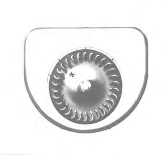
Flywheel
Remove the flywheel screen. Remove the flywheel nut and washer. The flywheel is mounted to a taper on the crankshaft. Take a firm hold of the fins and pull outward. At the same time, strike the end of the crankshaft with a soft hammer (Fig. 82). The flywheel will slide off the taper of the crankshaft and bearings. When reassembling the flywheel, be sure the Woodruff key is in position on the shaft and the keyway in the flywheel is lined up accurately with the key.
Air Shrouding
To disassemble air shrouding, first remove the cylinder head covers (Fig. 83) and the screws mounting the flywheel shroud to the lower cylinder shrouds and cylinder heat deflectors. Then remove the screws holding the flywheel shroud to the gear cover.
CARBURETOR & MANIFOLDS
The carburetor and manifolds can be removed in sections (Fig. 84).
In reassembly tighten the nuts for mounting the manifolds to 14 to 18 ft.–lbs. torque on model VF4 engines and 18 to 23 ft.–lbs. torque on model VH4 engines.
Cylinder Head
The cylinder head must be removed if it is necessary to regrind valves, or to do work on the piston rings or connecting rods. All of the cylinder head screws are plainly in view and can be easily removed. Screws of different lengths are used but these can be properly reassembled according to the various lengths of cylinder head bosses.
Before reassembling the cylinder heads, remove all carbon and lead deposits. Use new cylinder head gaskets in reassembly, as the old gasket will be so compressed and hard, they may not seal properly.
Use a mixture of graphite and oil on the cylinder head screws to prevent them from rusting tight against the cylinder block. Tighten cylinder head screws to 22 to 24 ft.–lbs. torque. After the initial run–in, retorque the head screws.
Gear Cover
Disconnect the governor linkage before removing the gear cover, since the same mounting screws are used for the governor housing and gear cover. Remove the gear cover screws and drive out the two dowel pins (Fig. 85). You can then remove the cover, exposing the timing gears (Fig. 86). In reassembly, tighten the cap screws to 14–18 ft.–lbs. torque.
Camshaft Gear
Remove the three cap screws and lock washers which hold the gear to the end of the camshaft (Fig. 86). Note that the camshaft gear has offset holes to provide accurate assembly for valve timing.
Idler Gear And Shaft
Remove the socket head (Allen–head) set screw that locks the idler shaft in place (Fig. 87). The screw is located in the side of the crankcase behind the distributor mounting flange. Remove the idler gear and shaft using a gear puller.
When reassembling, be sure the oil groove in the shaft is facing up. Drive the shaft into the crankcase with a soft metal hammer. Maintain a 0.0015 to 0.0035 inch clearance between the idler gear and the shoulder of the shaft.
Oil Pan
The engine can now be inverted so the supports and oil pan can be removed (Fig. 88). In reassembly, tighten the oil pan mounting screws to 6–9 ft.–lbs. torque.
Oil Pump
Remove the lock nut and pump driver gear from the shaft. If the gear is too tight to remove by hand, use a puller. Hammering on the end of the shaft to loosen the gear will damage the pump.
Remove the slotted pipe plug from the bottom of the crankcase (Fig. 89). Using a 5/32 inch Allen wrench, remove the lock screw from the pipe plug hole. Withdraw the oil pump from inside the crankcase. If the pump fits too tight to remove by hand, tap the front of the pump housing (not the shaft) with a hammer and brass rod.
In reassembly, be sure the lockscrew seat in the pump housing lines up with the lockscrew hole in the crankcase.
Pistons And Connecting Rods
Using a 1/2 inch socket wrench, loosen and remove the hex locknuts from the connecting rod bolts. By tapping the ends of thebolts, lightly, the connecting rod cap will release from the bolts.
Scrape off all carbon deposits that might interfere with removal of the position from the upper end of the cylinder. Turn the crankshaft until the piston is at the top of its stroke. Push the connecting rod and piston assembly upward and out through the top of the cylinder. Be careful not to scrape the crank pin by allowing the rod bolts to strike or scrape across it. Place the cap on the connecting rod immediately to prevent mismatching in reassembly. Be sure any shims are in place before putting the cap on.
NOTE: These models of engines were originally furnished with babbitt cast connecting rod bearings. Shell bearing rods are being used for current production engines. The shell bearing rods are interchangeable with babbitt bearing rods for service replacement.
A–01824
Fig. 86 Removing Camshaft Gear
Gear
Fig. 88 Removing the Oil Pan
Pipe Plug Lockscrew
Oil Pump
A–01831
Fig. 89 Removing Oil Pump Lockscrew
Be careful, in reassembly, to mount the bearings properly. The cap should be assembled to the rod so the locating lugs of the bearing halves are both toward the same side (Fig. 90). Refer to the chart (Fig. 95) for clearance between the bearing and crank pin.
When reassembling the piston to the engine, the wide section of the piston skirt must be toward the maximum thrust side (opposite the crankshaft rotation,(Fig. 91)). The clearance between the piston skirt and cylinder must be measured in the center of the thrust face at the bottom of the piston skirt. Refer to Specification Chart for proper skirt clearance.
In reassembly, be sure the piston and connecting rod assemblies are put back into the same bore from which they are removed. Use a suitable ring compressor and stagger the piston rings gaps 90 ° apart around the piston. Oil the pistons, rings, wrist pins, rod bearings and cylinder walls before assembly.
Important
Identical numbers are stamped on the side of the rod and its corresponding cap. These numbers must be on the same side of the connecting rod when installed in the engine. Be sure the hole in the connecting rod cap is facing toward the oil spray nozzle (Fig. 92). Install new nuts on the connecting rod bolts.
I–2146–1297
Piston Rings
If a ring expander tool is not available, install rings by placing the open end of the ring on the piston first (Fig. 93). Spread the ring only far enough to slip over the piston and into the correct groove, being careful not to distort the ring. Install the bottom ring first. Work toward the head of the piston, installing the top ring last.
Each piston has two compression rings, a scraper ring and an oil ring (Fig. 94). The outer diameter of the top compression ring is chrome plated. Mount the scraper ring with the scraper edge down, otherwise oil pumping and excessive oil consumption will result.
Cylinder Blocks
Clean all dirt and foreign deposits from between the cylinder fins and manifold ports.
92
Specification Chart
Mminches
VALVES & SEAT INSERTS
Remove the valve tappet inspection plate and compress the valve springs with a standard automotive type valve lifter (Fig. 96). Insert a rag into the opening at the bottom of the valve chamber so the retaining locks do not fall into the the engine crankcase. Remove the retaining lock, seats, springs and valves and clean these, as well as the ports and guides, of all carbon and gum deposits. Tag each valve so that in reassembly they will be mounted in the same guide they were removed from. Replace valves that are burned or pitted.
The exhaust valve face and replaceable exhaust seat inserts are of stellite material. A positive type valve rotator is furnished as standard equipment on the exhaust valves. Clean and inspect operation of the rotor.
The inlet and exhaust valve inserts can be removed, when replacement becomes necessary by using an insert puller.
Before grinding valves, inspect the valveguides for possible replacement. The valve face is ground at a 45° angle to the vertical centerline of the valve stem. The valve seat insert should also be ground at a 45 ° angle. After grinding, lap valves in place until a uniform ring will show entirely around the face of the valve. Clean the valves. Wash the block thoroughly with a hot solution of soap and water. Wipe the cylinder walls with clean, lint free rags and light engine oil, especially if the cylinders were rebored and honed.
Valve guides in the cylinder block are replaceable. The valve stem has a clearance of .003 to .005 inch in the guide. When the clearance becomes .007 inch, the guide should be driven out and a new pressed into place.
Crankshaft
To remove the crankshaft (Fig. 97), take out the six capscrews in the mainbearing plate at the take–off end. Pry the plate off and remove the crankshaft from the end of the crankcase. In reassembly, use the same quantity and thickness bearing plate gaskets and shims as were removed. They are necessary to provide end play for the tapered roller crankshaft bearings.
NOTE: End play should be 0.002 to 0.004 inch when the engine is cold.
There is practically no wear in these bearings, so readjustment is seldom necessary after proper assembly.
In reassembly, the timing marks on the crankshaft gear and camshaft gear must be aligned (Fig. 86), or the engine will not operate properly. If timing is off considerably, the engine will not run at all.
W–2288–0198
Valve Tappets
The mounting holes in the main bearing plate are offset so the plate will be correctly mounted for main bearing lubrication. Tighten the main bearing cap screws to 25 – 30 ft.–lbs. torque.
Camshaft
The camshaft must be removed from the flywheel end of the engine (Fig. 98). When replacing, be sure the spring and plunger are in place in the end of the camshaft, as they hold the camshaft in position endwise.
Valve Tappets
Take the valve tappets out after the camshaft is removed. In reassembly, the tappets must be inserted in their proper position in the crankcase before the camshaft is installed.
After the cylinder blocks have been assembled to the crankcase, adjust the valve tappets (Fig. 99). With the tappets in their lowest positions (engine cold) the clearance should be 0.008 inch for the inlet and 0.016 inch for the exhaust, with or without stellite valves.
TECHNICAL DATA (Wisconsin)
TROUBLESHOOTING GASOLINE & LPENGINES
Problem Cause Correction
Engine will not turn over with starter.
Blown fuse in the wiring harness. Loose battery connections.
Battery is discharged. Defective starter switch. Loose starter connections. Broken or disconnected wiring harness.
Replace the fuse.
Clean the battery terminals and re–attach the cables, tightening them securely.
Re–charge the battery. Check the function of the charging system. Replace the switch.
Tighten the connections securely. Reconnect or replace the wiring harness.
Engine fails to start or is difficult to start.
The variable speed is in high speed position.
The clutches are partially engaged with the steering lever in neutral position. The loader will tend to rock or move while starting. Improper starting procedure.
No fuel in the tank. The engine air cleaner is dirty.
The air vent hole in the fuel tank cap is plugged.
Leaky fuel line.
Damaged fuel pump
The carburetor is not being choked sufficiently, especially if the engine is cold.
The carburetor is being choked too much when starting a warm engine. The cylinders are flooded.
Water, dirt or gum in the gasoline is interfering with fuel flow. Dirty carburetor.
The ignition cable is disconnected from the magneto, distributor or spark plugs.
Broken ignition cables, causing short circuits.
The ignition cables, distributor or spark plugs are wet.
Moisture in the ignition system due to fertilizer dust settling into or around switches, fuses, ignition wire, battery terminals or distributor cap. The fertilizer dust draws moisture.
Pull the variable speed drive control lever all the way back before stopping the engine.
Adjust the clutches so the levers will travel 3 to 4 inches from neutral position, in each direction.
Refer to ”Starting Procedure” in the Bobcat Operation section of this Manual.
Refuel.
Service the air cleaner. Remove and clean the cap.
Correct as required.
Readjust, repair or replace.
Choke as required. If the cylinders start to flood, push the throttle control all the way forward. Start the engine. You should not normally need to choke an engine that is warm.
Crank the engine a few times with the spark plugs removed. Be carefulwhen doing this. Clean & dry the spark plugs.
Drain & clean the fuel system. Refill with clean fuel.
Correct as required.
Reconnect the ignition cable.
Replace broken ignition cables.
Dry and clean them.
Store the idle machine in a dry place as far as possible from stored fertilizer.
Blow fertilizer dust off the machine daily and wash it off frequently with diesel fuel.
Spray the ignition system with a sealant made to prevent moisture problems.