44 minute read
TROUBLESHOOTING GASOLINE & LPENGINES


Problem Cause Correction
Engine fails to start or is difficult to start (Cont’d)
The spark plugs are wet or dirty. The spark plug gaps are wrong. The ignition is out of time.
Faulty condenser or coil.
Faulty magneto or distributor.
The crankcase oil is too heavy (cold weather).
The valves are leaking or sticking.
Incorrect valve tappet adjustment.
Cylinders dry due to engine having been out of use for some time (poor compression).
Loose spark plugs.
Damaged cylinder head gasket or loose cylinder head.
Piston rings stuck in piston.
Scored cylinders (lack of compression).
Clean or replace the spark plugs.
Re–gap or replace the plugs.
Retime.
Replace.
Repair or replace.
Use an engine oil of the proper viscosity.
Clean and reseat the valves.
Adjust.
Restore compression by pouring a small amount of engine oil into the cylinders.
Install new gaskets & retorque plugs. Install new gaskets & retorque head.
Remove & clean the parts.
Correct as required.
Engine Misses.
Spark plug gap incorrect.
Wrong type spark plugs.
Improper ignition timing.
Fouled spark plugs.
Pitted breaker points.
Loose ignition cables or worn or broken cables.
Water in gasoline.
Poor compression.
Incorrect fuel mixture.
Dirty carburetor.
Clogged fuel screen.
Reset the spark plug gaps.
Check against recommendations.
Retime the engine.
Clean or replace. Check cause of fouling.
Check for cause.
Correct as required.
Drain & refill.
Tighten cylinder heads and spark plugs.
Readjust carburetor.
Clean.
Clean.
Engine Surges or Gallops.
Backfiring.
Carburetor flooding.
Governor incorrectly adjusted.
Lean fuel mixture.
Improper ignition timing.
Improper breaker point gap.
Sticky intake valve.
Check carburetor adjustment.
Readjust.
Readjust carburetor. Retime.
Readjust. Correct as required.
Engine Overheats.
Engine is overloaded.
Engine cooling fins are dirty.
Engine has been operated with part of the shrouding removed.
Dirty engine oil.
Operate at a lower variable speed setting.
Operate at a 3/4 to full throttle setting. Clean the cooling fins thoroughly.
Clean the cooling fins and replace the shrouding.
Change engine oil.
ONAN ENGINE SERVICE (444)
Engine Oil
Refer to the chart below for correct type of oil to use in the engine. Use a viscosity recommended when temperature at time of starting is as indicated in the chart. Use oil Service Classification SC, SD or SE.
Replace oil & filter after every 50 hours of loader operation. To replace oil remove the crankcase drain plug at the rear end of the engine, below the oil fill tube.
After draining, replace the plug and refill with 3 quarts of oilrecommended in the chart.
Temperature
Oil Viscosity
Below 0°F SAE 5W
0°F to 30 °F SAE 10W
30°F to 90 °F SAE 30
Above 90°F SAE 50
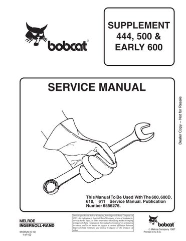
CRANKCASE BREATHER (Fig. 100)
Lift off the rubber breather cap. Carefully pry the valve fromthe cap; or press hard, with both thumbs on top of the cap and your fingers below, to release the valve from the rubber cap. Wash the fabric flapper type check valve in solvent. Dry and install it, with the perforated disc toward the engine.
GOVERNOR & SPEED CONTROL
The governor engine speed is 3000 RPM maximum, no load. Before making a governor adjustment, run the engine about 15 minutes to reach the normal operating temperature.
The speed at which the engine operates is determined by the tension applied to the governor spring. Increasing spring tension increases engine speed. Decreasing spring tension decreases engine speed.
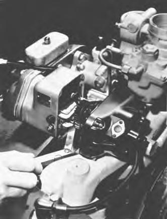
Carburetor Adjustment
To adjust the idle jet needle (Fig. 101), turn the idle adjusting needle IN untilthe engine loses speed. Then turn it OUT until the engine runs smoothly. A hunting condition at no–load can sometimes be corrected by an idle adjustment.
NOTE: Make the adjustment when the engine is running at normal operating temperature and no–load.
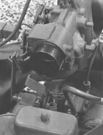
CARBURETOR RECONDITIONING (Gasoline)
Carburetor maintenance should consist of regular cleaning. Some gasolines have a tendency toward formation of gum deposits inside the carburetor which can usually be removed by soaking in alcohol or acetone. A fine, soft wire may be used to clean the jets.
Figure 102 shows the carburetor breakdown. When reconditioning the carburetor always use a repair kit. Refer to the Bobcat Parts Book.
Be sure the float is not damaged. If necessary to reset the float level, use a small screwdriver to bend the lip of the float. With the carburetor casting inverted and the float resting lightly against the needle in its seat, there should be 0.3125 inch (1/4 inch with styrofoam plastic float) clearance between the bowl cover gasket and the free end of the float (side opposite the needle seat) (Fig. 191).
Fuel Pump
A diaphragm type fuel pump is used (Fig. 103). If fuel does not reach the carburetor, check the fuel pump before dismantling it. The pump can be checked by disconnecting the fuel line at the carburetor, cranking the engine slowly, and observing whether fuel comes from the line at the carburetor. If there is enough fuel in the tank, and the line between the tank and pump is clear but the pump fails, repair or replace it. Failure of the pump is usually due to a leaking diaphragm, valve or valve gasket, a weak or broken spring, or wear in the drive linkage.
If you choose to repair the pump rather than replace it, use a repair kit.
NOTE: Always return the handpriming lever all the way inward so the priming lever does not prevent normal pump operation.
Gasoline diluted with oil may indicate a faulty fuel pump.
CARBURETOR RECONDITIONING (LP Gas)
To disassemble the carburetor:
1.With the carburetor inverted, loosen the check nut (Fig. 104), (Item 3) and remove the main adjustment screw (Item 2) and check nut from the fuel metering block. Remove the fuel block screws, fuel block (Item 4) and gasket (Item 19).
2.Remove the adapter plate screws and lockwashers (Item 5, 6, 20 & 21). Remove the adapter plate (Item 7) and gasket from the throttle body.
3.Remove the idle needle valve (Item 15) with its spring from the throttle body.
4.Remove the throttle screws (Item 17) and throttle plate (Item 18). Remove the throttle shaft and lever assembly (Item12). Remove the seal retainers (Item 11) with their seals (Item 10).
Never use a wire or drill to clean out the jets. Inspect all parts and replace any that are damaged or worn.
W–2289–0198
Thoroughly clean all metal parts, using a special carburetor cleaner. Rinse in solvent. Blow out all channels in the casting with compressed air. Reverse the air flow through each passage to insure removal of all dirt particles.
Inspect all parts and replace any that are damaged or worn. Always use arepair kit. For the correct repair kit to use, see your Bobcat Parts Book.
To reassemble the carburetor:
1.Place the adapter plate gasket (Item 8) on the throttle body and attach the adapter plate (Item 7) to the throttle body using two short screws and lockwashers (Item 6). Place a lockwasher onto the medium length screw (Item 21) before installing it. The long screw (Item 5) goes into the raised portion of the adapter. Tighten the screws uniformly.
2.Place the metering block gasket onto the adapter and attach the fuel metering block (Item 4). Assemble the check nut (Item 3) onto the main adjustment screw (Item 2). Thread the screw into the fuel block until the screw just contacts the seat. Back out the screw two full turns and tighten the check nut.
3.Place the spring on the idle needle valve (Item 15) and assemble the idle needle valve into the throttle body. Turn the needle valve IN lightly against its seat, then back OUT one turn.
4.Place the seals (Item 10) into their retainers and insert them into the throttle shaft counterbores from opposite sides. Insert the throttle shaft (Item12) and loosely attach the throttle plate (Item 18) to the throttle shaft with its screws. Make sure the throttle plate and shaft are assembled in the same way as before disassembly. Close the throttle. Align for best closing, then tighten the screws.
VAPORIZER – PRIMARY REGULATOR SERVICE
To service the vaporizer – primary regulator, see page 33.
VALVE SYSTEM (Fig. 106)
Properly seated valves are essential to good engine performance. The aluminum cylinder heads are removable for valve servicing. Do not use a pry to loosen the cylinder head, rap sharplyon the edge with a soft–faced hammer, taking care not to break any cooling fins. A conventional–type valve spring lifter may be used when removing the valve spring locks, which are of the slip type. Clean all carbon deposits from the cylinder heads, piston tops, valves, guides, etc. If a valve face is burned or warped, or the stem worn, install a new valve.
Worn valve stem guides may be replace from the inside the valve chamber. Valve locks are split, tapered–type, the smaller diameter of which must face toward the valve head. Tappets are also replaceable from the valve chamber after first removing the valve assemblies.
The valve face angle is 44 °. The valve seat angle is 45 °. This 1 ° interference angle results in a sharp seating surface between the valve and the top of the valve seat. The interference angle method of grinding valves minimizes face deposits and lengthens valve life.
The valves should not be hand lapped, if at all avoidable, since the sharp contact may be destroyed. This is especially important where stellite–faced valves and seats are used. Valve faces should be finished in a machine to 44°. Valve seats should be ground with a 45° stone, and the width of the seat band should be 0.0312 to 0.0468 inches wide. Grind only enough to assure proper seating.
Remove all grinding compound from engine parts and place each valve in its proper location. Check each valve for a tight seat, using an air pressure testing tool. If such a tool is not available, make pencil marks at intervals across the valve face and observe if the marks rub off uniformly when the valve is rotated part of a turn against the seat.
Lightly oil the valve stems and assemble all parts removed.
The positive–type valve rotocaps prolong valve life and decrease valve repairs. When functioning properly, the valve is rotated a fraction of a turn each time it opens. While at open position, the valve must rotate freely, but in only one direction. If rotocaps are faulty, install new rotocaps.
Tappet Adjustment
The engine is equipped with adjustable tappets. To make a valve adjustment, remove the covers. Crank the engine over slowly by hand until the left–hand intake valve (when facing the flywheel) opens and closes. Continueabout 1/4 turn until the mark on the flywheel and the TC mark on the gear cover are in line. This should place the left–hand piston at the top of its compression stroke, the position it must be in to get proper valve adjustment for the left–hand cylinder. Clearances are shown in (Figure 105) and the Table of Clearances. For each valve, the thinner gage (minimum) should pass freely between the valve stem and valve tappet, but the thicker gage (maximum) should not (Fig. 108).
To correct the valve clearance, simply turn the adjusting screw as needed to obtain the right clearance. The screw is self–locking, and will stay where set.
To adjust the valves on the right–hand cylinder, crank the engine over one complete revolution and again line up the mark on the flywheel and the TC mark on the gear cover. Then follow the adjustment given for the valves of the left–hand cylinder.
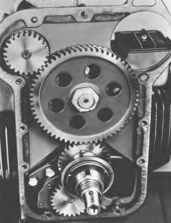
Ignition Timing
Spark advance is 25°. Remove the sheet metal plug from the top of the engine air housing. Note the timing marks stamped on the gear cover (Fig. 105).
1.Remove the cover from the breaker box. If the timing is very far off, attain an approximate setting by loosening the mounting screws and shifting the breaker box to align the witness marks on the cylinder blockand breaker box (Fig. 107).
2.Crank the engine over slowly by hand in the direction of crankshaft rotation until the witness mark on the flywheel and the TC mark on the gear cover are exactly in line.
3.Adjust the ignition breaker point gap width to 0.020 inch at full separation (Fig. 106).
4.Turn the flywheel to the left, against crankshaft rotation, until the timingmark is about two inches past the 25 ° mark on the gear cover.
5.Turn the flywheel slowly to the right and note whether the ignition points just separate when the mark on the flywheel aligns with the 25 ° mark on the gear cover.
If the mark aligns as the points break, timing is correct.
If they do not, loosen the breaker box mounting screws and shift the whole breaker box assembly slightly toward the No. 1 cylinder to retard the timing (points breaking too soon); shift it slightly away from the No. 1 cylinder to advance the timing (points not breaking soon enough).
Tighten the breaker box mounting screws securely after making the adjustment.
Spark Plugs
The spark plug gaps should be 0.025 inch for gasoline and 0.018 inch for LP gas.
Torque the spark plugs to 25–30 ft.–lbs. when installing.
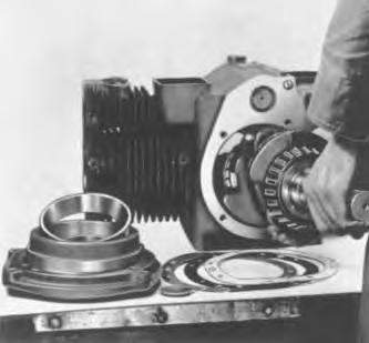
Engine Reconditioning
To disassemble the engine:
1.Gear Cover:
After removing the mounting screws, tap the gear cover gently with a soft faced hammer to loosen it.
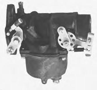
2.Governor Cup:
With the gear cover removed, the governor cup can be taken off after removing the snap ring from the camshaft centerpin. Catch the flyballs while sliding the cup off.
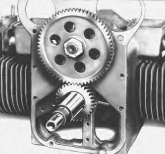
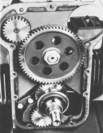
3.Timing Gears:
If replacement of either the crankshaft gear or the camshaft gear becomes necessary always install both gears new.
To remove the crankshaft gear, first remove the snap ring, then attach a gear pulling ring using two No. 10–32 screws. TIghten the screws alternately until both are tight. Attach a gear puller to the puller ring and proceed to remove the gear (Fig. 109).
The camshaft gear is pressed on and keyed to thecamshaft. The camshaft and gear must be removed as an assembly, after first removing the crankshaft gear lock ring and washer. Before removing the camshaft and gear assembly, remove the cylinder head and valve assemblies. Then remove the operating plunger for breaker points, the fuel pump and the tappets. After removing the governor cup assembly from the gear, the camshaft may be pressed out of the gear byusing a hollow tool or pipe which will fit over the camshaft center pin. Do not press on the center pin or damage it in any way. The governor ball spacer is a press fit to the camshaft gear.
4.Pistons and Rings:
The piston and connecting rod assemblies are removed from the top of the cylinder. The pistons are fitted with two compression rings and one oil control ring with an expander.
Inspect each piston. The piston ring grooves should be cleaned of any carbon deposits and the oil return slots in the lower groove must be open.
5.Bearings:
Removal of the camshaft or camshaft bearings requires complete disassembly of the engine. Use a press or a suitable drive plug to remove the bearings. Support the casting to avoid distortion and avoid damaging the bearing bore during removal and installation. Use oil on the bearings to reduce friction when installing and again lubricate with oil after installing.
6.Oil Seal:
The bearing plate must be removed to replace the oil seal. Drive the oil seal out from the inside.
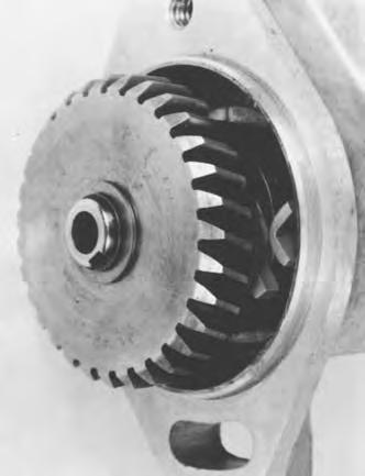
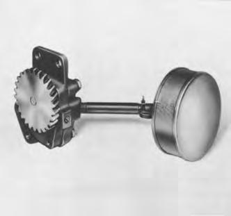
7.Oil Pump:
To remove the oil pump, it is necessary to detach the intake cup assembly (Fig. 110).
8.Cylinder:
The cylinder wears very little in normal service. If, through improper lubrication or accident, the cylinder wall should become scored or badly worn, the cylinder may be rebored and honed to accommodate a new piston and rings of one of the available oversizes. Pistons are available in 0.010, 0.020, 0.030, and 0.040 inch oversize. Piston rings are available in 0.010, 0.020, 0.030 and 0.040 inch oversize.
Use standard rings in a 0.005 inch oversize piston. If the cylinder is notbeing reconditioned, but new piston rings are being installed, remove any ridge which may have formed at the top of the piston ring travel in the cylinder bore. An engine might be fitted with a 0.005 inch oversize piston and is so indicated by a letter E following the engine serial number. The serial number is stamped on the cylinder block and on the engine nameplate. The standard cylinder bore size appears in the Table of Clearances (See Page 58).
To reassemble the engine:
1.Oil Pump:
Check the oil pump thoroughly for worn parts. Oil the pump to prime it before reinstalling. Except for gaskets and the suction cup, the component parts of the pump are not available individually. Install a new pump assembly if required (Fig. 110).
Engine oil pressure is easily adjusted by means of the slotted stud and locknut located near the breather tube (Fig. 111). Oil pressure readings when the engine is warmed up should be between 20 and 35 PSI. To increase oil pressure, loosen the locknut and turn the stud inward. To decrease oil pressure, loosen the locknut and turn the stud outward. Be sure to tighten the locknut securely after making an adjustment. The spring and plunger can easily be removed and cleaned.
2.Bearings:
New crankshaft main bearings are precision type which do not require line reaming or line boring after installation. They are available in standard size 0.002, 0.010, 0.020 or 0.030 inch undersize. Expand the bearing bore by placing the casting in hot water or in an oven heated to 200 °F.
If a torch is used, apply only a little heat.
If practical, cool the precision bearing to shrink it. Align the oil hole(s) in the bearing with the oil hole(s) in the bearing bore. The oil passage must be at least 1/2 open. The cold oiled precision bearing should require only light taps to position it (Fig. 112). Install the bronze faced bearing flush with the inside of the bore.
If the head of a lock pin is damaged, remove it and install a new pin. Apply oil to the thrust washer to hold it in place while installing the crankshaft. Oil grooves in the thrust washers must face the crankshaft. The washers must be flat (not bent) and the two notches must fit over the two lock pins to prevent riding on the crankshaft. New camshaft bearings are precision type which do not require line reaming or line boring after installation. Coat the bearing with lubricating oil to reduce friction. Place the bearing on the crankcase over the bearing bore with the elongated hole in proper position and the narrow section facing out (except, in bores withoutoil holes, install with bearing groove at the top). Be sure to start the bearingstraight. Press the rear bearing in flush with the bottom of the counterbore which receives the expansion plug.
3.Oil Seals:
Before installing the seals, fill the space between the lips with a fibrous grease or stiff cup grease. This will improve sealing (Fig. 113).
When installing the gear cover oil seal, tap the seal inward until it is 0.968 inch from the mounting face of the cover.
NOTE: Install a new style, thin, open face seal 1.1093 inch from the mounting face of the cover.
When installing the bearing plate oil seal, tap the seal into the bearing plate bore to bottom against the shoulder in the plate bore. Use a seal expander or place a piece of shim stock around the end of the crankshaft when replacing the bearing plate to avoid damaging the seal. Remove the shim stock as soon as the plate is in place.
4.Crankshaft:
Inspect the bearing journals. If they are scored and cannot be smoothedout by dressing down, the bearing journals should be refinished to use the nearest available undersize bearings or a new crankshaft should be installed. If a worn main bearing journal cannot be fitted with an available precision type undersize bearing, then refinish it to the next undersize.
If a worn rod journal cannot be fitted by installing a new bearing insert, refinish it to take the corresponding undersize rod or bearing insert available. Inspect the drilled passages of the crankshaft. Clean them to remove any foreign material and to assure proper lubrication of the connecting rods.
After the crankshaft is installed, measure end play (Fig. 114).
5.If the pistons are badly scored, very loose in the cylinder, have badly worn ring grooves, or otherwise are not in good condition, install new pistons. Install new pistons if they are so loose on the piston pins that a 0.002 inch oversize pin will not correct it. Handle the pistons carefully to avoid nicking the walls. Any raised surface of this type must be dressed down carefully.
Inspect the rings carefully for fit in the grooves, for tension and for seating on the cylinder walls. If in doubt, install new rings.
Before installing new rings, check the ring gap by placingeach ring squarely in its cylinder at a position corresponding with the bottom of its travel (Fig. 115). The gap between the ends of the ring should be as given in theTable of Clearances, See Page 58.
Slightly oversize rings may be filed as necessary to obtain the correctgap, but do not use rings which require too much filing. Standard size rings may be used on 0.005 inch oversize pistons; 0.010, 0.020 0.030 and 0.040 inch oversize rings are to be used on the corresponding size piston. Tapered rings are usually marked TOP on one side, or identified in some other manner. These rings must be installed with this mark toward the piston head. Space each ring gap one third of the way around the piston from the preceding one, with no gap directly in line with the piston pin. The bottom piston ring groove should be fitted with an expander and an oil control ring and the two upper rings fitted with compression rings (Fig. 116).
The piston is fitted with a full floating piston pin. The pin is kept in place by two lock rings, one at each side. Be sure these lock rings are properly positioned in their groove before installing thepiston and connecting rod into the engine. Correct piston to cylinder clearance appears in the Table of Clearance.
6.Connecting Rods:
The connecting rods should be serviced at the same time the pistons or piston rings are serviced. Rod bearing inserts are available in 0.002, 0.010 or 0.030 inch undersize.
For clearances, refer to the Table of Clearances.
The connecting rod and piston assembly must be properly aligned before reassembly to the engine. The aligning should be done on an accurate aligning gauge by a competent operator. Misalignment may cause rapid wear of the piston, pin, cylinder and connecting rod.
Install the connecting rods and caps with the raised lines (witness marks) aligned, and with the caps facing toward the oil base. The rod and cap numbered two fits on the crankshaft journal nearer the bearing plate. Coat the crankshaft journal bearing surfaces with oil before installing the rods. Crank the engine by hand to see that the rods are free. If necessary, rap the connecting rod cap screws sharply with a soft faced hammer to set the rod square on the journal.
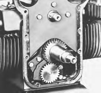
7.Timing Gears:
When pressing a gear onto the camshaft, be sure it started straight and the key is properly in place. Install the governor cup assembly before installing the camshaft and gear.
Each timing gear is stamped with an O near the edge (Fig. 117). The gear teeth must meet so these marks exactly coincide when the gears are installed in the engine. When installing the camshaft gear and shaft assembly, be sure the thrust washer is properly in place behind the camshaft gear. Then install the crankshaft retaining washer and lock ring.
8.Governor Cup:
Replace with a new part, any flyball which is grooved or has a flat spot; the ball spacer, if its arms are worn or otherwise damaged; andthe governor cup, if the race surface is grooved or rough. The governor cup must be a free spinning fit on the camshaft center pin, but without any excessive play.
When installing the governor cup, tilt the engine so the gear is up, put the flyballs into place (equally spaced) and install the cup and snap ring on the center pin.
The camshaft center pin extends out 0.750 inch from the end of the camshaft. This distance provides an in and out travel distance of 0.2187 inch for the governor cup (Fig. 118). Hold the cup against the flyballs when measuring.
If the distance is less (the engine will race, especially at no load), remove the center pin and press in a new pin or grind off the hub of the cup as required. The camshaft center pin cannot be pulled outward or removed without damage. If the center pin extends out too far, the cup will not hold the flyballs properly.
9.Gear Cover:
When installing the gear cover, make sure the pin in the gear cover engages the metal lined (smooth) hole in the governor cup. Turn the governor cup so the metal lined hole is at the three o’clock position. The smooth side of the governor yoke must ride against the governor cup. Turn the governor arm and shaft clockwise as far as possible and hold in their position until the gear cover is installed flush against the crankcase. Be careful no to damage the gear cover oil seal. Adjust the roll (stop) pin to protrude to a point 0.750 inch from the cover mounting surface (Fig. 119).
0.2187”
Center Pin Snap Ring
Governor Cup
When Governor Is Properly Assembled, The Dimension Shown On Drawing Will Be As Indicated. Camshaft Gear Camshaft
Fig. 118 Installing Governor
Governor Shaft
If Feeler Will Enter Hole 0.500”, Ball Has Fallen Out
PI–01448D
Governor Cup Rotate Governor Cup So That Roll Pin Fits Into The Metal Lined Hole In The Cup
Governor Arm Governor Shaft
Governor Shaft Yoke
Roll Pin (Smooth Side Toward Cup)
Oil Seal
PI–01447A
Fig. 119 Installing Gear Cover
TECHNICAL DATA (Onan)
FITS & CLEARANCES
(All Clearances Given at Room Temperature of 70°F.)
Torque Values
KOHLER ENGINE SERVICE (500)
Engine Oil
Refer to the chart below for correct type of oil to use in the engine. Use a viscosity recommended when temperature at time of starting is as indicated in the chart. Use oil Service Classification SC, SD or SE.
Replace oil & filter after every 50 hours of loader operation. To replace oil remove the crankcase drain plug at the left side of the engine, below the variable drive sheave.
After draining, replace the plug and refill with 4 quarts of oilrecommended in the chart.
Temperature
Oil Viscosity
Below 0°F SAE 5W–20
0°F to 30 °F SAE 10W–30
Above 30°F SAE 30
Compression Check
A commercial compression testing gauge should be used in the manner indicated by the manufacturer. An engine in top mechanical condition will show compression of 110 to 120 PSI.
When this figure falls below 100 PSI it indicates leaking rings or valves, or deposits in the combustion chamber which limit the charge entering the combustion chamber.
NOTE: The above reading is based on running the engine at 1000 RPM.
Compression over 130 PSI indicates a need for removing carbon deposits from the combustion chambers.
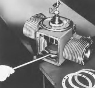
Crankcase Breather
The crankcase breather valve is used to maintain a slight vacuum in the crankcase. All parts must be clean and in good condition. A faulty breather valve may cause high engine temperatures and oil leaks at all engine seals.
An engine in good condition will have crankcase vacuum of 10 to 20 inches water column as read on a V–tube water manometer. If a vacuum is not within the specified range, this could be caused by one of the following:
1.Clogged crankcase Breather–Can cause positive pressures to buildup in the crankcase. Disassemble and clean the breather assembly. Re–check the pressure after reinstalling the breather valve.
2.Worn Oil Seals–Can cause lack of vacuum. Oil leakage is usually evident around worn oil seals.
3.Blowby–Leaky Valve–Can cause positive pressures. Make a compression test on the engine.
GOVERNOR & SPEED CONTROL
Operating speed is determined by the throttle control setting. The governor maintains engine speed over varying loads and serves as a top speed limiting device. A stop (Fig. 120, Item A) is provided to prevent exceeding the recommended top speed.
Governor sensitivity may be adjusted by means of a screw (Fig. 120, Item B). If too sensitive, speed surging on change of load (hunting) may occur. A sudden drop in speed when a load is applied indicates that the governor should be set for greater sensitivity. To increase sensitivity, increase spring tension by turning the hex nuts farther onto the eye screw(Fig. 120, Item B). Relieve spring tension to decrease sensitivity.
NOTE: When sensitivity is changed, the speed stop screw (Fig. 120, Item A) setting must also be changed.
When sensitivity is increased, the stop screw should be turned out to maintain 3200 RPM maximum. Turn the screw in when sensitivity is decreased.
Carburetor Adjustment
1.This carburetor is a fixed jet type and no adjustment can be made of the high speed mixture (jets are available for high altitude operation).
2.The idle speed screw (Fig. 121, Item A) adjustment should be made to an engine speed no less than 1000 RPM.
3.If the idle speed screw is completely out of adjustment and the engine will not start, turn it in lightly against the seat. Back it out 1–1/4turns. Follow step 2 for final adjustment after starting the engine.
4.Be sure the choke cable is adjusted to full choke position.
CARBURETOR RECONDITIONING (Gasoline Fig. 122)
To remove the fuel bowl:
1.With the carburetor inverted, loosen the fuel bowl plug (Item 41).
2.Remove the four fuel bowl assembly screws (Item 40). Separate the fuel bowl (Item 39) from the throttle body assembly.
3.Remove the bowl to body flange gasket (Item 36).
To disassemble the throttle body:
1.With the throttle body inverted, remove the float axle (Item 32) by pressing against the end of the axle with the blade of a small screwdriver. Remove the float assembly.
2.Remove the discharge tube and well assembly (Item 35). Remove the rubber seal (Item 34) from the end of the tube.
3.Remove the fuel valve (needle and seat) (Item 31) with its gasket (Item 28).
4.Remove the idle adjusting needle (Item 18) and spring (Item 19).
5.Mark the throttle lever and throttle body with a file or prick punch as a guide to correct assembly. Remove the throttle plate screws (Item 22), throttle plate (Item 21) and throttle lever and shaft assembly (Item 24).
NOTE: If screws are riveted, they must be filed away before the screws can be removed. Do not attempt to re–rivet upon assembly.
6.Remove the throttle shaft seal (Item 17) and retainer (Item 15) from each side of the throttle body, using a small screwdriver to lift the parts out of the shaft holes.
7.Mark the choke lever, choke bracket and adjacent shaft boss with a file or prick punch as a guide to correct reassembly. Remove the choke lever return spring (Item 14).
8.Remove the choke plate screws (Item 30) and choke plate (Item 29). Remove the choke shaft nut (Item 2), lockwasher (Item 3) and lever (Item 4).
9.Remove the choke bracket screws (Item 7), lockwashers and bracket (Item 13).
10.Remove the choke shaft (Item 6), choke shaft seal (Item 9) and retainer (Item 8) from the choke shaft boss. Use a small screwdriver to lift out the retainer and seal.
11.Insert a 6 inch length of 0.125 inch diameter rod into the shaft hole anddrive out the choke shaft plug (Item 27).
To disassemble the fuel bowl:
1.Remove the main jet (Item 37) and fiber washer (Item 38).
2.Remove the fuel bowl drain plug (Item 41).
Thoroughly clean all metal parts, using aspecial carburetor parts cleaner. Rinse in solvent. Blow out all passages and channels in the castings with compressed air. Reverse the air flow through each passage to insure the removal of all dirt particles.
Warning
Never use a wire or drill to clean out the jets. Inspect all parts and replace any that are damaged or worn.
W–2286–0198
Inspect all parts and replace any that are damaged orworn. Always use a repair kit. For the correct repair kit to use, see your Bobcat Parts Book.
To reassemble the fuel bowl assembly:
1.Install the main jet (Item 37) with its fiber washer. Install the fuel bowl drain plug (Item 41) but do not tighten at this time.
To assemble the throttle body assembly:
1.Install a new choke shaft seal (Item 9) (lip side out) and retainer (Item 8).
2.Attach the choke bracket (Item 13) with lockwashers andscrews. Make sure the bracket is aligned to the match marks made at the time of disassembly.
3.Insert the blank end of the choke shaft (Item6) into the choke shaft hole and rotate the shaft so the flat side is out. Attach the choke plate loosely with its screws. Close the choke. Align the choke plate for best closing. Tighten the screws.
4.Assemble the choke lever to the choke shaft with a lockwasher (Item 3) and nut (Item 2). Align the lever to the match marks during disassembly. Tighten the nut.
5.Install new throttle shaft seal (Item 17) into the retainer (Item 15) with the lip of the seal in the open side of the retainer.
6.Press the seal and retainer into the throttle shaft hole until the outer face of the retainer is flush with the shaft boss. Slight tapping with a light hammer may be required. Repeat at both sides of the throttle body.
7.Install the throttle shaft and lever assembly (Item 24) with a slight twisting motion of the shaft to ease the shaft through the seals.
8.Attach the throttle plate (Item 21) to the throttle shaft, leaving the screws loose. Close the throttle and align the plate for best closing. Tighten the screws.
9.With the throttle body inverted, install a new fuel valve seat (Item 31) with a new gasket. Use a wide blade screwdriver or seat wrench.
10.Insert the cone end of the fuel valve needle in the fuel valve seat. Place the float and lever assembly (Item 33) in position on the throttle body. Align the hole in the float lever bushing with the holes in the axle bracket. Install the float axle.
11.With the throttle body inverted and the float lever holding the needle valve on its seat, check the distance from the throttle body flange to the top of each float. This dimension should be 1.2031 inches (Fig. 123).
12.Install the idle adjusting needle (Item 18) and spring. Turn the needle IN lightly against its seat. Back the needle OUT 1–1/4 turns as a preliminary adjustment.
13.Apply a light coating of lubricating oil to the shoulder end of the discharge tube and well assembly (Item 35) to hold the seal (Item 34) in place. Install the seal end of the assembly into the discharge port of the throttle body.
To assemble the fuel bowl to the throttle body:
1.Place a new body to bowl gasket on the throttle body and position the fuel bowl on the throttle body.
2.Align the holes in the fuel bowl with the holes in the gasketand throttle body. Insert the four assembly screws. Tighten them evenly and securely.
3.Securely tighten the drain plug in the fuel bowl.
Electric Fuel Pump Service
To disassemble an electric fuel pump:
1.With a 0.625 inch wrench, release the bottom cover (Fig. 124, Item 1) from the bayonet fittings. Twist the cover by hand to remove it from the pump body.
2.Remove the filter (Item 4) magnet (Item 3) and cover gasket (Item 2). Wash the filter in cleaning solvent and blow out dirt and cleaning solvent with air pressure. Check the cover gasket and replace if deteriorated. Clean the cover.
3.Remove the retainer spring (Item 5) from the plunger (Item 11) using a thin nose plier to spread and remove the ends of the retainer from the tube. Then remove the washer (Item 6), O–ring seal (Item 7), cup valve (Item 8), plunger spring (Item 9) and plunger (Item 10) from the tube (Item 11).
4.Wash the parts in cleaning solvent and blow clear with air pressure. If the plunger does not wash clean or if there are any rough spots, gently clean the surface with crocus cloth. Slosh the pump assembly in cleaning solvent. Blow out the tube with air pressure. To do a complete job, swab the inside of the tube with a cloth wrapped around a stick.
To reassemble an electric fuel pump:
1.Insert the plunger assembly (Item 10) into the tube with the buffer end first. Check the fit by slowly raising and lowering the plunger in the tube. It should move fully without any tendency to stick. If a click cannot be heard, the interrupter assembly is not functioning properly. In this case the pump should be replaced.
2.To complete the assembly, install the plunger spring (Item 9), cup valve (Item 8), O–ring seal (Item 7) and washer (Item 6). Compress the spring (Item 9) and insert the retainer (Item 5) with the ends of the retainer in the side holes of the tube (Item 11).
3.Place the cover gasket and magnet in the bottom cover and assembly and filter and cover assembly. Twist the cover by hand to hold it in position on the pump housing. With a 0.625 inch wrench, securely tighten the bottom cover.
Important
To inspect and adjust:
Do not tamper with the seal at the center of the mounting bracket (at the side of the pump) as it retains the dry gas, which surrounds the electrical system, in the upper portion of the pump.
Electric fuel pump delivery should be 1.750 PSI maximum. Use a low pressure gauge or water manometer to check this. Pressure can be increased or decreased by stretching or compressing the spring.
CARBURETOR ADJUSTMENTS (LPG)
1.Turn the high speed needle counterclockwise one and one half turns (from closed position), and start the engine.
2.When the engine reaches normal operating temperature, accelerate and check response. Operate the engine under load and adjust the high speed needle for the leanest mixture which will allow satisfactory acceleration and steady governor operation.
3.If the engine misses and backfires, the high speed mixture is too lean. The high speed adjustment screw must be turned counterclockwise 1/4 turn at a time to correct this condition.
4.If the engine shows sooty exhaust and is sluggish, the mixture is too rich.To correct, the high speed adjustment screw should be turned clockwise until smooth running is reached.
5.To make a final check of the high speed adjustment, operate under full load and make other corrections necessary.
6.Idle speed screw adjustments should be made at a speed notless than 1000 RPM. Adjust the idle mixture screw (approximately 2–1/2 turns open) until smoothest idle is obtained.
Warning
Do not use force on the high speed needle or idle mixture screw–they will be damaged.
CARBURETOR RECONDITIONING (LP Gas) (Fig. 125)
To disassemble the LP carburetor:
1.Turn the throttle stop screw (Item 43) to the left until the throttle plate is fully closed.
2.Remove the throttle plate screws (Item 34) and throttle plate (Item 33).
3.Remove the throttle shaft (Item 44).
4.Remove the throttle shaft seal retainers and seals (Item 35 &36).
5.Take out the venturi retainer screw and remove the venturi (Item 32).
6.Remove the choke plate screw, choke plate (Item 31) and choke shaft (Item 49).
7.Remove the idle adjusting needle and spring (Item 38 & 39).
8.Remove the four idle diaphragm cover screws (Item 57) cover (Item 56) and idle diaphragm (Item 55). Remove the control channel plug (Item 37), fiber washer and spring (Item 41 &42).
9.Remove the lever axle (Item 51), diaphragm lever (Item 54) and rubber valve disc (Item 52).
10.Remove the two diaphragm housing screws (Item 53), housing (Item 50) and gasket (Item 40).
11.Remove the diaphragm cover assembly screws (Item 2) and diaphragm assembly (Item 3 thru 7).
12.Separate the diaphragm assembly components.
13.Remove the axle retainer, fuel valve axle (Item 12) and fuel lever (Item 10).
14.Remove the inlet orifice (Item 18). The orifice is secured in position with an 8–32 socket head (Allen Head) set screw. Loosen this set screw before attempting to remove the inlet orifice.
15.Remove the inlet valve stem (Item 21) and spring.
16.Remove the adjusting needle from the main jet adjustment (Item 16).
17.Use a 0.625 inch socket wrench to remove the main jet adjustment body (Item 16).
18.Use a special jet wrench to remove the main jet (Item 14).
Thoroughly clean all metal parts, using aspecial carburetor parts cleaner. Rinse in solvent. Blow out all passages and channels in the casting with compressed air. Reverse the air flow through each passage to insure the removal of all dirt particles.
Never us a wire or drill to clean out the jets. Inspect all parts and replace any that are damaged or worn.
W–2286–0198
Inspect all parts and replace any that are damaged orworn. Always use a repair kit. For the correct repair kit to use, see your Bobcat Parts Book.
To reassemble the carburetor:
1.Install the main jet (Item 14) and compensator jet (Item 13).
2.Place a new fiber washer on the main jet adjustment body. Install and tighten with a 0.625 inch socket wrench.
3.Place a new o–ring on the main jet adjusting needle. Seat the adjusting needle then back it out 2 or 3 turns.
4.Place a new rubber seat on the fuel valve stem (Item 21).
5.Place the fuel valve spring (Item 22) on the fuel valve (Item 21). Insert the valve, spring end first, into the casting.
6.Place a new O–ring on the inlet orifice (Item 18) and turn it part–way into the casting.
7.Insert the tip of the fuel valve lever into the slotin the valve stem (Fig. 126). Install the axle and axle retainer.
8.Place the special fuel valve lever adjusting gauge on the machined surface of the casting and against the nylon roller (Fig. 127). Adjust the fuel valve lever to step 2 on the gauge by turning the inlet orifice in or out. Secure it in position by tightening the 8–32 set screw (Fig. 128).
NOTE: The fuel valve lever is not adjustable on early type carburetors.
9.Install aligning studs in three of the diaphragm mounting screw holes.
10.Install the diaphragm assembly components in this order:
NOTE: Install the components so the vacuum port and vent channel port openings are in the right positions.
Gasket (Fig. 125, Item 7)
Inner Diaphragm (Item 6)
Diaphragm Spacer (Item 5)
Outer Diaphragm (Item 4)
Diaphragm Cover (Item 3)
11.Install three diaphragm assembly screws (Item 2). Remove the aligning studs and install the remaining screws.
12.Install the venturi and secure it with the venturi screw.
13.Place the idle diaphragm gasket on the housing and fasten the housing to the carburetor body with 3/4 inch long screws.
14.Insert a new valve disc in the lever assembly from the lever arm side. Position the lever in the housing and secure it with the lever axle.
15.Align the diaphragm and cover on the housing with the cup side of the diaphragm next to the lever. Install the attaching screws and lockwashers.
16.Insert the spring into the idle channel plug. Place the fiber gasket on the plug. Install the plug into the housing.
17.Install the throttle shaft seals and seal retainers. Secure the retainers by staking.
18.Install the throttle plate.
19.Install the idle adjusting screw and spring. Turn the screw in lightly against its seat, then adjust the needle to 1–1/2 to 2 turns open.
20.Place the choke return spring on the choke shaft. Install the choke shaft and choke plate with the relief spring outward.
21.Turn the throttle stop screw to its right to open the throttle for a fast idle.
Fuel Valve Lever
Fuel Valve Seat
Fuel Valve Axle
Fuel Valve & Spring
Axle Retainer
A–01814
Fig. 126 Installing Fuel Valve Lever
VAPORIZER–PRIMARY REGULATOR SERVICE
To service the Vaporizer – Primary Regulator, see page 33.
8–32 Allen Set Screw Wrench
A–01816
Fig. 128 Securing Fuel Valve Lever
Ignition Timing
The engine is equipped with a timing sight hole which is located on top of the blower housing. Timing marks on the rim of the flywheel (Fig. 130). When the engine is turned in a clockwise direction toe marks will be seen in the following order: 90°–M–SP–DC
To correctly time the magnets to the engine:
1.Remove the No. 1 spark plug. The No. 1 cylinder is on the left side when facing the timing sight hole.
2.Turn the engine over by hand until compression is on the No. 1 cylinder and the M mark is centered in the timing sight hole.
3.Turn the magneto gear counterclockwise until the small white markappears in the sight window of the magneto cover. The gear will now be in a tightened position. You will feel a resistance at this point. The impulse lever and stop will be in the position shown in figure 129.
4.Install the magneto with the gear in this position and hold it as straight as possible. Watch the gear when installing to be sure it does not move from its position.
5.Turn the top of the magneto toward the front of the machine all the way into the slotted holes. Turn the engine flywheel counterclockwise one half turn and then clockwise until the mark for 5 ° ahead of DC is in the sight hole. Now slowly turn the magneto to a vertical position until a loud click is heard.
6.Final setting can be made with a timing light. Move the magneto until theSP mark is centered in the sight hole.
NOTE: On engines equipped with an LP gas carburetor, the SP mark should be set to the left of center lining up with the edge ofthe sight window when facing the engine from the front or blower side. This will give an increase in spark advance, which is permissible when LP gas fuel is used.
Using Timing Light
Follow the manufacturer’s instructions for using a timing light. Basically, these steps should be used:
1.Connect one lead of the timing light to either spark plug or spark plug lead.
2.Connect one lead of the timing light to the ungrounded side of the battery.
3.Connect one lead from the timing light to a ground.
4.When the engine is running, aim the light into the timing sight hole so that the markings on the flywheel can be seen. S or SP should appear whenthe engine is running at maximum RPM.
Magneto Service
1.Check the magneto output by placing the end of a spark plug cable about 0.1250 inch from the engine and cranking at normal speed.
2.If there is no spark, check the breaker points.
3.If the contact points are dirty, they may be cleaned with lacquer thinner. Wipe them dry, but make sure no particles of lint or oily film are left between the point surfaces. If pitted or burned, the points should be replaced.
To reset the breaker points:
1.The breaker contact should be adjusted to .015 when fully opened. Turn the flywheel until the points are wide open at the high point on the breaker cam. To adjust the points, follow these steps.
2.Loosen the two clamps so the contact plate can be move.
3.Insert a small screwdriver in the adjusting slot.
4.Open or close the points by moving the plate until the opening is .015 inch (Fig. 131).
5.Tighten the two clamp screws.
6.If poor ignition persists, check the condition of the coil and condenser with a good commercial tester.
The only lubrication point in the magneto is the cam wiper felt. This felt should be replaced whenever it is necessary to replace the breaker points.
Electrical System
The alternator system used on the engine provides electrical power to change the 12 volt battery. This system has the following basic components:
1.Permanent Field Magnet Ring.
2.Alternator Stator.
3.Full Wave Rectifier.
4.Voltage Regulator.
As the permanent field magnet ring rotates around the stator, an alternating current is induced in the primary or load winding of the stator. The current produced is approximately 30 amperes. This AC current flows to the full wave rectifier where it is rectified to direct current which flows to the battery.
To adjust the voltage, remove the regulator cover and connect a voltmeter to the battery terminals. Be sure that the battery load is less than the alternator output so the unit is regulating. With the alternator running at about half speed, adjust to desired voltage by turning the voltage adjustment screw (Fig. 132). Turn clockwise to increase: counterclockwise to reduce.
ELECTRICAL CIRCUITRY (S/N 42806 & Below)
GENERATOR OUTPUT TEST:
Disconnect the black wire from the A terminal of the generator.
Connect a lead from the A terminal of the generator to an ammeter (+) terminal. Connect a lead from the ammeter (–) terminal to the battery (+) terminal.
Connect a jumper lead from the generator F terminal to the ground screw on the generator body.
Run the engine at full throttle and check the output. It should be at least 14 amps.
If the generator output is acceptable and the battery remains under charge, but you still have problems, replace the regulator.
NOTE: After rebuilding a generator, you will need to polarize the generator to insure that its polarity will match that of the battery.
To polarize the generator, disconnect the F wire from the regulator and momentarily touch the B terminal on the regulator. C–01376
Engine Reconditioning
To disassemble the engine:
1.Disconnect the spark plug wires.
2.Disconnect the fuel line, governor linkage and choke cable from the carburetor.
3.Remove the shrouding.
4.Remove the intake and exhaust manifolds from the engine.
5.The flywheel is mounted on a tapered shaft. Use a puller, to prevent damage to the crankshaft, when removing the flywheel.
6.Remove the magneto and governor units from the engine.
7.Disassemble the breather. Remove the gear cover and shroud mounting plate.
8.Remove the cylinder heads. Clean deposits from the cylinder bore, piston and combustion chamber.
9.Take off the valve chamber covers. Remove the retainer keys, rotators, retainers, springs and valves.
10.Push out the flywheel key. Slide the front oil seal off the shaft (Fig. 135).
11.Loosen the nut on the camshaft. Remove the nut and gear from the shaft. Remove the cover plate by taking out the three cap screws. Remove the camshaft.
12.Using two large screwdrivers, pry the drive gear and key from the crankshaft.
13.At this point the oil must be drained from the crankcase.
Place the flywheel onto the crankshaft. Tip the engine forward, using the flywheel as a supporting base.
14.Remove the starter and generator.
15.Remove the oil base cap screws. Remove the oil base, oil pump intake pipe and screen, and baffle plate.
16.Remove the connecting rod caps and bearings. Push the piston and rod assemblies out of the top of the cylinder bore after cleaning the deposits from the lip.
17.Take off the closure plate assembly and remove the crankshaft from the cylinder block.
18.The valve tappets can now be taken out from the inside of the cylinder block.
19.Tip the cylinder block off the flywheel base and remove the oil pump from the front of the block.
20.Check the condition of the camshaft bearings and oil transfer bearings. If worn beyond the clearances shown on page 125, replace them.
21.The roller bearing races in the end plate and cylinder block should not be removed unless badly scored or grooved. If replacement is necessary, drive the race out of the block with a drift punch.
22.The roller bearings must be pressed from the crankshaft if replacement is necessary. The roller bearings used in this engine are of extra large capacity, designed to give long service life.
After cleaning all parts, inspect them carefully to determine which are reusable.
1.Cylinder Block:
If badly scored, tapered or out of round more than 0.005 the cylinder should be rebored.
Always bore or rebore to exactly 0.010, 0.020 or 0.030 over the standard bore size of 3.625.
Use an inside micrometer or dial gauge to determine cylinder wear before and during honing.
If honed to the nearest available oversize mentioned above, oversize piston and ring assemblies can be used without any additional fitting, as proper clearances will have been allowed.
Any commercial cylinder hone can be used with either a drill press or a portable electric drill. The drill press is preferable as it is important to keep the bore in alignment with the crankshaft crossbore.
Finish by washing the block with soapand water. Cover the cylinder wall with oil to prevent rust.
2.Crankshaft:
Check for score marks and metallic pick–up. Slight score marks can be cleaned with crocus cloth soaked in oil.
With a micrometer, check the journals for out–of–round. If out–of–round, replace the shaft or have the crank pin regroundto 0.010 to 0.020 undersize.
Check the gear, keyway and the tapered part of the shaft for wear. If either taper or keyway is worn, replace the part.
3.Connecting Rod:
Check the bearings for wear, score marks, running clearance and side clearance. Replace if worn beyond the high limit of clearance shown on page 125.
Undersize bearings, 0.002 less than standard, are available for cases of moderated wear. Bearings 0.010 and 0.020 less than standard where grinding of the crank pin is necessary.
4.Piston:
If the cylinder block does not need reboring and the oil piston is free of score and scuff marks, check the piston ring grooves and lands.
Clean up the grooves and fit new rings.
With rings in place, check with a feeler gauge. If a 0.005 feeler can be inserted between the ring and land, replace the piston.
Piston ring end clearance should be from 0.007 to 0.017 in the cylinderbore (Fig. 136).
Never re–use old rings. Always use heavy duty type rings.
5.Piston Pins:
Very little wear occurs on the piston or in the piston bosses.
After assembly of the piston to the connecting rod, align the rod to the piston so it will be square in the cylinder bore. Use a commercial rod aligner.
6.Valves, Seats and Guides (Fig. 137):
Check the clearance of old valve stems in the guides. If worn, replace the guides and install new valves.
The valve seats are eatonite or stellite. The seating surfaces should be held as nearly as possible to 0.031 inch in width. Seats with more than 0.062inch seating surface should be reconditioned with 45° and 15 ° cutters to form the proper seat.
Valve seats can be replaced only by using special tools. Follow instructions given by the tool manufacturer when replacing these seats.
7.Oil Pump:
The oil pump is a positive gear type. Pressure is adjusted at the factory. It should not be necessary to change this adjustment.
A sudden drop in oil pressure may be caused by dirt or foreign particles in the pump check valve. Remove the screw (Fig. 138) and take out the spring and valve. Inspect and clean the seat and valve. Re–installthe valve, spring and adjusting screw.
Turning the adjusting screw the same distance into the pump body as before it was removed. If it should be necessary to readjust the oil pressure, turn the screw to the left (counterclockwise) to decrease pressure and to the right (clockwise) to increase pressure. Seal the screw with Permatex or equivalent when adjustment is completed.
When the oil pump is installed, the oil pump drive gear should be checked for backlash and for alignment with the drive gear.
To reassemble the engine:
1.Crankshaft and camshaft:

Press the roller bearings onto the crankshaft (Fig. 139)
With a close fitting pilot or arbor, press the transfer sleeve into the cylinder block (Fig. 140). Be sure the oil holes in the sleeve line up with the block oil holes.

Press the roller bearing race into the cylinder block (Fig. 141).
Press the camshaft bearings into place with a pilot shaft.
From the inside of the cylinder block, position the valve tappets into their guides.
Slide the camshaft in from the front of the block.
The welch plug (Fig. 142, Item G) can now be pressed into the camshaft opening at the rear of the cylinder block.
The second oil transfer sleeve and roller bearing race can now be pressed into the rear closure plate (Fig. 142).
The crankshaft can now be installed into the cylinder block assembly (Fig. 142).
Install an optimum number of shim gaskets on the rear closure plate and bolt this assembly to the cylinder block. Be sure the oil passages line up.
Do not rotate the closure plate.
W–2291–0198
The crankshaft should now be checked for end clearance.
2.Crankshaft End Clearance:
Use a dial indicator to check for accuracy when adjusting for crankshaft end clearance.
Position the indicator to align with the end of the crankshaft at the closure plate end of the engine (Fig. 143).
Use a soft hammer and drive the crankshaft toward the front of the engine. Position the indicator and set the dial on O .
Insert a bar under the crankshaft counterweight and pry the shaft toward the closure plate side (Fig. 143).
The reading shown on the indicator will be the crankshaft end clearance. The proper gaskets can now be added or subtracted as necessary to obtain the 0.0035 to 0.0055 end clearance. These gaskets and shims are available in 0.005, 0.007 and 0.020 sizes.
When installing shim gaskets, the 0.020 inch size (steel shim) should have a minimum of 0.014 inch on both sides. Do not use a steel shim if the gasket stack is less than 0.048 inch.
3.Rear Oil Seal:
When installing the rear oil seal, be very careful that the lip of the seal is not damaged in any way. Damage to the knifelike edge will cause an oil leak, as will any foreign matter.
Slide the seal onto the crankshaft. Tap the seal into the closure plate with a close fitting driver.
4.Crankshaft Gear, Oil Pump and Cover Plate:
Position the Woodruff key in the crankshaft.
Slide the gear onto the shaft and drive it into position using a brass drift pin. Set the oil pump into position and bolt it to the block.
Apply grease to the cover plate. Position the gasket on it and bolt it to the block with the three cap screws (Fig. 144).

5.Camshaft Gear and Timing:
Place the Woodruff key in the camshaft and rotate the cam so the key position is at 9 o’clock (Fig. 145).
Turn the crankshaft to place the drive gearwith its punch marked tooth at 12 o’clock position (Fig. 145).
The single punch mark, B, on the crankshaft gear must center on the two punch marks on the cam gear (Fig. 146). Slide the cam gear into position and secure it with 40 ft.–lbs. torque on the cam nut. Hold the cam gear with a screwdriver inserted through a hole in the gear and wedged against a screw head on the cover plate.
6.Piston Ring Rod
Assembly:
Assemble the pistons to the connecting rods. Secure the piston pins with retainer rings. Always use new retainers. Be sure the retainers are fully engaged in the grooves in the piston pin bosses.
Before putting rings on the piston, try them in the cylinderbore to be sure they have an end clearance of 0.007 to 0.017 inch (Fig. 147).
Insert the oil ring expander (in the bottom groove) withthe drainage notches down (Fig. 148). Install the two–turn chrome steel rail. Insert the cast iron oil ring in the groove above the chrome steel rail.
Place the expander ring into the second groove. Installthe steel rail into the groove. Install the cast iron ring above the steel rail. The side of the ring marked with dots or marked TOP must be up.
Install the top compression with the marked side up.
NOTE: Always stagger the ring gaps.
7.Piston Assembly and Installation:
Place the flywheel loosely on the crankshaft and tip the engine over, using the flywheel as a supporting base.
Separate the rod caps from the piston assemblies and install the rod bearings.
Oil the rod bearings, piston rings and crank pins.
Space the ring gaps so they are not in line. Insert the piston into the cylinder bore. Use a ring compressor to protect the rings during installation. Push the piston into the cylinder bore, at the same time aligning the connecting rod to the crank pin.
Assemble the connecting rod cap and cap screws to the connecting rod. Make sure the marks on the connecting rod and cap line up and face the flywheel end of the engine.
Tighten the cap screws to 40 ft.–lbs. torque. Back off the screws and retighten to 35 ft.–lbs. torque. This will assure a tight fit of the rod to the crankshaft and avoid the possibility that the screws may be tight in the threads while the rod is still loose on the shaft.
8.Oil Pump and Base:
Thread the intake pipe into the oil pump.
Install one oil pan gasket, oil baffle plate and second gasket to the cylinder block.
Attach the strainer clip to the intake pipe and install the strainer.
Position the base on the cylinder block and attach with four cap screws. Tighten the screws to 45 ft.–lbs.
Tip the engine onto its base and remove the flywheel.
9.Front Oil Seal and Gear Cover (Fig. 149):
Slide the seal assembly onto the crankshaft. Align the seal slot with the crankshaft gear key.
Place the gasket on the gear cover. Position the cover onto the engine. Install the housing support plate and starter brackets with the gear cover screws.
10.Flywheel:
Install the flywheel Woodruff key into the crankshaft.
Slide the flywheel onto the shaft.
Install the flywheel lock nut. Insert a bar between the flywheel fins and tighten the lock nut to 130 ft.–lbs. torque.
11.Installing and Adjusting Valves:
Install the valve springs, spring retainers (or rotators) and valves.
Using a valve spring compressor, compress the valve springs and install the retainer keys.
Be sure the valves are firmly seated in the block. Crank the engine until the piston is at top dead center. Proceed to adjust the valve clearance. Set the exhaust valve at 0.015, intake at 0.008. Repeat for other side.
Install the studs, gaskets and covers on the valve chambers. Use plain brass washers and 1/4 inch nuts to hold the covers in place.
12.Crankcase Breather (Fig. 150):
Place the spring steel reed and stop plate (with the outside ends away from the reed) in position on the gear cover.
Install the nut on the end of the stud and thread the stud into the gear cover. Draw down the holding nut to hold the breather reed and plate in proper position.
Install the gasket, breather body and cover. Fasten with the acorn nut.
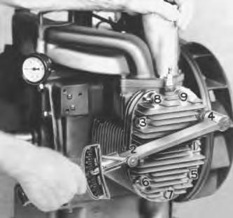
13.Cylinder Heads:
New head gaskets should be placed onto the head and held in place with the cap screws.
Be sure the washers are in place before the cap screws are positioned in the head.
Tighten the head bolts evenly and in sequence (Fig. 151) to 50 ft.–lbs. torque.
14.Governor and Magneto:
Position the gasket and governor assembly on the back plate. Fasten in place with the long bolt at the bottom. Install the lock washer and nut onthe governor side.
Attach the oil line from the top oil gallery to the governor assembly. Refer to Governor Section (Page 59) for adjustment.
Install the gasket on the magneto flange. Refer to IgnitionTiming (Page 67) for correct installation.
15.Manifolds:
Soak the manifold gaskets in water and place them into position on the engine block.
Position the manifolds onto the engine. Install two 5/16 inch cap screws in the outside bolt holes.
Place a heavy flat washer on the manifolds at the center bolt hole. Position the side baffles and install the 5/16 inch cap screws using a lockwasher and flat washer at the center hole.
Final tightening of these screws may be done after the front shroud is installed.
Make the carburetor and governor connections.
16.Spark Plugs and Cables:
Install new spark plugs in the heads. Use new gaskets. Tighten to 27 ft.–lbs. torque.
Attach the high tension cables to the magneto and spark plugs. Fasten the cable clamps in place on the intake manifold.
17.Blower Housing and Rotating Screen:
Install the blower housing and screen assembly.
18.Final adjustment:
Make final adjustments, as needed, for ignition, carburetor, governor and speed control.
TECHNICAL DATA (Kohler)
*Lubricate with grease at assembly
NOTE: Always use torque wrench on above parts.
Revision Number 600–01
4 DECEMBER 79