CHECKING THE OVERALL CONDITION OF HYDRAULIC SYSTEM NOTE: The pressure adjustments are made using the OTC Y–90 (or comparable) tester. The tester reads hydraulic flow in gallons per minute (GPM), pressure in pounds per square inch (PSI), and oil temperature in Degrees Fahrenheit. The tester can be used to check pump output, relief setting, cylinder seals and valve problems. To check the general condition of the hydraulic system, proceed as follows: 1. Connect the tester to the auxiliary tubelines at the rear of the machine. Connect a hose from the rear auxiliary tubeline to the outlet port of the tester . Connect a hose from the front tubeline to the inlet port of the tester (Fig. 6). 2. Start the engine and run it at full throttle. 3. Press down and hold the toe of the auxiliary control pedal (Fig. 6). 4. Turn the pressure control valve on the tester in (clockwise) slowly. Watch the flow reading on the tester. The flow reading should be relatively stable until the master relief valve opens. When this occurs, the flow rate will drop suddenly. A new pump will deliver about these volumes of oil until the master relief valve opens.
Dealer Copy -- Not for Resale
RECOMMENDED HYDRAULIC OIL FLOW RATE 444 (gasoline or LP gas) . . . . . . . . . . . . . . . . . . . . . . . . . 8. .GPM @ 3000 RPM 500 (gasoline or LP gas) . . . . . . . . . . . . . . . . . . . . . . . . . 8. .GPM @ 3000 RPM 500 (diesel) . . . . . . . . . . . . . . . . . . . . . . . . . . . . . . . . . . . . 8. .GPM . @ 2700 RPM 500 (electric) . . . . . . . . . . . . . . . . . . . . . . . . . . . . . . . . . .5.5 . . GPM @ 1750 RPM
An older pump will show a lower reading according to wear. 2 1
When the flow is less than 10 GPM. You can press the small low flow reading control button to get a more accurate flow reading. 5. Turning the pressure control valve knob in as far as it will go (clockwise) will give you the system pressure. It should be between 1700 and 1750 PSI.
3 4
If it is between 1650 and 1700PSI, no further check is necessary. Tilt Lines
If the pressure gauge reads less than 1650 PSI with the pressure control valve knob at its maximum clockwise position on of the following is occurring: 1. The master relief valve setting is too low or the valve is being held partially open by foreign material. 2. The hydraulic pump is worn and not capable of delivering the desired pressure. 3. The cartridge relief setting in the lift and auxiliary control valve is too low.
14 of 102
Tilt Pedal
Ref. 1 2 3 4
Description Qty. Reducer, 3/4” NPT (M) x 1/2” NPT (F) 2 Straight Adapter, 1/2” NPT (M) x 1/2” 37° Flare (M) 2 Hose, 100R1, 1/2” 37° Flare (M) x 1.2” 37° Flare (FS) 2 Carriage Screw, 5/16” x 1” (plated) 1
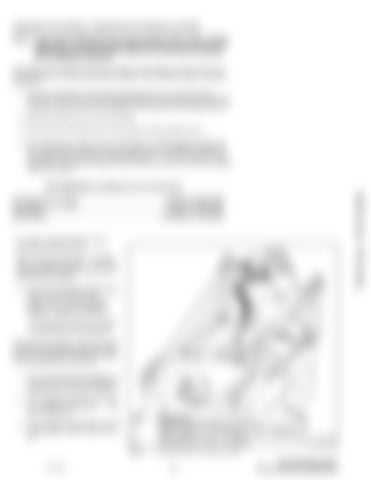
Fig. 7
Checking Condition of Hydraulic System
–4–
A–01108
444, 500, 600 Loader Service Manual Supplement
